Page is loading ...

The Whirlwind AESQbox is a multipurpose testing device for
troubleshooting AES-3 and S/PDIF digital audio signals. The
AESQbox is composed of two sections; Input and Output.
The Input section consists of the LED sample rate indicator,
the Fault LED and the decoder that converts the digital signal
into analog for the Speaker and the Line/Phones Out. The
Output section converts a choice of analog input signals into
AES-3 professional and S/PDIF digital format and delivers
them to the output connectors through Output Level and
Sample Rate controls. Clip LEDs light when output levels
reach digital zero and the Locked to Input LED indicates that
the output sample rate is matched to an input signal sample
rate.
The AESQbox has three operating modes; Cable Test, In/Out
and Pass Thru. Cable Test provides a method of testing the
integrity of digital cables, In/Out links the sample rate of the
input to the output and Pass Thru allows bridging onto a digital
signal and monitoring it both visually and aurally. Both
professional and consumer versions of AES-3 can be decoded
by the AESQbox.
Theory of Operation
The AESQbox is designed to provide a portable means of testing various aspects
of AES-3 and S/PDIF digital audio systems. It is able to generate AES-3 or S/PDIF
output signals over a sample frequency range from 32kHz to 192kHz.
Audio sources for the Output or transmitter function include a built-in microphone,
a pair of tone generators (440 Hz for the left channel, 880 Hz for the right), and an
external line-level stereo input, for an MP3 or CD player, computer sound card, etc.
An Output Level control adjusts the selected source level into the digital encoder
and Clip LEDs illuminate when the level reaches digital zero.
AES-3 or S/PDIF digital signals, both professional and consumer, can be
monitored and decoded by the Input or receiver section. The AESQbox is
capable of receiving and displaying sample frequencies from 32kHz to 192kHz,
and monitoring the audio content via the built-in speaker or line/headphone
output jack.
There are three operating modes available in the AESQbox: In/Out mode,
Pass-Thru mode, and Cable Test mode. Each of these modes is described in
detail in the following paragraphs.
When using In/Out mode, the internal digital receiver will lock to any useable
AES-3 or S/PDIF signals applied to the input connectors. The detected sample
rate will be displayed and the Lock To Input indicator will also illuminate. The
digital audio is decoded and presented to both the speaker and the Line Out
jack. At the same time, the selected test signal (mic, aux or tone) will be
converted to digital format and output from the digital output jacks. If a digital
input signal is present and locked, the digital output sample rate will mimic the
sample rate of the digital input and the output sample rate switch has no effect.
This feature allows a greater number of possible sample rates to be output
while using a single crystal-controlled frequency source. If there is no digital
input present, the output sample rate will be that selected by the sample rate
switch. In this mode, if an AES-3 or S/PDIF input signal is present but its
sample rate cannot be determined, the Fault indicator will flash on and off at a
slow rate (about once every ½ second).
Pass-Thru mode is used to monitor a digital audio signal without interrupting its
destination, essentially acting as a wiretap. The digital audio input signal is
decoded and the serial data stream is fed to the digital-to-analog converter for
analog monitoring and to the digital output encoder for re-transmission without
passing through the analog domain. To use this mode, the signal source cable
is connected to one of the digital input connectors, and the signal destination
cable is connected to one of the digital output connectors. When the input
signal is present, the appropriate sample rate indicator will illuminate as well as
the Lock indicator, and the input signal will be present on the digital output
connector. The input signal in analog format is available at the speaker and the
headphone/line output jack. Any analog input sources are ignored, as well as
the output sample rate switch.
Cable Test mode is similar to In/Out except the digital output sample rate is
independent of the digital input. The selected test signal is driven out of the
digital output at the sample rate selected by the sample rate switch. If a good
cable is connected between the input and output, the Sample Rate indicators
will display the detected sample rate, the Locked to Input LED will light and the
selected test signal will be heard over the speaker and the line output. In this
mode, the digital input will be locked and presented as audio, but if the input
and output sample rates do not match, the Fault indicator will flash on and off at
a rate of about once every ¼ second.
When testing a cable to determine if the cable has high-frequency problems,
select the highest sample rate. If the digital receiver is able to lock to the signal,
chances are that the cable is good. If the cable has integrity problems, it may not
lock at a rate of 192kHz, but may lock at a lower sample rate.
Cable test also provides an excellent means of performing an end-to-end test of
the AESQbox itself. Connecting a short cable between the input and output
allows the operator to test the functionality of all the internal components. Cable
test mode can also allow the unit to serve as an analog audio amplifier for a weak
line input signal.
The Input Sample Rate LEDs indicate the detected sample rate when they are
locked to the digital input. If the input can't lock to determine the sample rate, the
Fault LED will flash slowly. Only one LED will be illuminated at a time, except
during the Power-On Self-Test. Displayed sample rates are 32kHz, 44.1kHz,
48kHz, 88.2kHz, 96kHz, 176.4kHz, and 192kHz. The AESQbox can detect both
versions of the AES-3 bitstream; professional and consumer. If the digital input is
the professional version, the Sample Rate LEDs will glow continuously. The
consumer bitstream is identified by the Sample Rate LEDs flashing at a fast
(about once every ¼ second) rate as they indicate the detected sample rate.
The Fault LED displays three types of fault annunciations. A steadily illuminated
Fault LED indicates a malfunction in the microcontroller. Cycling the Power switch
may reset the unit. If the Fault LED flashes slowly (about once every ½ second
rate), it means the input sample rate cannot be determined (In/Out or Pass-Thru
modes), or that the digital input sample rate does not match the output sample
rate (Cable Test mode). If the Fault LED flashes quickly (about a ¼ second rate),
it means the input is locked to a signal that is not a PCM (pulse-code modulation,
or audio bit stream) signal. This signal could be a data stream or a DTS-CD
stream.
The AESQbox runs through an initialization and diagnostic sequence at power
up. During this sequence, all the indicators under digital control (the Sample
Rate, Fault and Lock LEDs) will flash on one at a time, then all will flash on and
off twice. Upon completion, the unit is ready to operate, unless the Fault LED is
steadily illuminated.
Analog monitoring of the digital input signal is done through the internal speaker
or externally by connecting an amplifier or headphones to the Line Out jack. It
provides a high-quality analog version of any AES-3 or S/PDIF signal that is
received by the AESQbox. Peak output level is +4dB, and the output is capable
of driving headphones from 32 to 100 Ohms impedance. This output is controlled
by the Line/Phones level control. The Speaker has a volume control and a three-
position switch that selects the Channel A (left) or the Channel B (right) signal
from the digital stream to be monitored. In the center position, the A and B
signals are both fed to the audio amplifier simultaneously.

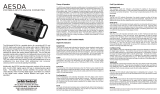
9
2
3
11
10
12
13
14
15
19
18
17
16
1
4
5
6
9. The Locked to Input LED will illuminate whenever an AES-3 or
S/PDIF digital input signal is recognized by the digital receiver. In Pass
Thru or In/Out modes, this indicates that the sample rate of the digital
output signal matches that of the input. In Cable Test mode it comes on
to indicate a good test cable; the output sample rate is dictated by the
Sample Rate switch.
10. The Output Sample Rate Switch controls, under some conditions,
the sample rate of the digital audio transmission. If there is no digital
input present, or in Cable Test mode, the output sample rate is
determined by the sample rate switch. If a digital input signal is present
and locked in Pass Thru or In/Out modes, the digital output sample
rate will mimic the sample rate of the digital input and this switch has
no effect.
11. Output Level controls the analog level presented to the A/D
Converter input. The mic, tone oscillators, and aux input are affected
by this control, typically adjusted to a level where the Clip LEDs
occasionally flash on.
12. Speaker Level adjusts the volume of the built-in speaker.
13. The Power Switch applies power from the external supply or the
batteries.
14. The Power LED is illuminated when the Power switch is ON. It will
dim as the batteries lose power, thus giving an indication of remaining
battery life.
15. Line/Phones Level controls the analog audio level present on the
Line Out 3.5mm TRS jack.
16. The Aux In Jack allows the operator to connect any analog source
to the AESQbox. The maximum input level is +4dB. This is an
unbalanced 3.5mm TRS jack with the left channel connected to the tip,
the right to the ring, and the sleeve to common.
17. The Line Out Jack provides a high-quality analog version of any
digital audio source received by the AESQbox. Peak output level is
+4dB, and the output is capable of driving headphones from 32 to 100
Ohms impedance. The left channel is connected to the tip, the right to
the ring, and the sleeve to common of the unbalanced 3.5mm TRS
jack.
18. The Battery Compartment is a slide out drawer that accepts four
“AA” alkaline cells.
19. The 6VDC external power jack is a 5.5mm x 2.1mm size with the
center contact wired positive and the barrel contact negative. A 6VDC
1000mA plug-in power supply with the correct mating connector is
supplied with the unit.
Controls and Functions
1. Input Sample Rate LEDs indicate the detected sample rate when
locked to a digital audio input. Only one will be illuminated at a time,
either full on or flashing, except during the Power-On Self-Test.
Steady state on indicates professional AES-3 data and flashing
denotes consumer AES-3 digital signal.
2. The Fault LED has three on states. Fully on means that a
microcontroller fault has been detected. Flashing slowly indicates the
unit is locked to a signal but can't determine the sample rate, or in
Cable Test mode that the input sample rate does not match the
output sample rate. Flashing rapidly means that the digital input
signal is a non-PCM format, and cannot be decoded as audio.
3. The Speaker Monitor A/B Switch controls which of the two
available audio channels is presented to the speaker for monitoring.
In the center position, the A and B signals are both on.
4. The Operating Mode Select Switch selects the desired operating mode.
5. The Analog Input Source Select Switch controls which of the three possible
analog input sources will be transmitted as digital AES-3 and S/PDIF.
6. The Clip LEDs monitor the analog input level to the A/D converters and
will start flashing dimly when the signal is about 4dB below digital full-scale,
and will illuminate steadily at about 1dB below digital full-scale.
7. The AES Digital Input XLR accepts standard AES-3 digital audio signals
over 110 Ohm balanced shielded cable, and the S/PDIF Digital Input BNC
accepts standard S/PDIF digital audio signals over 75 Ohm coaxial cable.
Input levels may be as high as 5V p-p and as low as 250mV p-p. Input
sample rates may range from 32kHz to 192kHz.The two jacks are
transformer isolated and may be used as a loop thru balun for converting
from 110 Ohm to 75 Ohm transmission lines.
8. The AES Digital Output XLR outputs standard AES-3 digital audio signals
over 110 Ohm balanced shielded cable at 5V p-p. The S/PDIF Digital Output
BNC outputs standard S/PDIF digital audio signals over 75 Ohm coaxial
cable at 5V p-p. With the unit off, the XLR and BNC can also be used as a
loop thru balun.
99 Ling Road . Rochester, NY 14612
Phone 585 663-8820 . Fax 585 865-8930
Email: [email protected]
http://www.whirlwindusa.com
7
8
/