
USER'S MANUAL
Serial
Number
Decal
Visit our website at
www.nordictrack.com
new products, prizes,
fitness tips, and much more!
V
QUESTIONS?
As a manufacturer, we are commit-
ted to providing complete customer
satisfaction. If you have questions,
or if parts are damaged or missing,
PLEASE DO NOT CONTACT THE
STORE; please contact Customer
Care.
IMPORTANT: You must note the
product model number and serial
number (see the drawing above)
before contacting us:
CALL TOLL-FREE:
1-888-825-2588
Mon.–Fri. 6 a.m.–6 p.m. MST
Sat. 8 a.m.–4 p.m. MST
ON THE WEB:
www.nordictrackservice.com
CAUTION
Read all precautions and instruc-
tions in this manual before using
this equipment. Keep this manual
for future reference.
Model No. NTEL4255.3
Serial No.
Write the serial number in the space
above for reference.

2
NordicTrack is a registered trademark of ICON IP, Inc.
TABLE OF CONTENTS
WARNING DECAL PLACEMENT . . . . . . . . . . . . . . . . . . . . . . . . . . . . . . . . . . . . . . . . . . . . . . . . . . . . . . . . . . . . . .2
IMPORTANT PRECAUTIONS . . . . . . . . . . . . . . . . . . . . . . . . . . . . . . . . . . . . . . . . . . . . . . . . . . . . . . . . . . . . . . . .3
BEFORE YOU BEGIN . . . . . . . . . . . . . . . . . . . . . . . . . . . . . . . . . . . . . . . . . . . . . . . . . . . . . . . . . . . . . . . . . . . . . .4
ASSEMBLY . . . . . . . . . . . . . . . . . . . . . . . . . . . . . . . . . . . . . . . . . . . . . . . . . . . . . . . . . . . . . . . . . . . . . . . . . . . . . . .5
HOW TO USE THE CHEST PULSE SENSOR . . . . . . . . . . . . . . . . . . . . . . . . . . . . . . . . . . . . . . . . . . . . . . . . . . .12
HOW TO USE THE ELLIPTICAL EXERCISER . . . . . . . . . . . . . . . . . . . . . . . . . . . . . . . . . . . . . . . . . . . . . . . . . .14
MAINTENANCE AND TROUBLESHOOTING . . . . . . . . . . . . . . . . . . . . . . . . . . . . . . . . . . . . . . . . . . . . . . . . . . .22
EXERCISE GUIDELINES . . . . . . . . . . . . . . . . . . . . . . . . . . . . . . . . . . . . . . . . . . . . . . . . . . . . . . . . . . . . . . . . . . .23
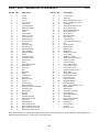
PART LIST . . . . . . . . . . . . . . . . . . . . . . . . . . . . . . . . . . . . . . . . . . . . . . . . . . . . . . . . . . . . . . . . . . . . . . . . . . . . . .24
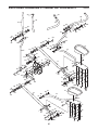
EXPLODED DRAWING . . . . . . . . . . . . . . . . . . . . . . . . . . . . . . . . . . . . . . . . . . . . . . . . . . . . . . . . . . . . . . . . . . . .25
ORDERING REPLACEMENT PARTS . . . . . . . . . . . . . . . . . . . . . . . . . . . . . . . . . . . . . . . . . . . . . . . . . .Back Cover
LIMITED WARRANTY . . . . . . . . . . . . . . . . . . . . . . . . . . . . . . . . . . . . . . . . . . . . . . . . . . . . . . . . . . . . . .Back Cover
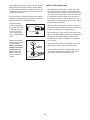
WARNING DECAL PLACEMENT
The warning decal shown here has been applied
in the location shown. If the decal is missing or
illegible, call the telephone number on the
front cover of this manual and request a free
replacement decal. Apply the decal in the loca-
tion shown. Note: The decal may not be shown
at actual size.

3
WARNING: To reduce the risk of serious injury, read all important precautions and in-
structions in this manual and all warnings on your elliptical exerciser before using your elliptical ex-
erciser. ICON assumes no responsibility for personal injury or property damage sustained by or
through the use of this product.
IMPORTANT PRECAUTIONS
1. Before beginning any exercise program,
consult your physician. This is especially im-
portant for persons over the age of 35 or per-
sons with pre-existing health problems.
2. It is the responsibility of the owner to ensure
that all users of the elliptical exerciser are
adequately informed of all precautions.
3. Your elliptical exerciser is intended for home
use only. Do not use your elliptical exerciser
in a commercial, rental, or institutional set-
ting.
4. Keep your elliptical exerciser indoors, away
from moisture and dust. Place your elliptical
exerciser on a level surface, with a mat be-
neath it to protect the floor or carpet. Make
sure that there is enough clearance around
your elliptical exerciser to mount, dismount,
and use it.
5. Inspect and properly tighten all parts regu-
larly. Replace any worn parts immediately.
6. Keep children under age 12 and pets away
from your elliptical exerciser at all times.
7. Your elliptical exerciser should not be used
by persons weighing more than 350 lbs.
(159 kg).
8. Wear appropriate exercise clothes while ex-
ercising; do not wear loose clothes that
could become caught on your elliptical exer-
ciser. Always wear athletic shoes for foot
protection while exercising.
9. Hold the handgrip pulse sensor or the handle-
bars when mounting, dismounting, or using
your elliptical exerciser.
10. Keep your back straight while using your el-
liptical exerciser; do not arch your back.
11. The pulse sensor is not a medical device.
Various factors, including the userʼs move-
ment, may affect the accuracy of heart rate
readings. The pulse sensor is intended only
as an exercise aid in determining heart rate
trends in general.
12. When you stop exercising, allow the pedals
to slowly come to a stop.
13. If you feel pain or dizziness while exercising,
stop immediately and cool down.
14. Use your elliptical exerciser only as de-
scribed in this manual.
15. The battery pack contains materials that are
considered hazardous to the environment.
Proper disposal of the battery is required by
federal law.

4
Congratulations for selecting the new NordicTrack
®
ELITE 1300 elliptical exerciser. The ELITE 1300 ellipti-
c
al exerciser is an incredibly smooth exerciser that
moves your feet in a natural elliptical path, minimizing
the impact on your knees and ankles. And the ELITE
1300 elliptical exerciser offers an array of features de-
signed to help you achieve your fitness goals in the
convenience and privacy of your home.
For your benefit, read this manual carefully before
you use the elliptical exerciser. If you have ques-
tions after reading this manual, please see the front
cover of this manual. To help us assist you, note the
p
roduct model number and serial number before con-
tacting us. The model number and the location of the
serial number decal are shown on the front cover of
this manual.
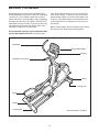
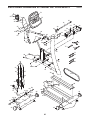
Before reading further, please familiarize yourself with
the parts that are labeled in the drawing below.
Handlebar
Console
Leveling Foot
Leveling Foot
Handgrip Pulse Sensor
Water Bottle Holder*
*No water bottle is included
Wheel
Pedal
Handle
BEFORE YOU BEGIN

5
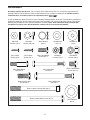
ASSEMBLY
Assembly requires two persons. Place all parts of the elliptical exerciser in a cleared area and remove the
packing materials. Do not dispose of the packing materials until assembly is completed. In addition to the in-
c
luded hex keys, assembly requires an adjustable wrench .
As you assemble the elliptical exerciser, use the drawings below to identify small parts. The number in parentheses
below each drawing is the key number of the part, from the PART LIST near the end of this manual. The number
following the parentheses is the quantity needed for assembly. Note: Some small parts may have been pre-
assembled. If a part is not in the hardware kit, check to see if it has been preassembled.
M8 Nylon
Locknut (72)–4
M4 x 19mm
Screw (57)–2
M10 Split
Washer (85)–20
M10 Washer
(67)–14
M8 Small
Washer (18)–4
M8 Washer
(69)–4
M8 x 55mm Bolt
Set (92)–2
M10 x 116mm Carriage Bolt (38)–2
M8 x 38mm Button
Bolt (58)–4
Wave Washer
(88)–4
M10 x 123mm Button Screw (87)–2
M10 Nylon
Locknut (70)–2
M4 x 16mm
Screw (47)–6
Thrust Washer
(66)–4
M10 x 13mm Button
Screw (54)–14
M10 x 65mm Bolt
Set (94)–2
M8 x 19mm Button
Screw (56)–4
M10 x 25mm Patch
Screw (48)–4

6
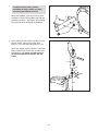
1.
A
ttach the Stabilizer (8) to the Frame (1) with
two M10 x 116mm Carriage Bolts (38) and two
M10 Nylon Locknuts (70). Tighten two Leveling
Feet (36) into the underside of the Stabilizer.
2. Have another person hold the Upright (2) in the
position shown. Connect the Upper Wire
Harness (77) to the Lower Wire Harness (78).
Attach the Upright (2) to the Frame (1) with four
M10 x 25mm Patch Screws (48) and four M10
Split Washers (85). Make sure that no wires
are pinched between the Upright and the
Frame.
1
1
2
48
85
78
2
1
70
38
8
36
77
85
48
85
To make assembly easier, read the
information on page 5 before you begin
a
ssembling the elliptical exerciser.

7
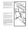
3. Attach the Track Frame (4) to the Frame (1) with
t
wo M10 x 123mm Button Screws (87) and two
M10 Split Washers (85). Finger tighten a Button
Screw into the lower hole first, and then finger
tighten a Button Screw into the upper hole.
Then, tighten both Button Screws. Note: This
step may be easier if you raise the Frame a few
i
nches in the location shown by the arrow at the
right while you attach the Track Frame.
See the inset drawing. Tighten two Leveling
Feet (36) into the underside of the Track Frame
(4).
85
4
1
87
85
87
3
4
36
4. Apply a small amount of the included grease to
the sides of two Wave Washers (88) and two
Thrust Washers (66).
Slide a Weld Spacer (89) onto the Left Crank
Arm (83). Next, identify the Left Track Arm (12),
which is marked with an “L.” Orient the Left
Track Arm as shown, and slide it onto the Left
Crank Arm. Then, slide a Wave Washer (88) on
the end of the Left Crank Arm.
Slide an M8 Small Washer (18) and an Axle Cap
(41) onto an M8 x 19mm Button Screw (56).
Next, slide a Thrust Washer (66) onto the shoul-
der of the Axle Cap. Then, tighten the Button
Screw into the end of the Left Crank Arm (83).
Make sure that the Thrust Washer remains
on the shoulder of the Axle Cap, and that the
Wave Washer (88) remains on the end of the
Left Crank Arm.
Repeat this step to attach the Right Track Arm
(11) to the right side of the elliptical exerciser.
11
4
83
89
88
41
56
12
18
66
Grease

8
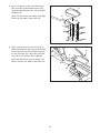
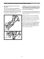
5. Attach a Pedal (21) to the Left Pedal Leg (14)
with seven M10 x 13mm Button Screws (54),
seven M10 Split Washers (85), and seven M10
W
ashers (67).
A
ttach the other Pedal (not shown) to the Right
Pedal Leg (not shown) in the same way.
5
21
67
67
85
85
54
54
14
6. Apply a thin film of grease to the barrel of an
M10 x 65mm Bolt Set (94). Next, fit the bracket
on the Left Pedal Leg (14) onto the bracket on
the Left Track Arm (12). Attach the Left Pedal
Leg to the Left Track Arm with the Bolt Set.
Attach the Right Pedal Leg (not shown) to the
Right Track Arm (not shown) in the same way.
12
94
Grease
14
94
6

9
7. Identify the Left Handlebar (19), which is marked
with an “L.” Insert the Left Handlebar into one of
the Handlebar Legs (17). Next, turn the Left
H
andlebar and the Handlebar Leg so that the
wide side of the pivot tube on the Left
H
andlebar is above the hexagonal holes in
the Handlebar Leg. Attach the Left Handlebar
with two M8 x 38mm Button Bolts (58) and two
M8 Nylon Locknuts (72). Make sure that the
Nylon Locknuts are inside of the hexagonal
holes. Do not tighten the Button Bolts yet.
Assemble the Right Handlebar (20) and the other
Handlebar Leg (17) in the same way.
7
8. Apply a small amount of grease to the sides of
two Wave Washers (88) and two Thrust Washers
(66).
Slide the Left Handlebar (19) onto the Handlebar
Axle (16) as shown. Next, slide a Wave Washer
(88) onto the end of the Handlebar Axle.
Slide an M8 Small Washer (18) and an Axle Cap
(41) onto an M8 x 19mm Button Screw (56).
Next, slide a Thrust Washer (66) onto the shoul-
der of the Axle Cap. Then, tighten the Button
Screw a few turns into the end of the Handlebar
Axle (16). Make sure that the Thrust Washer
remains on the shoulder of the Axle Cap, and
that the Wave Washer (88) remains on the
end of the Handlebar Axle.
Assemble the Right Handlebar (20) in the same
way. Then, tighten both M8 x 19mm Button
Screws (56) at the same time.
8
1
56
18
56
41
41
88
88
16
20
66
18
19
66
19
2
0
58
58
72
17
17
Hexagonal
Holes
Wide side of
pivot tube
Grease
Grease

10
9. Apply a film of grease to the barrel of an M8 x
55mm Bolt Set (92) and to a 7mm Spacer (55).
Slide an M8 Washer (69) and the Spacer onto
t
he barrel.
W
hile another person holds the front end of the
Left Pedal Leg (14) inside of the bracket on the
left Handlebar Leg (17), insert the barrel of the
Bolt Set (92) through both parts. Next, slide a
7mm Spacer (55) and an M8 Washer (69) onto
the end of the barrel of the Bolt Set. Then, turn
the screw of the Bolt Set a few turns into the
barrel. Do not overtighten the Bolt Set; the
left Handlebar Leg must be able to pivot
freely.
Attach the right Handlebar Leg (not shown) to
the Right Pedal Leg (not shown) in the same
way.
See step 7. Tighten the four M8 x 38mm Button
Bolts (58).
10. While another person holds the Display Console
(74) and the Control Console (75) near the
Upright (2), connect the Pulse Jumper Wire (76)
to the console pulse wire, and the Upper Wire
Harness (77) to the console wire harness. Insert
the excess wires into the Upright.
Set the Consoles (74, 75) on the Upright (2).
Attach the Consoles with six M4 x 16mm Screws
(47). Make sure that no wires are pinched. Do
not tighten the Screws yet.
14
9
10
2
92
17
92
55
55
69
69
47
47
77
76
75
74
Grease

11
11. Attach the Water Bottle Holder (26) to the
U
pright (2) with two M4 x 19mm Screws (57).
See step 10. Tighten the six M4 x 16mm Screws
(47).
11
2
26
57
12. Make sure that all parts of the elliptical exerciser are properly tightened. Cover the floor beneath the el-
liptical exerciser to protect the floor from damage. Note: Some extra hardware may be left over.

12
To get the best performance from the chest pulse sen-
sor, please read the instructions below.
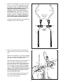
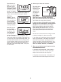
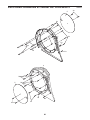
HOW TO PUT ON THE CHEST PULSE SENSOR
The chest pulse sensor consists of two components:
the chest strap and the sensor unit. Follow the steps
below to put on the chest pulse sensor.
See the inset drawing above. Insert the tab on one
end of the chest strap through the hole in one end of
the sensor unit as shown.
Wrap the chest
pulse sensor
around your
chest. Attach the
free end of the
chest strap to the
sensor unit as
described above.
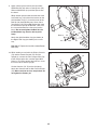
Adjust the length of the chest strap, if necessary. The
chest pulse sensor should be under your clothing,
against your skin, and as high under the pectoral mus-
cles or breasts as is comfortable. Make sure that the
logo is facing forward and is right-side-up.
Pull the sensor
unit away from
your body a few
inches and locate
the two electrode
areas on the
inner side. Using
a saline solution
such as saliva or contact lens solution, wet both elec-
trode areas. Then, return the sensor unit to a position
against your chest.
CHEST PULSE SENSOR TROUBLESHOOTING
If the chest pulse sensor does not function prop-
erly, or if the displayed heart rate is excessively
high or low, try the steps below.
• Make sure that the chest pulse sensor is worn ex-
actly as described at the left. If the chest pulse sen-
sor does not function when positioned as described,
move it slightly lower or higher on your chest.
• Each time you use the chest pulse sensor, use
saline solution such as saliva or contact lens solution
to wet the two electrode areas on the sensor unit. If
heart rate readings do not appear until you begin
perspiring, re-wet the electrode areas.
• Make sure that you are within armʼs length of the
console. For the console to display heart rate
readings, the user must be within armʼs length of
the console.
• The chest pulse sensor is designed to work with
people who have normal heart rhythms. Heart rate
reading problems may be caused by medical condi-
tions such as premature ventricular contractions
(pvcs), tachycardia bursts, and arrhythmia.
• The operation of the chest pulse sensor can be af-
fected by magnetic interference caused by high
power lines or other sources. If it is suspected that
magnetic interference may be causing a problem,
try relocating your exercise equipment.
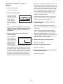
• If the chest pulse sensor still does not function prop-
erly, test the chest pulse sensor in the following way:
Hold the chest
pulse sensor
and place your
thumbs over
the electrode
areas as
shown.
Chest Strap
Sensor Unit
Tab
Buckle
Electrode Areas
Sensor
Unit
Electrode Areas
Logo
HOW TO USE THE CHEST PULSE SENSOR

13
Next, hold the chest pulse sensor near the console.
While holding one thumb stationary, begin tapping
the other thumb against the electrode area at a rate
o
f about one tap per second. Check the heart rate
reading on the console.
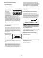
• If the chest pulse sensor does not function properly
after you have followed all of the above instructions,
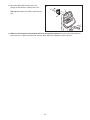
replace the battery in the following way:
Locate the battery
cover on the back of
the sensor unit. Insert
a coin into the slot in
the cover, turn the
cover counterclock-
wise, and remove the
cover.
Remove the old bat-
tery and insert a new
CR 2032 battery.
Make sure that the
battery is turned so
the writing is on
top. Reattach the
battery cover and
turn it clockwise to
close it.
CHEST PULSE SENSOR CARE
• Thoroughly dry the chest pulse sensor after each
u
se. The chest pulse sensor is activated when the
electrode areas are wetted and the chest pulse sen-
s
or is put on; the chest pulse sensor shuts off when
it is removed and the electrode areas are dried. If
the chest pulse sensor is not dried after each use, it
may remain activated longer than necessary, drain-
ing the battery prematurely.
• Store the chest pulse sensor in a warm, dry place.
Do not store the chest pulse sensor in a plastic bag
or other container that may trap moisture.
• Do not expose the chest pulse sensor to direct sun-
light for extended periods of time. Do not expose the
chest pulse sensor to temperatures above 122°
Fahrenheit (50° Celsius) or below 14° Fahrenheit
(-10° Celsius).
• Do not excessively bend or stretch the sensor unit
when using or storing the chest pulse sensor.
• Clean the sensor unit using a damp cloth—never
use alcohol, abrasives, or chemicals. The chest
strap may be hand washed and air dried.
CR 2032
Battery

14
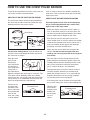
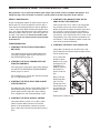
HOW TO MOVE AND LEVEL THE ELLIPTICAL
EXERCISER
Due to the size and weight of the elliptical exer-
c
iser, moving it requires two persons. With the help
of another person, lift the handle on the rear of the el-
liptical exerciser until the elliptical exerciser will roll on
the front wheels. Carefully move the elliptical exerciser
to the desired location and then lower it.
CAUTION: To decrease the risk of injury, bend your
legs and keep your back straight. Make sure to use
your legs rather than your back to lift the elliptical
exerciser. Do not attempt to move the elliptical ex-
e
rciser over an uneven surface.
If the elliptical exerciser rocks slightly on your floor, see
the inset drawings and turn the leveling feet under the
front and rear of the elliptical exerciser until the rocking
motion is eliminated.
EXERCISING ON THE ELLIPTICAL EXERCISER
To mount the elliptical exerciser, hold the handlebars
and step onto the pedal that is in the lowest position.
Next, step onto the other pedal. Push the pedals until
they begin to move with a continuous motion.
To dismount the elliptical exerciser, wait until the ped-
als come to a complete stop. The elliptical exerciser
does not have a free wheel; the pedals will con-
tinue to move until the flywheel stops. When the
pedals are stationary, step off the highest pedal first.
Then, step off the lowest pedal.
Lift
Here
Wheel
Leveling
Feet
Leveling
Foot
HOW TO USE THE ELLIPTICAL EXERCISER

15
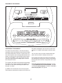
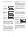
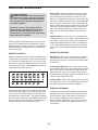
FEATURES OF THE CONSOLE
The advanced console offers a selection of features
designed to make your workouts more effective. When
the manual mode of the console is selected, the resis-
tance of the pedals can be changed with the touch of a
button. As you pedal, the console will provide continu-
ous exercise feedback. You can even measure your
heart rate using the built-in handgrip pulse sensor or
the chest pulse sensor.
The console also features personal goal programming
that allows you to choose a goal for your workout. As
you exercise, the console will display feedback until
the goal is reached.
In addition, the console offers nine preset programs.
Each program automatically changes the resistance of
the pedals and prompts you to increase or decrease
your pace as it guides you through an effective work-
out.
You can even create your own custom workout pro-
grams and save them in memory for future use.
The console also features three heart rate programs
that automatically change the resistance of the pedals
to keep your heart rate near a target heart rate as you
exercise.
To use the manual mode of the console, see page
16. To create and use a custom program, see page
18. To use a preset program, see page 19. To use a
heart rate program, see page 20.
DIAGRAM OF THE CONSOLE

16
HOW TO USE THE MANUAL MODE
1. Begin pedaling to activate the console.
The elliptical exerciser requires no batteries or
e
xternal power source. Power is supplied by a
generator while you are pedaling. To activate
the console, begin pedaling at a moderate pace.
After a few seconds, the console displays will
light. A tone will then sound and the console will
be ready for use.
2. Select the manual mode.
When the power is
turned on, the man-
ual mode will be
selected and a
track will appear in
the display. If you
have selected a
program, reselect the manual mode by pressing
the Manual button.
3. Set a workout goal if desired.
If you do not wish to set a workout goal, go to step
4.
To set a time, distance, or calorie goal for your
workout, press the increase and decrease buttons
below the Time, Distance, or Calories display. To
set a goal quickly, hold down the increase and de-
crease buttons. You can set one goal for each
workout.
For example, if you
plan to exercise for
30 minutes, press
the increase and
decrease buttons
below the Time dis-
play until the dis-
play shows a goal of “30:00.”
Note: To set a pulse goal, see HOW TO USE A
HEART RATE PROGRAM on page 20.
4. Begin pedaling and change the resistance of
the pedals as desired.
As you pedal, change the resistance of the pedals
by pressing the One-touch Resistance buttons if
desired. Note: After the One-touch Resistance
buttons are pressed, it will take a moment for the
pedals to reach the selected resistance level.
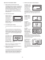
5. Monitor your progress with the displays.
The matrix—When
t
he manual mode is
selected, the matrix
w
ill show a track
representing 1/4
mile. As you exer-
cise, the indicators
around the track will light in succession until the
entire track is lit. The track will then darken and
the indicators will again begin to light in succes-
sion.
The Resistance
display—This dis-
play will show the
resistance level of
the pedals.
The Speed
display—This dis-
play will show your
pedaling speed, in
revolutions per
minute.
The Time
display—If no time
goal was set, this
display will show
the elapsed time. If
a time goal was set,
the display will
show the time remaining in your workout. Note:
When a program is selected (except for the first
heart rate program), the display will show the time
remaining in the program.
The Distance dis-
play—If no dis-
tance goal was set,
this display will
show the distance
that you have ped-
aled, in total revolu-
tions. If a distance goal was set, the display will
show the distance still to be pedaled during your
workout.

17
The Calories dis-
play—If no calorie
goal was set, this
d
isplay will show the
approximate number
o
f calories you have
burned. If a calories
goal was set, the display will show the number of
calories still to be burned during your workout.
The Pulse
display—This dis-
play will show your
heart rate when you
use the handgrip
pulse sensor or the
chest pulse sensor
(see step 6 below).
Note: You can se-
lect any of three
backlight modes for
the displays. The
“On” mode keeps
the backlight on
while the console is
on. The “Off” mode turns the backlight off. The
“Auto” mode keeps the backlight on only while you
are exercising. To change the backlight mode, first
hold down the Start button for a few seconds. The
current backlight mode will appear in the Calories
display. Next, press the One-touch Resistance 1
button to change the backlight mode. Then, press
the Start button.
6. Measure your heart rate if desired.
To use the chest
p
ulse sensor,
see page 12. To
u
se the hand-
grip pulse sen-
sor, follow the
instructions
below. Note: If
you wear the
chest pulse sensor and hold the handgrip
pulse sensor at the same time, the console will
not display your heart rate accurately.
If there are sheets of clear plastic on the metal
contacts on the handgrip pulse sensor, peel off
the plastic. Place your hands on the handgrip
pulse sensor, with your palms on the contacts.
Avoid moving your hands. When your pulse is
detected, one or two dashes will appear in the
Pulse display and then your heart rate will be
shown.
For the most accurate heart rate reading, continue
to hold the handgrips for about 30 seconds.
If your heart rate is not shown, make sure that your
hands are positioned as described. Avoid moving
your hands excessively or squeezing the metal
contacts too tightly. For optimal performance, peri-
odically clean the metal contacts using a soft cloth;
never use alcohol, abrasives, or chemicals.
7. When you are finished exercising, the console
will automatically turn off.
If the pedals are not moved for a few seconds, a
series of tones will sound, the Time display will
begin to flash, and the console will pause.
If the pedals are not moved for a few minutes, the
console will turn off and the displays will be reset.
Contacts

18
HOW TO CREATE AND USE A CUSTOM
PROGRAM
1
. Turn on the console.
S
ee step 1 on page 16.
2. Select a custom program.
To select a custom
program, press one
of the three Custom
buttons. When a
Custom button is
pressed, the indica-
tor on the button will
light.
Note: If the custom program has not yet been
defined, see step 3 to create the program. If the
program is already defined, see step 4 to use
the program.
3. Press the Start button or begin pedaling to
start the program.
Refer to the matrix.
Each custom pro-
gram is divided into
40 one-minute seg-
ments. One resis-
tance setting and
one pace setting
can be programmed for each segment. The resis-
tance setting for the first segment will be shown in
the flashing Current Segment column of the matrix.
(The pace settings are not shown in the matrix.) To
program a resistance setting and a pace setting for
the first segment, simply adjust the resistance of
the pedals as desired by pressing the One-touch
Resistance buttons and pedal at the desired pace.
When the first segment of the program ends, a se-
ries of tones will sound and the current resistance
setting and the current pace setting will be saved in
m
emory. The columns of indicators will then move
one column to the left, and the resistance setting
f
or the second segment will be shown in the flash-
ing Current Segment column. Program a resis-
tance setting and a pace setting for the second
segment as described above.
Continue programming resistance and pace set-
tings for as many segments as desired; custom
programs can have up to 40 segments.
4. Press the Start button or begin pedaling to
start the program.
The custom program will function in almost the
same way as a preset program (see steps 3 and 4
on page 19).
If desired, you can redefine the program while
using it. To change the resistance or pace set-
ting for the current segment, simply press the
One-touch Resistance buttons or change your ped-
aling pace. When the current segment ends, the
new setting will be saved in memory.
5. Monitor your progress with the displays.
See step 5 on page 16.
6. Measure your heart rate if desired.
See step 6 on page 17.
7. When you are finished exercising, the console
will automatically turn off.
See step 7 on page 17.
Current Segment

19
HOW TO USE A PRESET PROGRAM
1. Turn on the console.
See step 1 on page 16.
2. Select a preset program.
To select a preset
program, press one
of the Aerobic,
Performance, or
Endurance buttons.
When an Aerobic,
Performance, or
Endurance button is pressed, the indicator on the
button will light. When a preset program is se-
lected, a profile of the first several resistance set-
tings of the program will appear in the matrix, the
program time will appear in the Time display, the
maximum resistance setting of the program will
flash in the Resistance display, and the maximum
speed setting of the program will flash in the Speed
display for a few seconds.
3. Press the Start button or begin pedaling to
start the program.
Each program is divided into either 20 or 30 one-
minute segments. One resistance setting and one
pace setting are programmed for each segment.
Note: The same resistance setting and/or target
pace may be programmed for two or more consec-
utive segments.
When you start the
program, the resis-
tance setting for the
first segment will be
shown in the flash-
ing Current
Segment column of
the matrix. The resistance settings for the next sev-
eral segments will be shown in the columns to the
right.
When only three seconds remain in the first seg-
ment of the program, both the Current Segment
column and the column to the right will flash, a se-
ries of tones will sound, and the time will flash in
the Time display. When the first segment ends, all
resistance settings will move one column to the
left. The resistance setting for the second segment
will then be shown in the flashing Current Segment
c
olumn and the resistance of the pedals will auto-
matically change to the resistance setting for the
s
econd segment.
The program will continue until no time remains in
the Time display.
4. Use the pace guide to pace your exercise.
Throughout the program, the pace guide will
prompt you to increase or decrease your pedaling
pace. When one of the “Too Slow” indicators lights,
increase your pace; when one of the “Too Fast” in-
dicators lights, decrease your pace. When the cen-
ter indicator lights, maintain your current pace.
IMPORTANT: The pace guide is intended only
to provide a goal. Make sure to pedal at a pace
that is comfortable for you.
If you stop pedaling for several seconds, a tone will
sound and the program will pause. To restart the
program, simply resume pedaling.
5. Monitor your progress with the displays.
See step 5 on page 16.
6. Measure your heart rate if desired.
See step 6 on page 17.
7. When you are finished exercising, the console
will automatically turn off.
See step 7 on page 17.
Current Segment

20
HOW TO USE A HEART RATE PROGRAM
1. Turn on the console.
See step 1 on page 16.
2. Select a heart rate program.
To select a heart
rate program, press
one of the three
Heart Rate buttons.
When a Heart Rate
button is pressed,
the indicator on the
button will light.
If the first heart
rate program is se-
lected, a pulse sym-
bol will appear in the
matrix.
If the second or
third heart rate
program is se-
lected, a profile of
the first several tar-
get heart rate set-
tings of the program
will appear in the matrix.
3. Enter a target heart rate setting.
If the first heart rate program is selected, the
target heart rate setting for the program will flash in
the Pulse display. If desired, press the increase
and decrease buttons below the Pulse display to
change the target heart rate setting (see EXER-
CISE INTENSITY on page 23). Note: The same
target heart rate setting will be programmed for all
segments.
If the second or third heart rate program is se-
lected, the maximum target heart rate setting of
the program will flash in the Pulse display. If de-
sired, press the increase and decrease buttons
below the Pulse display to change the maximum
target heart rate setting (see EXERCISE INTEN-
SITY on page 23). Note: If the maximum target
heart rate setting is changed, the intensity level of
the entire program will change.
4. Put on the chest pulse sensor or hold the hand-
grip pulse sensor.
T
o use a heart rate program, you must wear the
chest pulse sensor or use the handgrip pulse sen-
s
or. If you use the handgrip pulse sensor, it is not
necessary to hold the handgrips continuously dur-
ing the program; however, you should hold the
handgrips frequently for the program to operate
properly. Each time you hold the handgrips,
keep your hands on the metal contacts for at
least 30 seconds. Note: When you are not holding
the handgrips, the letters “PLS” will flash in the
Pulse display instead of your heart rate.
5. Press the Start button to start the program.
The first heart rate program—This program is di-
vided into 100 one-minute segments. The same
target heart rate setting is programmed for all seg-
ments. Note: For a shorter workout, stop exercising
or select a different program before the program
ends.
The second and third heart rate programs—
These programs are divided into 30 one-minute
segments. One target heart rate setting is pro-
grammed for each segment. Note: The same tar-
get heart rate setting may be programmed for two
or more consecutive segments.
The target heart rate
setting for the first
segment will be
shown in the flash-
ing Current Segment
column of the ma-
trix. The target heart
rate settings for the next several segments will be
shown in the columns to the right.
When only three seconds remain in the first seg-
ment of the program, both the Current Segment
column and the column to the right will flash, a se-
ries of tones will sound, and all target heart rate
settings will move one column to the left. The tar-
get heart rate setting for the second segment will
then be shown in the flashing Current Segment
column.
Current Segment
Page is loading ...
Page is loading ...
Page is loading ...
Page is loading ...
Page is loading ...
Page is loading ...
Page is loading ...
Page is loading ...
-
 1
1
-
 2
2
-
 3
3
-
 4
4
-
 5
5
-
 6
6
-
 7
7
-
 8
8
-
 9
9
-
 10
10
-
 11
11
-
 12
12
-
 13
13
-
 14
14
-
 15
15
-
 16
16
-
 17
17
-
 18
18
-
 19
19
-
 20
20
-
 21
21
-
 22
22
-
 23
23
-
 24
24
-
 25
25
-
 26
26
-
 27
27
-
 28
28


NordicTrack ELITE NTEL4255.0 User manual
- Type
- User manual
- This manual is also suitable for
Ask a question and I''ll find the answer in the document
Finding information in a document is now easier with AI
Related papers
-
NordicTrack Elite 1300 Elliptical User manual
-
-
Reebok RBEL4255.1 User manual
-
-
-
-
-
-
NordicTrack NEL7095.2 User manual
-
Other documents
-
Weslo Momentum R 7.8 Elliptical User manual
-
ProForm 831.28643.0 User manual
-
-
-
ProForm 1200 E Elliptical User manual
-
HealthRider HREL32907.0 User manual
-
-
-
-
Pro-Form C895E HRE99940 User manual