Page is loading ...

IN-INST-20 LCR and SR InWall
Installation and Rough-in Bracket
Instruction Manual
IMPORTANT: There are different Installation kits for the System 20 LCR and System 20e/10e SR. Please be sure you have the
correct combination of kits and speakers before cutting any wall openings.
System 20 LCR front speakers use kit model IN-INST-
20LCR. System 20e/10e SR speakers use kit model IN-INST-20SR.
The IN-INST-20LCR is pre-installed in the optional wood InWall
enclosure IN-BOX-20LCR and this kit is not required.
These speakers can be easily mounted in most standard wall materials, from 1/2 to 1 1/2 inches (12 to 38mm) thick. The two-piece
design with a separate installation bracket makes mounting equally simple in both new and retrofit jobs. Here are some important
precautions to take before mounting:
Speaker Placement
If at all possible, please read the information about speaker locations included in the System 20 LCR and SR instructions before
deciding where to install the speakers. The following is a brief synopsis of its content.
The three front speakers should be located as close to ear height, when seated, as possible. Try to keep any difference in height
between the LR and Center speakers to 24 inches or less. Locate the LR speakers between 12 and 36 inches to each side of the
screen. Locate the Center speaker directly above or below the center of the screen.
The System 20e/10e SR surround speaker should be located directly to the side of the prime listening area, approximately 18 inches
above ear height, when seated, to no less than 24 inches down from the ceiling. There is a left and right surround speaker and
they’re marked as such on the back. They should be placed on the left or right wall relative to someone facing the screen. If they
must be located closer than 24 inches to the ceiling, turn them upside down and swap them from side to side so the direction
arrows on the back are still facing the screen.
Keep the sides of the System 20 LCR mounting hole at least 1 inch (25mm) away from beams or studs. Keep the sides of the
System 20e/10e SR at least 1/4 inch (8mm) away from beams or studs. The clamping assemblies require this much clearance and
any obstruction that’s too close will cause difficulty in mounting and may keep the speaker from sitting flush in the wall.
Wall cavity volume affects the bass performance of in-wall speakers. System 20 LCR performs optimally in a cavity volume of
1 cubic foot or larger (1728 cu. inches, measured before wall insulation is inserted). Cubic dimensions are determined by
multiplying length X width X height of the cavity. For the most consistent performance try to keep all the front speaker cavities
about the same size.
Optimum performance can be achieved using our InWall Speaker Foam Damping Kit. Follow all instructions that come with the kits for
best results. In lieu of these kits you can also fill the wall cavity with insulation, observing all the relevant instructions from the insulation
manufacturer. If you have built a back box, you can use fiberglass insulation in the enclosure. Don’t pack the cavity tightly, just fill it
loosely. There should be no insulation directly behind the speaker assembly.
Back Box Enclosure
An optional InWall back box enclosure is available for the System 20 LCR (IN-BOX-20LCR). It must be installed
before
the wall board
is applied. This enclosure provides optimum volume for the woofer and moderate isolation of sound for the adjacent room. The
enclosure comes with the Installation Bracket pre-installed.
You can also build a self-enclosed cavity within the wall that provides the required cubic volume. Please note that there is very little
room behind the speaker in a standard “2 x 4” wall cavity (1/4 inch, 6mm), so the back of any enclosure box must be made from
relatively thin materials, yet it should not physically contact the back of the speaker. Typically then, the back wall of your enclosure
should be roughly 1/8 to 1/4 inch (3 to 6mm) thick. You can also build a “fire break” type of enclosure by installing horizontal 2 x 4
or 2 x 6 cross members in the wall at appropriate positions. If you do so, be sure to caulk the edges of the studs with an all weather
silicone calking material.
Cutting the Opening
IMPORTANT: Exercise extreme care before making any holes in the wall to ensure that you won’t cut through any wires,
pipes, or other items that may be in the wall. You may sometimes, but not always, be able to determine the approximate
location of wires and pipes by looking at the locations of nearby outlets and plumbing. But their presence or absence is
never an assurance that there is not something within the wall cavity.

The System 20 LCR will not fit horizontally between studs centered on 16 inches. In such situations the studs must be notched
to allow installation, a header must be built around the speaker, or a false wall must be built.
After determining the best location for the speaker as outlined in the speaker’s Owners Manual
and above, use the enclosed template to cut the proper size hole (17 13/16 inches x
9 3/8 inches for the System 20 LCR or 11 inches x 14 3/8 inches for the System 20e/10e SR).
NOTE: It is very important to cut the opening level and square as there is no “play” between
the rear installation bracket and the speaker. If you wish, you may cut the opening slightly
oversize to allow some play for leveling.
Mounting the Installation Bracket
There must be a minimum depth behind the wall face of 3 1/2 inches
(90mm). Be sure to keep the edges of the cutout the minimum dis-
tance away from internal wall obstructions as noted above. The
speaker assembly (the part with the drivers mounted in it, the be-
zel, etc.) is designed to mount to the Installation Bracket after the
bracket is mounted into the wall board or after the wall board has been installed when using the Installation
Bracket as a rough-in kit.
Retrofit Installation
Tilt and position the bracket and fit it into the wall cutout. Angle one corner in first and then “slide” the remainder
of the assembly into the opening. Some care is required to position the bracket into the opening.
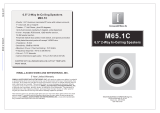
After the Installation Bracket is in the wall board, carefully insert the mount-
ing tabs into the slots located along the outside edge of the bracket as
shown in Fig. 1. They are a tight fit and are best installed by “clamping”
them using your hand as shown. The overhanging edge of the tabs should
be positioned on the outside of the wall board and are used to clamp the
frame to the wall board tightly enough to hold the assembly in place (Fig. 2). Be sure to use a level
to make sure the assembly is level in the wall. If necessary, the opening in the wall board may be
very slightly oversized to allow slight leveling adjustment. Alternately, there are predrilled holes in
the side flanges of the Installation Bracket for the System 20 LCR that may be used to hold the
assembly to the wall board with #6 self-threading screws instead of using the tabs. These screws
will be hidden by the speaker’s bezel when it is mounted. Once the bracket is in place note there
are holes near the center of the long sides that can be used to secure the input wires. There are
nylon wire ties included in the kit for this purpose. The System 20e/10e SR has its rough-
in wings molded onto the Installation Bracket. If they aren’t needed simply score the wings
along the intersection with the installation bracket (as labeled) with a sharp knife and care-
fully snap them off.
New Construction Installation
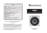
The Installation Bracket also doubles as a rough-in kit in new construction. For the System
20 LCR, simply attach the included “wings” by sliding them onto the molded keys on the
sides of the installation bracket as shown in Fig. 3. There are extra keys along the bracket
sides to allow a choice in positioning the wings. Test fit the assembly on location to deter-
mine which keys to use. The wings will allow easy mounting in walls using 16 inch or 24
inch on center construction. Once the wings are attached to the bracket simply nail or
screw the wings to the studs.
Be sure to keep the flat portions of the assembly’s mounting
flanges facing out into the room and make sure the assembly is level
.
The wallboard installer should be informed to cut out the wall board as closely as possible
to the outside edge of the bracket lip. You may leave any extra wing material to be enclosed
within the wall or cut off the excess.
Please see the speaker owners manual for the remaining instructions concerning the
actual assembly of the speaker to the bracket.
010-1025-A
Atlantic Technology 343 Vanderbilt Ave. Norwood, MA 02062 781-762-6300,
www.atlantictechnology.com
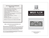
Fig. 2
The Installation Bracket
mounted in an existing
wall.
Fig. 1
Insterting the mounting tabs.Bracket
shown outside the wallboard for clarity
only.
Fig. 3
Attaching the wings to the bracket
NOTE: The center brace bar shown in the above photos of the System 20 LCR bracket
have since been eliminated.
Fig. 4 - The 20 LCR bracket above
and the 20e SR bracket below
/