Page is loading ...

User's Guide
SBOU158–August 2015
TMP107EVM User's Guide
This user’s guide describes the characteristics, operation, and use of the TMP107EVM evaluation module.
This user guide discusses how to set up and configure the software and hardware, and reviews various
aspects of the program operation. Throughout this document, the terms evaluation board, evaluation
module, and EVM are synonymous with the TMP107EVM. This document also includes an electrical
schematic, printed circuit board (PCB) layout drawings, and a parts list for the EVM.
SMAART wire is a trademark of Texas Instruments.
Windows 7 is a registered trademark of Microsoft Corporation.
All other trademarks are the property of their respective owners.
1
SBOU158–August 2015 TMP107EVM User's Guide
Submit Documentation Feedback
Copyright © 2015, Texas Instruments Incorporated

www.ti.com
Contents
1 Overview ..................................................................................................................... 3
1.1 TMP107EVM Kit Contents......................................................................................... 3
1.2 Related Documentation from Texas Instruments............................................................... 4
2 Quick-Start Setup and Use................................................................................................. 4
3 TMP107EVM Hardware..................................................................................................... 5
3.1 Theory of Operation for the TMP107EVM....................................................................... 5
3.2 TMP107EVM Motherboard Cable Adaptor...................................................................... 6
4 TMP107EVM Software...................................................................................................... 7
4.1 Hardware Requirements........................................................................................... 7
4.2 Software Installation................................................................................................ 7
4.3 Connecting the Hardware........................................................................................ 11
4.4 Launching the TMP107EVM Software ......................................................................... 13
4.5 TMP107EVM Software Operation............................................................................... 14
5 Schematic, PCB Layout, and Bill of Materials.......................................................................... 19
5.1 Schematic .......................................................................................................... 19
5.2 Assembly Drawing ................................................................................................ 20
5.3 PCB Layout ........................................................................................................ 20
5.4 Bill of Materials .................................................................................................... 21
List of Figures
1 Hardware Included with the TMP107EVM Kit............................................................................ 3
2 TMP107EVM System Setup................................................................................................ 5
3 TMP107EVM Motherboard Block Diagram............................................................................... 5
4 Three-Conductor Cable Connection....................................................................................... 6
5 TMP107EVM Software Installation Files.................................................................................. 7
6 TMP107EVM Software Installation Launch .............................................................................. 8
7 TMP107EVM Software Installation Prompts ............................................................................. 9
8 TMP107EVM Software Accept License Agreements Prompt ........................................................ 10
9 TMP107EVM Software Installation Complete .......................................................................... 11
10 Typical Response After Connecting the TMP107EVM to the Computer............................................ 11
11 Virtual Com Port in the Device Manager................................................................................ 12
12 TMP107EVM GUI Initialization Screen.................................................................................. 13
13 TMP107EVM GUI Software Default Configuration .................................................................... 13
14 Hardware Tab............................................................................................................... 14
15 Single Device Tab.......................................................................................................... 15
16 Alert Indicators on the Single Device Tab............................................................................... 16
17 Global Device Tab ......................................................................................................... 17
18 Scratchpad Memory Tab .................................................................................................. 18
19 TMP107EVM Schematic .................................................................................................. 19
20 TMP107EVM Schematic (Continued) ................................................................................... 19
21 TMP107EVM PCB Assembly Drawing .................................................................................. 20
22 PCB Top Layer ............................................................................................................. 20
23 PCB Bottom Layer ......................................................................................................... 20
24 PCB Top-Layer Silk........................................................................................................ 21
25 PCB Bottom-Layer Silk.................................................................................................... 21
List of Tables
1 TMP107EVM Kit Contents.................................................................................................. 3
2 Related Documentation..................................................................................................... 4
3 TMP107EVM Motherboard Parts List ................................................................................... 21
2
TMP107EVM User's Guide SBOU158–August 2015
Submit Documentation Feedback
Copyright © 2015, Texas Instruments Incorporated

www.ti.com
Overview
1 Overview
The TMP107 is a ±0.5°C temperature sensor with a one-wire SMAART wire™ interface, electrically-
erasable programmable memory (EEPROM), and an alert function. The TMP107 uses a one-wire
interface that works with the universal asynchronous receiver/transmitter (UART) protocol, thus making the
device ideal for many applications. The TMP107EVM is a platform for evaluating the performance of the
TMP107 under various conditions. The TMP107EVM consists of several components, the first is the
TMP107EVM motherboard that communicates with the computer, provides power, and sends and
receives appropriate digital signals. The second component is the three-conductor cable that contains
three TMP107 devices on adaptor boards (also termed coupon boards) in a daisy-chain configuration.
1.1 TMP107EVM Kit Contents
Table 1 summarizes the contents of the TMP107EVM kit. Figure 1 shows the included hardware. Contact
the Texas Instruments Product Information Center nearest you if any component is missing. It is highly
recommended that you also check the TMP107 product folder on the TI web site at www.ti.com to verify
you have the latest versions of the released software.
Table 1. TMP107EVM Kit Contents
Item Quantity
TMP107EVM motherboard 1
Three-conductor cable with three TMP107 adaptor boards 1
Figure 1. Hardware Included with the TMP107EVM Kit
3
SBOU158–August 2015 TMP107EVM User's Guide
Submit Documentation Feedback
Copyright © 2015, Texas Instruments Incorporated

Overview
www.ti.com
1.2 Related Documentation from Texas Instruments
The following document provides information regarding Texas Instruments' integrated circuits used in the
assembly of the TMP107EVM. This user's guide is available from the TI web site under literature number
SBOU158. Any letter appended to the literature number corresponds to the document revision that is
current at the time of the writing of this document. The latest revision can be found by clicking the link in
Table 2 and is also available from the TI web site, the Texas Instruments' Literature Response Center at
(800) 477-8924, and the Product Information Center at (972) 644-5580. When ordering, identify the
document by both title and literature number.
Table 2. Related Documentation
Document Literature Number
TMP107 product data sheet SBOS716
2 Quick-Start Setup and Use
Follow these steps to set up and use the TMP107EVM:
1. Download and install the Virtual Com Port drivers from www.ftdichip.com/Drivers/VCP.htm.
2. Download and install the TMP107EVM graphical user interface (GUI) software from
www.ti.com/tool/TMP107EVM.
3. If not already connected, attach the three-conductor cable to J2; see Figure 4.
4. Insert J1 into an open USB port on the computer with the software and drivers installed.
5. Select the Com Port from the Serial Port drop-down box associated with the TMP107EVM and click
the Initialize System button. When the Number of Devices field shows the appropriate number of
devices in the daisy chain (4, if the default hardware included in the TMP107EVM kit is used) and the
lower right field of the status bar reads CONNECTED in green, select the Global Device tab from the
Pages sidebar.
6. Push the Global Run Continuous button to start capturing the temperature of all TMP107 devices in
the daisy-chain and to display those measurements in the Temperature Array ºC field and in the Global
Temperature Plots waveform chart.
4
TMP107EVM User's Guide SBOU158–August 2015
Submit Documentation Feedback
Copyright © 2015, Texas Instruments Incorporated

USB Connection
to Computer
USB to UART
Converter
UART to SMAART
Converter
TMP107
Three-Conductor
Socket to Connect
Additional TMP107
Devices in a Daisy
Chain
D+
D-
TXD
RXD
I/O
I/O
5 V 3.3 V
Perforation for
Optional Break
Computer
TMP107EVM
Motherboard
TMP107
Board
3-Conductor
Cable
TMP107
Board
3-Conductor
Cable
TMP107
Board
3-Conductor
Cable
www.ti.com
TMP107EVM Hardware
3 TMP107EVM Hardware
The TMP107EVM provides basic functional evaluation of the TMP107. The fixture layout is not intended to
be a model for the target circuit and is not laid out for electromagnetic compatibility (EMC) testing.
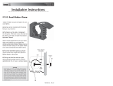
A block diagram of the TMP107EVM system setup is shown in Figure 2. The TMP107EVM PCBs have the
following features:
• The TMP107EVM motherboard has a convenient 0.6" × 3" USB stick form factor.
• The option to easily and impermanently attach a different cable to the motherboard for evaluating up to
31 devices in series in addition to the one TMP107 device on the motherboard.
• The option to snap off the section of the motherboard with the TMP107 device on it and directly solder
a cable with up to 32 devices in series to the controller section of the motherboard.
• An example layout for coupon boards that accept three-conductor cables.
Figure 2. TMP107EVM System Setup
3.1 Theory of Operation for the TMP107EVM
A block diagram of the TMP107 test board hardware is shown in Figure 3. The TMP107EVM motherboard
contains connections for the power and the bidirectional I/O line compatible with UART protocols. For
evaluation purposes, the TMP107EVM motherboard also has a break-away section of the PCB that allows
for wires (the TMP107 adaptor boards, for instance) to be soldered to the TMP107EVM motherboard
without first going through a TMP107 device.
Figure 3. TMP107EVM Motherboard Block Diagram
5
SBOU158–August 2015 TMP107EVM User's Guide
Submit Documentation Feedback
Copyright © 2015, Texas Instruments Incorporated

TMP107EVM Hardware
www.ti.com
3.2 TMP107EVM Motherboard Cable Adaptor
If not already assembled, the basic hardware setup for the TMP107EVM is to connect the three-conductor
cable to the TMP107EVM motherboard.
CAUTION
Many of the components on the TMP107EVM are susceptible to damage
caused by electrostatic discharge (ESD). Customers are advised to observe
proper ESD handling precautions when unpacking and handling the EVM,
including the use of a grounded wrist strap at an approved ESD workstation.
Connect the three bare wires on the three-conductor cable to the three-conductor, press-fit socket (J2) on
the TMP107EVM motherboard, as shown in Figure 4. Take special care to make sure that the three wires
are inserted all the way and make good electrical contact with the socket, and that the red wire goes to
V+, the green wire goes to IO2, and the black wire goes to GND. Plug the male USB-A adaptor on the
TMP107EVM motherboard into an available USB port on the computer. This cable can be removed by
inserting something rigid (like one side of a pair of tweezers) into each of the rectangular holes above
each wire to release the wire clamps inside socket J2. Releasing the clamp can also help with wire
insertion if the bare wire bends in the socket when pressure is applied.
NOTE: Always connect the three-conductor cable to the TMP107EVM motherboard before
connecting J1 to a USB port to avoid any contact issues when power is applied.
Figure 4. Three-Conductor Cable Connection
6
TMP107EVM User's Guide SBOU158–August 2015
Submit Documentation Feedback
Copyright © 2015, Texas Instruments Incorporated

www.ti.com
TMP107EVM Software
4 TMP107EVM Software
This section describes the installation and operation of the TMP107EVM software.
4.1 Hardware Requirements
The TMP107EVM software is tested on the Windows 7
®
operating system (OS) with United States
regional settings. The software should also function correctly on other Windows operating systems.
4.2 Software Installation
The computer runs the GUI software that communicates with the TMP107EVM motherboard over a USB
connection. The TMP107EVM motherboard translates the USB commands from the computer into UART
communication signals for any TMP107 devices that are attached. The TMP107EVM does not require any
additional components to operate.
4.2.1 Download and Install the FTDI Virtual Com Port Drivers
Download and install the Virtual Com Port drivers from www.ftdichip.com/Drivers/VCP.htm. The driver
version tested with this software at the time of release is 2.12.06.
If the precompiled installer for the Virtual Com Port drivers does not work properly, then it may be
necessary to use a software package to unzip the drivers from the installer executable. The hardware is in
an unrecognized category in the device manager. Choose the unidentified device and update the device
drivers using the Browse option and navigate to the folder with the driver and initialization files from the
unpacked executable.
4.2.2 Download and Install the TMP107EVM GUI Software
The TMP107EVM software is available in the TMP107EVM product folder on the TI web site
(www.ti.com). To install the software to your computer, download and unzip the installer. Launch the
TMP107EVM installation executable, setup.exe, as shown in Figure 5.
Figure 5. TMP107EVM Software Installation Files
7
SBOU158–August 2015 TMP107EVM User's Guide
Submit Documentation Feedback
Copyright © 2015, Texas Instruments Incorporated


TMP107EVM Software
www.ti.com
Read and accept the licences shown in Figure 8 to continue installing the TMP107EVM software.
Figure 8. TMP107EVM Software Accept License Agreements Prompt
10
TMP107EVM User's Guide SBOU158–August 2015
Submit Documentation Feedback
Copyright © 2015, Texas Instruments Incorporated

www.ti.com
TMP107EVM Software
When Figure 9 is displayed, the TMP107EVM GUI software is installed.
Figure 9. TMP107EVM Software Installation Complete
4.3 Connecting the Hardware
Plug J1 of the TMP107EVM motherboard into an open USB port on the computer with the drivers and
TMP107EVM GUI installed. LED D1 on the motherboard illuminates green to indicate that power is
connected to the motherboard from the USB port. Figure 10 shows the typical response when the
TMP107EVM motherboard is plugged into the USB port of the computer for the first time. Typically, the
computer responds with a Found New Hardware, USB Device pop-up dialog window. The pop-up window
then typically changes to Found New Hardware, USB Human Interface Device. This pop-up indicates that
the device is ready to be used.
Figure 10. Typical Response After Connecting the TMP107EVM to the Computer
11
SBOU158–August 2015 TMP107EVM User's Guide
Submit Documentation Feedback
Copyright © 2015, Texas Instruments Incorporated

TMP107EVM Software
www.ti.com
When the hardware is connected, verify that the device drivers are functioning correctly by checking the
Device Manager in the Ports (COM & LPT) heading, as shown in Figure 11. Find the entry labeled USB
Serial Port (COM#) and note the number assigned to the COM port. This number is used to select the
appropriate device in the software GUI; see Section 4.4.
Figure 11. Virtual Com Port in the Device Manager
12
TMP107EVM User's Guide SBOU158–August 2015
Submit Documentation Feedback
Copyright © 2015, Texas Instruments Incorporated

www.ti.com
TMP107EVM Software
4.4 Launching the TMP107EVM Software
With the TMP107EVM properly connected (see Figure 4), launch the EVM GUI software from the
Windows Start menu. This software is titled TMP107 EVM and is located in a folder called Texas
Instruments. The software launches with an initialization screen like that shown in Figure 12.
Figure 12. TMP107EVM GUI Initialization Screen
When initialized, the software shows the main TMP107EVM GUI panel in its default configuration, as
shown in Figure 13.
Figure 13. TMP107EVM GUI Software Default Configuration
13
SBOU158–August 2015 TMP107EVM User's Guide
Submit Documentation Feedback
Copyright © 2015, Texas Instruments Incorporated

TMP107EVM Software
www.ti.com
4.5 TMP107EVM Software Operation
This section primarily discusses how to operate the TMP107EVM software. Basic GUI functionality and a
description of the tabs are presented in this section.
4.5.1 TMP107EVM GUI Hardware Tab
Use the Serial Port drop-down box to select the appropriate COM port (see Figure 11). If the driver is able
to connect and successfully negotiate communication between the TMP107EVM GUI and the
TMP107EVM motherboard, then CONNECTED appears in a green box in the status bar at the bottom of
the TMP107EVM GUI. The number of devices detected in the daisy-chain is also displayed, as shown in
Figure 14. For the default configuration of the TMP107EVM, this number is four: one device is on the
motherboard and three more devices are in the cable. The communication baud rate can be adjusted on
this tab as well; choose the new desired baud rate from the drop-down box and then push the Initialize
System button to store the settings into the GUI for hardware communication.
Figure 14. Hardware Tab
NOTE: When executing commands in hardware, the Texas Instruments logo in the status bar shows
a green wave to indicate that an operation is in progress. Wait for any current operations to
complete before issuing more commands via the GUI controls.
14
TMP107EVM User's Guide SBOU158–August 2015
Submit Documentation Feedback
Copyright © 2015, Texas Instruments Incorporated

www.ti.com
TMP107EVM Software
4.5.2 TMP107EVM GUI Single Device Tab
The TMP107EVM GUI Single Device tab is shown in Figure 15. Use this tab to individually evaluate any
single device in the daisy-chain by selecting the device number (denoted by its position in the daisy-chain
with the lowest number closest to the TMP107EVM motherboard) in the Device numeric control field.
The temperature of this device can be read one time by clicking the Indiv Temp Read button. The
temperature can be read continuously at a selected interval by entering a value for the time between
readings in the Sample Rate (ms) field and then clicking the Single Run Continuous button. In either
mode, the temperature is updated in the Temperature ºC field and is graphically updated in the Single
Temperature Plot waveform chart. Most controls are disabled when Single Run Continuous is active until
Single Run Continuous is clicked again to stop capturing measurements.
Figure 15. Single Device Tab
15
SBOU158–August 2015 TMP107EVM User's Guide
Submit Documentation Feedback
Copyright © 2015, Texas Instruments Incorporated

TMP107EVM Software
www.ti.com
Use the fields labeled High Limit 1 ºC, High Limit 2 ºC, Low Limit 1 ºC, and Low Limit 2 ºC in conjunction
with the Read Alert Limits and Write Alert Limits buttons to set and validate the multiple alert limit
registers in each device of the TMP107EVM daisy-chain. Each numeric field accepts temperature values
between –128°C and +127.984375°C, and every time that a measurement is made, the green indicators
labeled Alert 1 and Alert 2 are updated based on the corresponding output bits from the selected TMP107
device. An example of how this tab looks when High Limit 1 ºC is exceeded but High Limit 2 ºC is not is
shown in Figure 16.
The High Limit 1 ºC, High Limit 2 ºC, Low Limit 1 º C, and Low Limit 2 ºC values can be stored in the
TMP107 nonvolatile memory by first unlocking the memory by clicking the NVM Locked button. Click the
Write Alert Limits button next, and finally click the NVM Unlocked button to complete the operation.
Whenever the device is reset or power-cycled, the values written are retained in the nonvolatile memory of
the TMP107 device.
Figure 16. Alert Indicators on the Single Device Tab
Use the cluster of drop-down menus titled Configuration Register in conjunction with the Read Config
Reg and Write Config Reg buttons to access the configuration register for the selected device. See the
TMP107 data sheet for more information on the definition of the bits in the configuration register.
16
TMP107EVM User's Guide SBOU158–August 2015
Submit Documentation Feedback
Copyright © 2015, Texas Instruments Incorporated

www.ti.com
TMP107EVM Software
4.5.3 TMP107EVM GUI Global Device Tab
The TMP107EVM GUI Global Device tab is shown in Figure 17. Use this tab to evaluate all the detected
devices in the daisy-chain at once.
The temperature of all devices can be read one time by clicking the Read All button. The temperature can
be read continuously at a selected interval by entering a value for the time between readings in the
Sample Rate (ms) field and then clicking the Global Run Continuous button. In either mode, the
temperature is updated in the Temperature Array ºC field and is graphically updated in the Global
Temperature Plots waveform chart, where each device is given a different line color. Most controls are
disabled when the Global Run Continuous button is active until the Global Run Continuous button is
clicked again to stop capturing measurements.
Figure 17. Global Device Tab
Use the fields labeled High Limit 1 ºC, High Limit 2 ºC, Low Limit 1 ºC, and Low Limit 2 ºC in conjunction
with the Write Alert Limits button to set the multiple alert limit registers in each device of the
TMP107EVM daisy-chain. To validate each value stored in the alert limit registers, navigate to the Single
Device tab, select each device individually, and use the Read Alert Limits button to read out the values.
Each numeric field accepts temperature values between –128°C and +127.984375°C. Because the
TMP107EVM is designed to use only three conductor cables, the two additional conductors needed to
monitor the two ALERT pins are unavailable and are therefore unsupported in this EVM. The Global Alert
Flag Clear, Global Alert 1 Pin Clear, and Global Alert 2 Pin Clear buttons are functional and clear any
latches on the ALERT pins but are also unsupported in this EVM.
The High Limit 1 ºC, High Limit 2 ºC, Low Limit 1 º C, and Low Limit 2 ºC values can be stored in the
TMP107 nonvolatile memory by first unlocking the memory by clicking the NVM Locked button. Click the
Write Alert Limits button next, and finally click the NVM Unlocked button to complete the operation.
Whenever the device is reset or power-cycled, the values written are retained in the nonvolatile memory of
the TMP107 device.
17
SBOU158–August 2015 TMP107EVM User's Guide
Submit Documentation Feedback
Copyright © 2015, Texas Instruments Incorporated

TMP107EVM Software
www.ti.com
Use the cluster of drop-down menus titled Configuration Register in conjunction with the Write Config
Reg button to write to the configuration register for all devices. See the TMP107 data sheet for more
information on the definition of the bits in the configuration register.
4.5.4 TMP107EVM GUI Scratchpad Memory Tab
The TMP107EVM GUI Scratchpad Memory tab is shown in Figure 18. Use the Device numeric field to
select the target TMP107 device for memory access. Use the Read Scratchpad button at any time to
read the contents of the memory in the target TMP107 device; the values will be populated into the gray
fields labeled x6 through xD. To write values to these registers, first fill out the white fields labeled x6
through xD with the desired target values. Click the Unlock NVM button, followed by the Write
Scracthpad button, and finally the Lock NVM button.
Figure 18. Scratchpad Memory Tab
18
TMP107EVM User's Guide SBOU158–August 2015
Submit Documentation Feedback
Copyright © 2015, Texas Instruments Incorporated

www.ti.com
Schematic, PCB Layout, and Bill of Materials
5 Schematic, PCB Layout, and Bill of Materials
The TMP107EVM motherboard and adaptor PCBs are fabricated as one PCB and broken apart. The
schematic, assembly drawing, PCB layer plots, and BOM reflect this.
5.1 Schematic
Figure 19 and Figure 20 illustrate the complete schematic of the TMP107EVM.
Figure 19. TMP107EVM Schematic
Figure 20. TMP107EVM Schematic (Continued)
19
SBOU158–August 2015 TMP107EVM User's Guide
Submit Documentation Feedback
Copyright © 2015, Texas Instruments Incorporated

Schematic, PCB Layout, and Bill of Materials
www.ti.com
5.2 Assembly Drawing
Figure 21 is the assembly drawing for the TMP107EVM.
Figure 21. TMP107EVM PCB Assembly Drawing
5.3 PCB Layout
Figure 22 and Figure 23 show the top and bottom PCB layers, respectively, of the test board.
Figure 22. PCB Top Layer
Figure 23. PCB Bottom Layer
20
TMP107EVM User's Guide SBOU158–August 2015
Submit Documentation Feedback
Copyright © 2015, Texas Instruments Incorporated
/