Page is loading ...

For customer service and support, call 1-800-846-2301
between 7am - 10pm Centeral Time Monday through Friday
If you need technical support after setting up your system,
login to the Gateway Support website at http://suport.gateway.com


1
www.gateway.com
INTRODUCTION
UNPACKING AND INSTALLATION
READ THIS BEFORE OPERATING YOUR UNIT
CAUTION: TO REDUCE THE RISK OF
ELECTRIC SHOCK, DO NOT
REMOVE COVER (OR BACK).
NO USER-SERVICEABLE PARTS
INSIDE. REFER SERVICING TO
QUALIFIED SERVICE PERSONNEL.
This symbol is intended to alert the user to
the presence of uninsulated “dangerous
voltage” within the product’s enclosure that
may be of sufficient magnitude to constitute
a risk of electric shock to persons.
This symbol is intended to alert the user
to the presence of important operating
and maintenance (servicing) instructions
in the literature accompanying the
appliance.
WARNING : TO REDUCE THE RISK OF FIRE OR ELECTRIC SHOCK,
DO NOT EXPOSE THIS APPLIANCE TO RAIN OR MOISTURE.
Note to CATV System Installer :
This reminder is provided to call the CATV system installer's attention to Article 820-40 of the NEC that provides
guidelines for proper grounding and, in particular, specifies that the cable ground shall be connected to the grounding
system of the building, as close to the point of cable entry as practical.
FCC INFORMATION
This equipment has been tested and found to comply with the limits for a Class B digital device, pursuant to Part 15 of
the FCC Rules. These limits are designed to provide reasonable protection against harmful interference in a residential
installation. This equipment generates, uses and can radiate radio frequency energy and, if not installed and used in
accordance with the instructions, may cause harmful interference to radio communications. However, there is no
guarantee that interference will not occur in a particular installation. If this equipment does cause harmful interference
to radio or television reception, which can be determined by turning the equipment off and on, the user is encouraged
to try to correct the interference by one or more of the following measures:
Reorient or relocate the receiving antenna.
Increase the separation between the equipment and receiver.
Connect the equipment into an outlet on a circuit different from that to which the receiver is connected.
Consult the dealer or an experienced radio/TV technician for help.
Units shipped to the U.S.A and Canada are designed for operation on 120V AC only.
Safety precaution with use of a polarized AC plug.
However, some products may be supplied with a nonpolarized plug.
CAUTION : To prevent electric shock, match wide blade of plug to wide slot, fully insert.
ATTENTION : Pour e’vlter choos e’lectriques, introduire la lame la plus large de la fiche dans
la borne correspondante de la prise la prise et pousser jusqu’ au fond.
U.S.A
CANADA
120V
FOR YOUR SAFETY
Avoid high temperatures. Allow for sufficient heat
dispersion when Installed on a rack.
Keep the set free from moisture, water, and dust.
Do not let foreign objects in the set.
Handle the power cord carefully. Hold the plug when
unplugging the cord.
Unplug the power cord when not using the set for long
periods of time.
Do not obstruct the ventllation holes.
Do not let insectlcides, benzene, and thinner come in
contact with the set.
Never dlsassemble or modify the set in any way.
CAUTION
Invisible laser radiation when the unit is open. Do not
stare into beam.
CAUTION : USE OF ANY CONTROLS,
ADJUSTMENTS, OR PROCEDURES OTHER THAN
THOSE SPECIFIED HEREIN MAY RESULT IN
HAZARDOUS RADIATION EXPOSURE.

SAFETY INTRODUCTION
2
www.gateway.com
1. READ INSTRUCTIONS---All the safety and operating
instructions should be read before the product is operated.
2. RETAIN INSTRUCTIONS---The safety and operating
instructions should be retained for future reference.
3. HEED WARNINGS---All warnings on the product and in the
operating instructions should be adhered to.
4. FOLLOW INSTRUCTIONS ---All operating and use instructions
should be followed.
5. CLEANING---Unplug this product from the wall outlet before
cleaning. Do not use liquid cleaners or aerosol cleaners. Use a
damp cloth for cleaning.
6. ATTACHMENTS ---Do not use attachmens not recommended
by the product manufacturer as they may cause hazards.
7. WATER AND MOISTURE---Do not use this product near water
- for example, near a bath tub, wash bowl, kitchen sink, or
laundry in a wet basement, or near a swimming pool.
8. MOUNTING---Do not place this product on an unstable cart,
stand, tripod, bracket, or table. The product may fall, causing
serious injury to a child or adult and serious damage to the
product. Use only with a cart, stand, tripod, bracket, or table
recommended by the manufacturer, or sold with the product.
Any mounting of the product should follow the manufacturer’s
instructions, and should use a mounting
accessory recommended by the
manufacturer.
9. A product and cart combination
should be moved with care. Quick
stops, excessive force, and uneven
surfaces may cause the product and
cart combination to overturn.
10. VENTILLATION---Slots and openings
in the cabinet are provided for
ventillation and to ensure reliable
operation of the product and to protect it from overheating, and
these openings must not be blocked or covered. The openings
should never be blocked by placing the product on a bed, sofa,
rug, or other similar surface. This product should not be placed
in a built-in installation such as a bookcase or rack unless
proper ventillation is provided or the manufacturer’s instructions
have been adhered to.
11. POWER SOURCES---This product should be operated only
from the type of power source indicated on the marking label. If
you are not sure of the type of power supply to your home,
consult your product dealer or local Power Company. For
products intended to operate from battery power, or other
sources, refer to the operation instructions.
12. GROUNDING or POLARIZATION---This product may be
equipped with a polarized alternating current line plug (a plug
having one blade wider than the other). This plug will fit into the
power outlet only one way. This is a safety feature. If you are
unable to insert the plug fully into the outlet, try reversing the
plug. If the plug should still fail to fit, contact your electrician to
replace your obsolete outlet. Do not defeat the safety purpose
of the polarized plug.
Alternate Warnings---This product is equipped with a three-wire
grounding-type plug, a plug having a third (grounding) pin. This
plug will only fit into a grounding-type power outlet, this is a
safety feature. If you are unable to insert the plug into the outlet,
contact your electrician to replace your obsolete outlet. Do not
defeat the safety purpose of the grounding-type plug.
13. POWER-CORD PROTECTION---Power supply cords should
be routed so that they are not likely to be walked on or pinched
by items placed on or against them, paying particular attention
to cords at plugs, convenience receptacles, and the point where
they exit from the product.
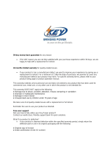
14. OUTDOOR ANTENNA GROUNDING---If an outside antenna
or cable system is connected to the product, be sure the
antenna or cable system is grounded so as to provide some
protection against voltage surges and built-up static charges.
Article 810 of the National Electrical Code, ANSI/NFPA No. 70,
provides information with regard to proper grounding of the
mast and supporting structure, grounding of the lead-in wire to
an antenna discharge unit, size of grounding conductors,
location of antenna-discharge unit, connection to grounding
electrodes, and requirements for the grounding electrode. See
Figure 1.
15. LIGHTNING---For added protection for this product during a
lightning storm, or when it is left unattended and unused for
long periods of time, unplug it from the wall outlet and
disconnect the antenna or cable system. This will prevent
damage to the product due to lightning and power-line surges.
16. POWER LINES---An outside antenna system should not be
located in the vicinity of overhead power lines or other electric
light or power circuits, or where it can fall into such power lines
or circuits. When installing an outside antenna system, extreme
care should be taken to keep from touching such power circuits
as contact with them might be fatal.
17. OVERLOADING---Do not overload wall outlets, extension cord,
or intergated convenience receptacles as this can result in a
risk of the electric shock.
18. OBJECT AND LIQUID ENTRY---Never push objects of any kind
into this product through openings as they may touch dangerous
voltage points or short-out parts that could result in a line or
electric shock. Never spill liquid of any kind on the product.
19. Servicing---Do not attempt to service this product yourself as
opening or removing covers may expose you to dangerous
voltage or other hazards. Refer all servicing to qualified service
personnel.
20. DAMAGE REQUIRING SERVICE—Unplug this product form
the wall outlet and refer servicing to qualified service personnel
under the following conditions:
a) When the power-supply cord or plug is damaged.
b) If liquid has been spilled, or objects have fallen into the product.
c) If the product has been exposed to rain or water.
d) If the product does not operate normally by following the
operating instructions. Adjust only those controls that are
covered by the operating instructions as an improper
adjustment of other controls may result in damage and will
often require extensive work by a qualified technician to
restore the product to its normal operation.
e) If the product has been dropped or damaged in any way, and
f) When the product exhibits a distinct change in performance---
this indicates a need for service.
21. REPLACEMENT PARTS---When replacement parts are
required, be sure the service technician has used replacement
parts specified by the manufacturer or have the same
characteristics as the original part. Unauthorized substitutions
may result in fire, electric shock, or other hazards.
22. SAFETY CHECK---Upon completion of any service or repairs
to this product, ask the service technician to perform safety
checks to determine that the product is in proper operating
condition.
23. WELL or CEILING MOUNTING---The product should be
mounted to a wall or ceiling only as recommended by the
manufacturer.
24. HEAT---The product should be situated away from heat
sources such as radietors, heat registers, stoves, or other
products (including amplifiers) that produce heat.
Figure 1
Example of antenna grounding as per
National Electrical Code, ANSI/NFPA 70

3
www.gateway.com
CONTENTS
1. INTRODUCTION
...............................................................................................................................................................
1
2. SAFETY INTRODUCTION
..............................................................................................................................................
2
3. PRECAUTIONS
.................................................................................................................................................................
4
4. SPEAKER SYSTEMS
......................................................................................................................................................
5
5. AVAILABLE SURROUND MODES
..............................................................................................................................
6
6. ANTENNA CONNECTION
..............................................................................................................................................
7
7. REMOTE CONTROL
........................................................................................................................................................
8
8. FRONT PANEL INFORMATION
...................................................................................................................................
9
9. REAR PANEL INFORMATION
....................................................................................................................................
10
10. REMOTE CONTROL INFORMATION
....................................................................................................................
11
11. ENTER A SETUP CODE
............................................................................................................................................
13
12. REAR PANEL CONNECTION
..................................................................................................................................
14
1) SPEAKER CONNECTION
........................................................................................................................................
14
2) TV SET, VIDEO TAPE PLAYER ETC. CONNECTION
.....................................................................................
15
13. FUNCTION AND OPERATION EXPLANATION
..................................................................................................
16
14. REGION MANAGEMENT INFORMATION
............................................................................................................
27
15. TROUBLESHOOTING GUIDE
..................................................................................................................................
28
16. SPECIFICATIONS
........................................................................................................................................................
29
17. SETUP CODE TABLE
.................................................................................................................................................
30
18. WARRANTY BOOKLET
.............................................................................................................................................
35
1) EXTENDED SERVICE PLAN
...................................................................................................................................
37
2) ACCIDENTAL DAMAGE PROTECTION PLAN
..................................................................................................
40
3) STANDARD TERMS OF SALE AND LIMITED WARRANTY AGREEMENT
.............................................
44

4
www.gateway.com
PRECAUTIONS
Taking time to read these operation instructions carefully before using the DVD Receiver will acquaint you fully with all its
features and help ensure optimum performance.
1. Power sources
This product should be operated only from the type of
power source indicated on the marking label. If you are
not sure of the type of power supply to your home,
consult your product dealer or local Power Company.
2. Overloading
Do not overload wall outlets or extension cords as this
can result in a risk of fire or electric shock. Overloaded
AC outlets, extension cords, frayed power cords,
damaged or cracked wire insulation, and broken plugs
are dangerous.
They may result in a shock or fire hazard. Periodically
examine the cord, and if its appearance indicates
damages or deteriorated receptacles, have it replaced by
our service technician.
3. Power-Cord Protection
Power supply cords should be routed so that they are not
likely to be walked on or pinched by items placed on or
against them, paying particular attention to cords at
plugs, convenience receptacles, and the point where
they exit from the product.
4. Attachments
Do not use attachments not recommended by the
product manufacturer as they may cause hazards.
5. Conditions Requiring Service
Unplug this product from the wall outlet and refer serving
to qualified service personnel under the following
conditions:
A. When the power-supply cord or plug is damaged.
B. If liquid has been spilled, or objects have fallen into the
product.
C. If the product has been exposed to rain or water.
D. If the product does not operate normally by following
the operation instructions. Adjust only those controls
covered by the operation instructions. Improper
adjustment of other controls may result in damage and
will often require extensive work by a qualified
technician to restore the product to its normal
operation.
E. If the product has been dropped or damaged in any
way, and
F. When the product exhibits a distinct change in
performance - this indicates a need for service.
6. Replacement Parts
When replacement parts are required, have the service
technician verify that the replacement parts he uses have
the same safety characteristics as the original parts. Use
of replacements specified by the product manufacturer
can prevent fire, electric shock, or hazards.
7. Power plug
• When disconnecting the power cord from the power
outlet, always take hold of the plug, and not the
wire, and pull free. Never connect or disconnect the
power plug with wet hands since you may receive
an electric shock.
• Remember to disconnect the power plug from the
power outlet when you do not intend to use the unit
for a prolonged period of time.
8. Do not remove the case and bottom panel
Any inspections or adjustments inside the unit may lead
to malfunctions and electric shocks. Do not touch any of
the inside parts.
9. Do not block the ventilation holes
Do not block the ventilation holes on the top of the unit by
placing records or other objects over them.
This will increase the inside temperature and may lead to
failure or malfunction.
10. Installation precautions
Do not install the unit in any of the following locations
since this may result in a deterioration in performance or
malfunction:
• Locations exposed to direct sunlight or near objects
radiating heat such as heating appliances.
• Locations exposed to moisture or humidity.
• Locations with poor ventilation or exposed to dust or
dirt.
• Locations which are unstable and not perfectly flat
or which are susceptible to vibration.
11. Do not wipe with thinner
Wipe the panels and case from time to time with a soft
cloth. Using any kind of thinner, alcohol, or volatile liquid
will mar the surface, cause blotching on the exterior and
erase the markings and should therefore be avoided.
Do not use insecticide sprays in the vicinity.
This unit dissipates the heat most effectively when installed on a flat surface.
Do not stand it up or install it at an angle.

5
www.gateway.com
SPEAKER SYSTEMS
POSITIONING OF THE SPEAKERS
The positioning of speakers differs according to the size and acoustics of the listening room. While actually listening to a
program source, try various speaker positions to determine which layout provides the best surround effect.
A. Front speakers
Place the font speakers in front of the listening position, to the left and right of a TV. Front speakers are
required for all surround modes.
B. Center speaker
Place a center speaker between the front speakers, on or below the TV. This speaker improves sonic
imaging and depth of field. Be sure to connect a center speaker when using the DTS/Dolby Digital and
Dolby Pro-Logic mode.
C. Rear Surround speakers
Install these speakers above and to the left and right of the level of the listener’s ears. Do not install the rear
speakers too far behind the listening position. It might be effective to direct the rear speakers towards a wall
or ceiling to further disperse the sound.
D. Subwoofer
Reproduces powerful and deep bass sounds.
Connect the speaker systems to the SPEAKERS terminals on the rear panel of the unit with the speaker cords.
To avoid damaging the speakers with a sudden high-level signal, be sure to switch the power off and check the
impedance of your speakers before connecting the speakers.
Be sure to connect the polarities of the speaker systems and the speaker terminals correctly (+ to +, - to -). If the polarities
of one of the speaker system is connected improperly, sound in the central area between the speakers will appear to the
missing, and the position of instruments will not be clear, resulting in a loss of stereo directionality.
When connecting, do not allow the conductor of the speaker cords to be exposed at the terminals and come into contact
with other terminals, as this may cause a short circuit, and damage this system.
SPEAKER LAYOUT EXAMPLE WHEN USING SURROUND MODE

6
www.gateway.com
AVAILABLE SURROUND MODES
SURROUND MODE
Select the appropriate mode according to the program
source. Note that surround speakers are needed for
DTS/DOLBY DIGITAL Dolby Pro Logic
II
Surround mode
to function. We recommend using a center speaker when
operating the unit in DTS/DOLBYDIGITAL/ Dolby Pro
Logic
II
Surround modes. The DOLBY DIGITAL button
can be pressed when you are using either Optical or
Coaxial cable as an input connection.
Manufactured under license from Dolby Laboratories.
“Dolby”, “Pro logic
II
” and the double-D symbol are
trademarks of Dolby Laboratories
DOLBY PRO LOGIC
II
and DTS buttons can be pressed
when you are operating in Analog Mode. When a Dolby
Digital format signal is input, the surround mode
automatically switches to the DOLBY DIGITAL mode.
DTS DIGITAL SURROUND MODE
DTS lets you enjoy 5.1(or 6) discrete channels of high
quality digital audio from DTS program sources bearing
the DTS trademark, such as discs, DVD and compact
discs, etc. DTS Digital Surround delivers up to 6
channels of transparent audio (which means identical to
the original masters) and results in exceptional clarity
throughout a true 360
. Sound field.
The term DTS is a trademark of DTS Technology, LLC.
Manufacrured under license from DTS Technology, LLC.
Note : DTS program sources should be played back in
the DTS mode.
DOLBY DIGITAL MODE
The Dolby Digital surround format lets you enjoy up to 5.1
channels of digital surround sound from a Dolby Digital
program source.
If you connect a DVD player or an LD player equipped
with a DOLBY DIGITAL output to the DIGITAL (Dolby
Digital)/DTS/PCM DIGITAL IN jack on a surround
receiver/amplifier and play DVD or laser discs with
trademark, you will experience even better sound quality,
greater spatial accuracy, and improve dynamic range.
This is because Dolby Digital delivers up to 5 totally
discrete, full-frequency audio channels (from left and
right, center, and surround left and right), Plus 0.1
channel called LFE (low frequency-only effects channel).
Dolby Digital is a system developed by Dolby
laboratories that transmits 5.1 channel of digital signals.
The surround system developed for movie theaters using
this system is called “Dolby SR-D (Surround Digital)”.
Because each channel is completely independent, a
realistic sound field with a “three-dimensions” feel is
achieved which gives the sound a sense of distance,
movement and relative position, creating a surprisingly
real and powerful sense of presence.
Some Dolby Digital programs information that allow you
to compress the dynamic range of a sound track, without
degrading the sound quality, for softer sound effects
when you listen late at night.
DOLBY PRO LOGIC II
Dolby Pro Logic
II
is the next generation of Dolby
Surround Pro Logic decoding technology.
Consumers enthusiastically demand 5.1-channel sound
in new programs of all kinds.
But vast numbers of programs already exist in stereo and
Dolby Surround, and many more will continue to arrive in
years to come. Pro Logic II lets consumers enjoy these
programs with a convincing 5.1-like presentation. Pro
Logic II can decode the thousands of existing Dolby
Surround movies and television shows already on the
shelf and with enhanced image stability.
The improvements in decoding techniques mean that the
discreteness of the sound field elements is better-
preserved in the decoding process than was possible
with the now universally standard Pro Logic technology,
developed in the mid-80s.

7
www.gateway.com
FM ANTENNA
FM Indoor Antenna
If you live reasonably close to a transmitter and want to
use the provided lead-type FM antenna, you will have to
connect it directly to the FM 75 Ω socket.
Fit the metal sleeve of the lead-type antenna over the
core (center) conductor of the (FM 75 Ω) socket, extend
the lead and attach it to the window frame or wall with
thumbtacks, or something similar, where reception is
best.
FM Outdoor Antenna
In an area where FM signals are weak, it will be
necessary to use a 75 Ω unbalanced-type outdoor FM
antenna using the optional matching transformer, as
shown. Generally, a 3-element antenna will be sufficient.
If you live in an area where the FM signals are
particularly weak, it may be necessary to use one with 5
or more elements. Connect the coaxial cable of the
antenna to the matching transformer as shown. After
completing connection, plug the transformer into the FM
75 Ω socket.
3. Wrap the core conductor around the central metal
fixture as shown.
AM INDOORS LOOP ANTENNA
To stand the antenna on a surface, fix the claw to the
slot.
The high performance AM loop antenna provided with
the receiver is sufficient for good reception in most areas.
Connect the loop antenna’s wires to the AM antenna
terminals as shown.
Place the antenna on a shelf or hang it on a window
frame, etc, in the direction with gives the best reception,
as far as possible from the entire system, speaker cords
and the power cords to prevent unwanted noise.
AM Loop Antenna (provided)
AM Outdoor Antenna
If the AM loop antenna provided does not deliver
sufficient reception (because you are too far from the
transmitter or in a concrete building, etc.), it may be
necessary to use an outdoor AM antenna.
Use an insulated wire more than 15 ft (5m) long, strip
one end, and connect this to the terminal as shown.
The antenna wire should be strung outdoors or indoors
near a window.
For better reception, connect the GND terminal to a
reliable ground.
Note: When connecting an outdoor AM antenna, do not
disconnect the AM loop antenna.
ANTENNA CONNECTION
1. Strip the cable and dress it as shown.
2. Press both side tabs outward to remove the cover.
AM Outdoor
Antenna
Optional

By using the provided remote control, the receiver can be
controlled from your listening position.
To use the remote control unit, point it at the REMOTE
SENSOR window on the receiver.
Notes:
• Even if the remote control is operated within the effective
range, remote control operation may be impossible if
there are any obstacles between the unit and the remote
control.
• If the remote control is operated near other appliances
which generate infrared rays, or if other remote control
devices using infrared rays are used near the DVD
Receiver, it may operate incorrectly.
• The power is turned on/off (standby) by pressing the
POWER button on the remote control. This is standby
mode.
Precautions concerning batteries.
• Be sure to insert the batteries with correct positive+
and negative– polarities.
• Use batteries of the same type. Never use different
types of batteries together.
• Rechargeable and non-rechargeable batteries can be
used. Refer to the precautions on their labels.
• When the remote control will not be used for a long
time (more than a month), remove the batteries from
the remote control to prevent them from leaking. If they
leak, wipe away the liquid inside the battery
compartment and replace the batteries with new ones.
• Do not heat or disassemble batteries and never
dispose of old batteries by throwing them in a fire.
BATTERY INSTALLATION
1. Remove the battery compartment cover.
2. Insert two “AAA” dry batteries.
Make sure that the batteries are inserted with their
positive “+” and negative “–” poles positioned
correctly.
3. Close the cover until it clicks.
If the distance required between the remote control
unit and main unit decreases, the batteries are
exhausted. In this case, replace the batteries with
new ones.
REMOTE CONTROL
8
www.gateway.com
ACCESSORIES
• RCA cord (yellow color).
• Remote control.
• Battery AAA
2 for remote control.
• T-type FM Antenna(75Ω).
• AM Loop Antenna
• Instruction Manual.

www.gateway.com
FRONT PANEL INFORMATION
9
1. POWER BUTTON
Press it to turn the power of the unit between the
standby and off modes.
Pressing the FUNCTION key(9) in the standby mode,
the unit will turn on.
2. DISIC TRAY
3. RESET
Reset the whole system (including the memory
set).
Note: Only the professional can use this RESET
function.
NOTE: Back-up Memory Function
This is the function that preserves the preset memory
and most-recent memory function. In the event of a
power failure, or if the power cord of this unit is
disconnected from the electric outlet, the back-up
memory will preserve the preset memory and most-
recent memory functions for as long as approximately 7
days.
If the power supply is interrupted for 7 days or longer, the
memory settings will be erased.
When to use RESET switch
• When this system is subjected to an electrical
shock.
• When the power is interrupted.
In this case, try the following:
Switch on the POWER, use a paper clip to press the
RESET button for more than 3 seconds duration.
If the RESET button is pressed for more than 3
seconds, all the current set up memory will be erased.
4. key
Press it to open/close the disc tray.
5. / Start/Pause playing
6. Skip to previous chapter or track.
7. Skip to next chapter or track.
8. Stop playing
9. FUNCTION key
Choose among DVD, VIDEO, FM, AM
(MW)
&AUX.
10. VFD DISPLAY UNIT
11. VOLUME / Volume up and down.
12. PHONES
Connect to headphones.
This is the jack for the headphones. Connect the plug
on the stereo headphones for private listening.
Adjust the volume so that it does not hurt your ears
when using the headphones.
If you do not intend to use your headphones, always
ensure that you unplug them.

REAR PANEL INFORMATION
10
www.gateway.com
1. POWER CORD....................... connect to the A/C socket.
2. SPEAKERS ............................ connect to the external speakers.
3. SUBWOOFER LINE OUT...... connect to the active woofer.
4. OPTICAL IN............................ connect the Audio input to the optical output of another amplifier, external recording
device or decoder.
5. COAXIAL IN / OUT................. connect the Digital audio input / output to the digital coaxial output / input of another
amplifier, external recording device or decoder.
6. DVD VIDEO OUT.................... connect to the YUV terminal on the TV set.
7. MONITOR OUT ...................... connect the video cable to the TV set.
8. S-VIDEO OUT......................... connect to the S-VIDEO socket on the TV set using the S-VIDEO cable.
9. AUDIO IN ................................ connect to the line output of a VCD or CD player.
10. AUX IN .................................. connect to the line output of an external player.
11. REC OUT.............................. connect to the line input terminals on the TAPE DECK.
12. VIDEO IN............................... connect to the video output of a VCD player.
13. ANTENNA............................. connect to AM indoor loop antenna/ lead type FM indoor antenna.

www.gateway.com
REMOTE CONTROL INFORMATION
11
1. POWER
When this key is pressed during the remote standby
state, the power of the unit can be switched on/off.
2. DEVICE
To operate the desired component with this remote
control, first select the corresponding device button.
3. ADJUST/CH. LEVEL
After pressing the CH SEL button, press these two
keys to balance the speakers.
4. AUTO
This button is used to select AUTO or MANUAL tuning
for AM and FM station. Press once to set to AUTO
again for MANUAL.
5. APS
Allocates and memorizes radio station automatically.
6. REPEAT
1) Press this key to play a single chapter/title on a
DVD video or a single track/entire disc on a CD
repeatedly.
2) When playing MP3, press this button repeatedly,
you will get the following loop; SINGLE
FOLDER
REPEAT ONE FOLDER REPEAT DISC DISC
REPEAT
DISC SCAN.
SINGLE means that only the current song will be
played, when this song finishes playing, the playback
will stop automatically.
FOLDER means that only the song in the folder you
selected will be played.
REPEAT ONE means that the song you selected will
be played repeatedly.
FOLDER REPEAT means that the folder you selected
will be played repeatedly.
DISC means the whole disc will be played.
DISC REPEAT means that the disc will be played
repeatedly.
DISC SCAN means that each track will be scanned
for 10 seconds.
7. FM MODE
Press it to alternate between stereo mode and mono
mode when listen to FM broadcast.
8. MEMO
1) When in tuner mode, press it to store the broadcast
station you wish to preset.
2) When playing CD disc, under stop mode, press this
key,
PROGRAM P00:00 appears on the TV
screen, using the number keys to preset your
desired music to be played, for instance, enter
number 2, then
PROGRAM P01:02 appears on
the TV screen, again enter number 5,
PROGRAM
P02:05
appears on the TV screen... then press
ENTER or
key to confirm, and it will start to play
according to your programming, that is music 2,
music 5...
3) When playing VCD 2.0, press PBC key to PBC
OFF first, then press PROGRAM key to carry out
the programming process.(refers to the above item
2).
4) When playing MP3, under stop mode, press this
key,
PROGRAM P00 : 0000 appears on the TV
screen. as to the programming method. please
refer to the above item 2, but after finishing
programming, you must press STOP key first, then
press ENTER or
key to confirm and play.
9. ANGLE (only for DVD)
If the DVD has multiple viewing angles, press this key
to change the angle of the screen.
a). Press this key once, you get Angle 1.
b). Press it again, you get Angle 2.
10. NTSC/PAL
Under stop mode, press this button to select TV type;
MULTI, NTSC and PAL.
11. T. SEARCH
Press this key to play your desired selection and location.
12. SUBTITLE
Press this key to select different subtitles from those
included in the DVD video disc or turn subtitles off.
13. TITLE (only for DVD)
When playing DVD including many titles, press this key
to display the title menu will appear on the television
screen, use the CURSOR to choose the title you want
to play, then press ENTER to start your chosen title.
REMOTE CONTROL RM-113

REMOTE CONTROL INFORMATION
12
www.gateway.com
14. SETUP
Press this key to access the DVD player configuration
settings by using the Setup Menu.
15. ENTER
To confirm the item, key or number that you select.
16. DISPLAY
1) DVD mode---Press this key to play the current
playing time and the remained time.
2) Press this key to display the AUDIO IN state. When
the AUDIO IN has been set to COAXIAL IN, press it
the word COAX appears on the display; When the
AUDIO IN has been set to OPTICAL IN, press it the
wod OPT appears on the display.
17. RESET +/- Press these keys to select a preset
channel when in the tuner mode.
Skip to previous chapter or track.
Skip to next chapter or track
18. TUNING +/- Tuner frequency up and down.
Fast forward (search forward)
Fast backward (search backward)
19. DIMMER
Press this key to set the brightness of the front
display. There are two settings available: normal and
dark.
20. NUMBER KEYS
These are the numeric keys for using in operating
DVD player.
21. SLEEP
No function.
22. INPUT SEL
Press this key to select FM, AM(MW), VIDEO, AUX or DVD.
23. STEP/PAUSE
When playing disc, press this key once, it will pause
the playing. press it again and the picture will move
forward frame-by-frame.
24.
Press this key to start disc playing.
25.
Press this key to stop/playing or eject the disc.
26. RETURN
Press this key to cancel the utilizing of controlled menu
picture.
27. CURSOR KEYS
28. MENU
Press this key to display the main contents of
DVD/VCD.
29. ZOOM
Enlarge the picture.
30. AUDIO
A. DVD mode---select different languages for dialogue.
B. SVCD & VCD---select one of the five audio output
modes. They are:
(1) LEFT VOCAL
(2) RIGHT VOCAL
(3) MONO LEFT
(4) MONO RIGHT
(5) STEREO
C. CD---select one of the three audio output modes;
MONO LEFT, MONO RIGHT and STEREO.
31. PROGRESSIVE SCAN
When playing DVD disc (those with DTS, no valid),
and this unit is connected to a TV set with progressive
scan function, press this key to better the picture seen
on the screen. (Note: TV TYPE automatically into
NTSC mode when this button is pressed, press it
again, the TV type into MULTI mode).
32. PBC
When playing a VCD, press this key to turn on/off
PBC.
33. 5.1/ST
When the playing is under stop situation, press it to
convert between stereo and 5.1 sound channel.
34. RANDOM
When playing MP3, press this key to select Random
or Shuffle.
When playing a CD, that is in stop mode, press this
key to select Shuffle.
35. A < > B
When playing a disc, press this key to carry out the
point-to-point repeat function, i.e. press this key once
to set to point A, and “SET A” appears on the TV
screen. After a period of time, for example, 10
minutes, press this key again, “SET B” appears on the
TV screen, then the program just finished (10 minutes)
will repeated again and again until this key be pressed
again.
36. MUTE
Press this key to mute the sound, press it again to
cancel the mute function.
37. CH SEL
Select channels by pressing this key, then use the
ADJUST/CH LEVEL key to balance speakers.
38. VOLUME /
Volume up and down.
39. DVD key
After power on this unit, you must first press this key, then
can you use this remote to operate this DVD receiver. But
not each time must you press this key first, unless other
keys, such as TV, VCR, have been pressed.

ENTERING A SETUP CODE
13
www.gateway.com
This universal remote control can operate not only this unit but also most popular brands of video components such as
TVs, VCRs, cable boxes, satellite receivers, etc.
• To operate 4 components other than this unit, you should enter the setup code for each component.
• The numbered buttons on the remote control have different function in other device modes.
• Before operating video components other than this unit with using this remote control, the setup code for each
component should be entered.
1. Turn on the component you want to control.
2. Find the setip code according to the type and the brand name of your component, referring to
Setup Code Table on
pages of 30 34.
3. Press and hold down both the ENTER button and the DEVICE button you want for more than 1 second.
4. Enter a 3 digit code, aiming the remote control at the remote sensor on the component.
Example) When entering 001
5. Enter the setup cpde for each component other than this unit you wish to control.
6. Turn on the component you want to operate.
7. Press the DEVICE button on the remote control corresponding to the component you wish to operate.
Example) When selecting
AUDIO/DVD to operate this unit.
8. Aim the remote control at the REMOTE SENSOR of the component you wish to control and press the button
corresponding to the operation you want.

www.gateway.com
REAR PANEL CONNECTION
14
SPEAKER SYSTEM CONNECTION
Be sure to connect the polarities of the speaker system and the speaker terminals correctly (+ to +, – to –).
Speaker connecting terminals:
CONNECT TO
FRONT SPEAKERS SPEAKER FRONT (L/R)
REAR SPEAKERS SPEAKER REAR (L/R)
CENTER SPEAKER SPEAKER CENTER
SUBWOOFER SPEAKER WOOFER

REAR PANEL CONNECTION
15
www.gateway.com
TV SET, VIDEO TAPE PLAYER, ETC. CONNECTION
When making the connections, refer to the connection
diagram.
Use the video cable (not provided) to connect to the TV set.
When connecting to another video tape player, use
Audio/Video cable ( not provided).
When using the S-video jack instead of the Video jack, you
should also use the S-video jack on your TV set.
S-Video signal is transmitted from an independent line of
the Video signal, not from the Video jack.
Depending on the TV system connected, you need to
make some setting to the output system of this unit. If the
TV system is NTSC or DUAL, the output system of this unit
should be set to NTSC or AUTO. If the TV system is PAL,
the output system of this unit should be set to PAL.

www.gateway.com
Turn ON/OFF the unit
1. Connect the power cord to the rated AC socket.
Press the power switch key(1/front panel). The
indication lights up. Then press the FUNCTION key
(9/front panel) or POWER key(1/remote control). The
unit has been turned on and is in DVD mode.
2. Press the POWER key(1/remote control) again to turn
off the unit and put it into the standby mode. Press the
POWER key(1/front panel) to turn off the power
completely.
Input function selection
After the unit has been turned on, press the FUNCTION
key (9/front panel) to choose your desired input signal
source. Press the FUNCTION key repeatedly, the
following loop will display on the screen:
Release the FUNCTION key at the your desired input
source, during this procedure, the volume must be
decreased.
Note: In FM, AM and AUX mode, the word “LFE” not
displayed, only the frame “
” is displayed on the
display, which means the Low Frequency signal has
output.
Basic playback
1. In DVD mode, “LOADING” will appear on the screen
and the initial picture on the TV screen. Now the unit is
searching whether there is disc inside the unit, if yes,
the menu will be shown or the disc will be played
automatically. If no, “NO DISC” will appear.
2. Press / key (4/front panel or 25/remote control)
to open the DVD disc tray, place the disc on it, press
/ key again to close the disc tray. The unit starts
to read the disc, and the DVD menu will appear on the
TV screen or the DVD will start playing automatically.
Function operation
1. / – play/pause key
A. Under the stop mode, press this key once to start
playing.
B. During the playing mode, press it once to interrupt
the playing and show the static picture.
C. Press it again to continue playing
2. / – skip backward/forward
When playing or pausing, press this key once to skip one
chapter or one music track forward or backward, then
continue playing.
3. / – fast backward/forward
(previous/next track)
A. During playing, press this key on remote control
once, the DVD disc fast forwards/backwards at 2
times the normal speed.
B. Press it again, the DVD disc fast forwards/
backwards at 4 times the normal speed.
C.Press it again, the DVD disc fast forwards/
backwards at 6 times the normal speed.
D.Press it once more, the DVD disc fast forwards/
backwards at 8 times the normal speed.
E. When playing CD, VCD disc, press this key on
remote control repeatedly, you can get 2 times, 4
times and 6 times fast forward/backwad.
F. Under the fast forward/backward mode, press /
(5 front panel) or press 15 or 24 on remote control,
it will resume normal playback.
FUNCTION AND OPERATION EXPLANATION
16

FUNCTION AND OPERATION EXPLANATION
17
www.gateway.com
4. STEP/PAUSE
A. Press this key once to activate the pause function.
Press the ENTER key or the
on remote control or
the
/
key on front panel to resume normal
playback.
B. When paused, press the PAUSE/STEP key again to
activate the STEP function, each press on this key,
makes the picture move forward one frame. If you
press the ENTER key or
on remote control or the
/ key on front panel, it will resume to normal
playback.
5. REPEAT – Repeat track or disc (for SVCD, VCD,
PBC must be in OFF mode, otherwise not valid)
A. Press this key once to repeat chapter or track.
B. Press this key again to repeat title or disc.
C. Press this key again, cancel the repetition.
6. ZOOM ---Enlarge the picture. (CD not valid)
A. Press this key (29/remote) once to enlarge 1.5 times.
B. Press it the second time to enlarge 2 times.
C. Press it the third times to enlarge 3 times.
D. Press it the fourth times to resume normal playback.
E. While playing with an enlarged picture, press the
cursor
key on remote control to move the
picture.
7. MENU – (CD is not valid)
A. Press the MENU key (28/remote control) to show the
main contents of the DVD.
B. Use the cursor
key on remote control to
choose the content or music you want.
C. Press / on front panel or the ENTER or key
on remote control to confirm playing.
In addition, if there are subtitles, use the above steps
a-b to choose the your desired subtitles.
If the disc being played without contents, this key will
be no function.
When playing VCD, SVCD, this key is used as the
PBC switch.
8. DISPLAY – Press this key, to check the current
playing time and the remaining time of the
title/chapter/track being played and the total
remaining time of the disc being played.
A. Press the DISPLAY key (16/remote control) to
display the title, chapters included in this disc and the
playing time.
B. Press it again to display the
remaining
time of the
title.
C. Press it again to display the playing time of the
chapter.
D. Press it again to display the remaining time of this
chapter.
Press it again to clear up the time display mode on
the TV screen.
9. TITLE – (CD, VCD, SVCD not valid)
A. Press the TITLE key (13/remote control) to show the
main contents of the disc.
B. Use the cursor
keys on front panel or
remote control to select your desired content or
number.
C. Press / or ENTER on the front panel or
key
on the remote control to resume playing.
Note : The TITLE key does not work with discs that
have not contents.
TITLE
1
CHAPT
2
MIN
08
SEC
18
TITLE
1
CHAPT
2
MIN
1.36.
SEC
23

www.gateway.com
FUNCTION AND OPERATION EXPLANATION
18
10. ANGLE – to choose the angle of the picture
(CD, VCD, SVCD not valid).
Press this key repeatedly to choose the angle of the
scenes. (Does not work with DVDs recorded without
multi-angular, not valid).
With the DVD set on the multi-angular mode ON, when
playing DVD recorded with multi-angular, the current
playing angle mark appears on the upper right angle on
the TV screen.
11. SUBTITLE – to choose the different subtitles
Press this key(12 remote control) repeatedly to select
your desired subtitles(Does not work with DVDs recorded
without subtitles, not valid).
12. AUDIO
A. When playing a DVD disc
a. Press this key (30/remote control) to select audio
channel output.
b. Press this key again to select audio channel 2
output.
B. When playing a VCD or SVCD
Press this key (30/remote control)repeatedly to select
one of the following five audio output modes:
LEFT VOCAL, RIGHT VOCAL, MONO LEFT,
MONO RIGHT, STEREO.
C. CD --- select one of the three audio output modes:
MONO LEFT, MONO RIGHT and STREO.
Audio channel 1, 2...... is the music style recorded on
the disc. If the disc does not the characteristic, “NOT
VALID” will appear.
13. RETURN – (CD is not valid)
A. During playing a VCD or SVCD, press the
“RETURN” key to go back to the main menu.
B. During playing, after pressing “SETUP” to enter the
setup function, press the RETURN key to exit SETUP
and start playing again.
14. T.SEARCH --- location selection key
When playing DVD
A. Press T.SEARCH key (11/remote control),
“TITLE---CHAPTER---” will be displayed.
As shown on the above figure, TITLE 01/01 means
there is one title. Chapter 001/025 means there are
25 chapters (from 001 to 025).
B. Use the direction key
or to confirm the chosen
title or chapter. Use the numeric keys to enter the
number of the chosen title and chapter.
As shown on the above figure, use
to move
cursor to TITLE, then enter a title number.
As shown on the following figure, use to move
the cursor to chapter 001, then enter number 008.
C. Press the ENTER key to confirm. The disc will start
playing from this title and chapter.
D. Press the T.SEARCH key two times to display
time--:--:--: h:m:s.
/