Page is loading ...

Innovation in soft start technology
synergy
tm
USER MANUAL
MAN-SGY-017. Version 01

Synergy Series Soft Start User Manual
MAN-SGY-017. Version 01. 25/07/2016
2
synergy
tm
user guide
Fairford Electronics Ltd
Bristow House
Gillard Way, Ivybridge
PL21 9GG
UK
www.fairford.com

Synergy Series Soft Start User Manual
MAN-SGY-017. Version 01. 25/07/2016
3
Contents
Redefining Motor Control ............................................................................................................................................ 9
Safety ............................................................................................................................................................................ 10
Safety (continued) ....................................................................................................................................................... 11
User Manual Revision Guide ..................................................................................................................................... 12
1. Mechanical Installation .......................................................................................................................................... 13
1.1 Mounting ........................................................................................................................................................... 13
1.2 Requirements for an Enclosure ...................................................................................................................... 13
1.3 Enclosure Ventilation ....................................................................................................................................... 13
1.4 Altitude .............................................................................................................................................................. 14
1.5 Derate ................................................................................................................................................................ 14
1.6 Dimensions ....................................................................................................................................................... 15
1.7 Mechanical Specification ................................................................................................................................ 19
2. Electrical Installation............................................................................................................................................... 21
2.1 Warnings .......................................................................................................................................................... 21
2.1.1 Isolation ..................................................................................................................................................... 21
2.1.2 Electrical Control Supply Requirements ................................................................................................ 21
2.1.3 Access ........................................................................................................................................................ 21
2.1.4 Fuse Protection ......................................................................................................................................... 21
2.1.5 Safety ......................................................................................................................................................... 21
2.2 Electrical Connections ..................................................................................................................................... 22
2.2.1 Electrical Supplies ..................................................................................................................................... 22
2.3 Technical Information and Standards ........................................................................................................... 22
2.4 Electrical Specifications ................................................................................................................................... 23
2.4.1 Rating Tables ............................................................................................................................................. 23
2.5 Short Circuit Protection ................................................................................................................................... 24
2.6 Motor Overload Protection ............................................................................................................................. 25
2.7 Wire Sizes and Torques ................................................................................................................................... 26
2.8 Electrical Connections ..................................................................................................................................... 28
2.9 Electrical Wiring ................................................................................................................................................ 29
2.9.1 Three Wire Control ................................................................................................................................... 30
2.9.2 User Programmable Control ................................................................................................................... 30
2.9.3 Reversing Configuration .......................................................................................................................... 31
2.9.3 Sequential Soft Start Configuration ....................................................................................................... 32
3. Configuration and Parameters.............................................................................................................................. 34
3.1 Status LED ......................................................................................................................................................... 34
3.2 Configuration Overview .................................................................................................................................. 34

Synergy Series Soft Start User Manual
MAN-SGY-017. Version 01. 25/07/2016
4
3.2.1 Auto Setup Procedure ............................................................................................................................. 34
3.2.2 Setup by Individual Parameter Settings ................................................................................................ 34
3.3 Configuration From Touchscreen .................................................................................................................. 34
3.3.1 Auto Setup ................................................................................................................................................. 34
3.3.2 Individual Parameter Setup .................................................................................................................... 34
3.4 On Screen Menus ............................................................................................................................................. 35
3.5 Auto-Setup Example ........................................................................................................................................ 36
3.6 Auto-Setup Parameter Settings ...................................................................................................................... 37
3.7 Parameter Summary ....................................................................................................................................... 39
3.7.1 Summary – Parameters for Touchscreen Setup – “Advanced” Category .......................................... 39
3.7.2 Summary – Parameters for Touchscreen Setup – “I/O” Category ...................................................... 42
3.7.3 Summary – Parameters for Touchscreen Setup – “Monitor” Category.............................................. 43
3.7.4 Summary – Parameters for Touchscreen Setup – “Log” Category ..................................................... 44
3.7.5 Summary – Parameters for Touchscreen Setup – “Device” Category ....................................................... 46
3.8 Auto-Setup Menu ............................................................................................................................................. 47
3.9 Advanced Menu ............................................................................................................................................... 49
3.10 Input / Output ................................................................................................................................................ 68
3.11 Monitor ........................................................................................................................................................... 74
3.12 Log ................................................................................................................................................................... 79
3.13 Device ............................................................................................................................................................ 101
3.14 Functional Summaries ................................................................................................................................. 107
3.15 Saving and Loading an synergy
TM
Configuration File
..................................................................... 111
3.16 Saving a Log file
.......................................................................................................................................... 111
4. Communication..................................................................................................................................................... 113
4.1 Modbus RTU Serial Communications .......................................................................................................... 113
4.1.1 Modbus RTU Communications Interface ............................................................................................ 113
4.1.2 Modbus RTU Connections ..................................................................................................................... 113
4.1.3 Modbus Communications Configuration
....................................................................................... 114
4.1.3Transmission Modes
............................................................................................................................. 114
4.1.4 Message Structure For RTU Mode
................................................................................................. 115
4.1.5 Address
................................................................................................................................................. 115
4.1.6 Function Code
..................................................................................................................................... 115
4.1.7 Data Field
............................................................................................................................................... 115
4.1.8 CRC ........................................................................................................................................................... 115
4.1.9 Supported Functions
......................................................................................................................... 115
4.1.10 Memory Map ........................................................................................................................................ 117
4.1.11 Message Timing .................................................................................................................................... 118

Synergy Series Soft Start User Manual
MAN-SGY-017. Version 01. 25/07/2016
5
4.2 Modbus TCP .................................................................................................................................................... 119
4.2.1 synergy
TM
Configuration ........................................................................................................................ 119
4.2.2 IP Address Configuration ....................................................................................................................... 119
4.2.3 Modbus TCP Module Front Panel Indicators. ..................................................................................... 121
4.2.4 Modbus TCP Functionality ..................................................................................................................... 122
4.3 Ethernet /IP ..................................................................................................................................................... 123
4.3.1 Synergy Configuration ........................................................................................................................... 123
4.3.2 IP Configuration ...................................................................................................................................... 123
4.3.3 Ethernet /IP Module Front Panel Indicators. ....................................................................................... 123
4.3.4 Ethernet /IP Functionality ...................................................................................................................... 123
4.3.5 Ethernet /IP Control ............................................................................................................................... 123
4.4 Profibus DP ..................................................................................................................................................... 125
4.4.1 Synergy Configuration ........................................................................................................................... 125
4.4.2 Profibus DP Module Front Panel Indicators ........................................................................................ 125
4.4.3 Profibus DP Module Pinout ................................................................................................................... 126
4.4.4 Profibus DP Control ............................................................................................................................... 126
4.5 Anybus Module Installation .......................................................................................................................... 128
5. Modbus RTU Parameter Table ............................................................................................................................ 130
6.Trip and Fault Codes.............................................................................................................................................. 169
6.1Trip Code Descriptions ................................................................................................................................... 169
6.2 Fail Safe Codes ............................................................................................................................................... 172
6.2.1 Main Board Trip (2402 – 2436)
........................................................................................................... 172
6.2.2
Touchscreen Trip (2501 – 2581)
........................................................................................................ 172
6.2.3 Logging Trip (2601 – 2603)
.................................................................................................................. 173
7. Intelligent Energy Recovery (iERS) ....................................................................................................................... 174
7.1 Principles ......................................................................................................................................................... 174
7.2 Advantages of IERS ........................................................................................................................................ 175
7.3 Additional Benefits in Practice ...................................................................................................................... 176
7.4 How Much Energy? ........................................................................................................................................ 176
7.5 Estimating Energy Savings ............................................................................................................................ 177
7.5.1 Basis for estimation ............................................................................................................................... 177
7.6 Examples of Estimated Saving ...................................................................................................................... 178
7.7 iERS with Synergy
......................................................................................................................................... 178
8. Applications ........................................................................................................................................................... 180
8.1 Motor Suitability and Associated Considerations ...................................................................................... 180
8.1.1 Suitability ................................................................................................................................................. 180
8.1.2 Induction Motor Characteristics ........................................................................................................... 180

Synergy Series Soft Start User Manual
MAN-SGY-017. Version 01. 25/07/2016
6
8.1.4 Rating ....................................................................................................................................................... 180
8.1.5 Maximum Motor Cable Length ............................................................................................................. 181
8.1.6 Power Factor Correction Capacitors .................................................................................................... 181
8.1.7 Lightly Loaded, Small Motors ................................................................................................................ 181
8.1.8 Motors Fitted with Integral Brakes ....................................................................................................... 181
8.1.9 Older Motors ........................................................................................................................................... 181
8.1.10 Wound-rotor or Slip-ring Motors ....................................................................................................... 181
8.1.11 Enclosures ............................................................................................................................................. 181
8.1.12 High-Efficiency Motors ......................................................................................................................... 181
8.1.13 EU Compliance with the EMC Directive ............................................................................................. 181
8.1.14 Fuses ...................................................................................................................................................... 182
8.2 Rules for Specific Applications ..................................................................................................................... 182
8.2.1 In-Delta Operation ................................................................................................................................. 182
8.2.2 High Inertia Loads .................................................................................................................................. 182
8.2.3 Frequent Starting ................................................................................................................................... 182
8.2.4 iERS ........................................................................................................................................................... 182
8.2.5 Soft-Stopping .......................................................................................................................................... 182
8.2.6 Reversing Drives and Plug-braking ...................................................................................................... 183
8.2.7 Replacement of Fluid Couplings ........................................................................................................... 183
8.2.8 Two-speed Motor Applications ............................................................................................................. 183
8.2.9 Multiple Motor Starting ......................................................................................................................... 183
8.2.10 Overhauling Loads ............................................................................................................................... 183
8.2.11 Application Table .................................................................................................................................. 184
8.3 Concepts and principles of fixed-speed induction motor starting and control. .................................... 185
8.3.1 Introduction ............................................................................................................................................ 185
8.3.2 The Induction Motor .............................................................................................................................. 185
8.3.3 Starting Induction Motors ..................................................................................................................... 188
8.3.4 Electro-Mechanical Methods Of Starting ............................................................................................. 188
8.3.5 The Semiconductor Motor Controller .................................................................................................. 190
8.3.6 Running Induction Motors .................................................................................................................... 190
8.3.7 Reliability Considerations ...................................................................................................................... 192
9. EMC ......................................................................................................................................................................... 193
9 Electromagnetic Compatibility (EMC)
........................................................................................................... 193
9.1 Introduction
................................................................................................................................................. 193
9.2 Applicable Standard Within the EU
.......................................................................................................... 193
9.3 Mandatory Requirements Within the EU
................................................................................................. 193
9.4 Guidance for Installation Personnel and System Designers
.............................................................. 193

Synergy Series Soft Start User Manual
MAN-SGY-017. Version 01. 25/07/2016
7
9.5 EMC Basic Criteria
....................................................................................................................................... 194
9.6 Purchasing Implications of Meeting an EMC Standard
....................................................................... 194
9.7 Basic EMC Considerations
......................................................................................................................... 194
9.7.1 Immunity ................................................................................................................................................. 194
9.7.2 Emissions
............................................................................................................................................... 194
9.7.3 Emissions - Harmonics
....................................................................................................................... 194
9.7.4 Emissions - Radio Frequency (RF)
...................................................................................................... 195
9.7.5 Emissions - Conducted
........................................................................................................................ 195
9.7.6 Important Systems Information
...................................................................................................... 195
9.7.7 Strategies for Attaining and Maintaining EMC Compliance
......................................................... 196
A1. Soft Starter Sizing ............................................................................................................................................... 198
A.1.1 Introduction ................................................................................................................................................. 198
A1.2 Index Rating .................................................................................................................................................. 199
A1.3 Standard Overload Current Profile and Duty Cycle
....................................................................... 199
A1.4 Sizing Chart ................................................................................................................................................... 201
A2. Glossary of Terms............................................................................................................................................... 203
A3. Starter View ......................................................................................................................................................... 205
A3.1 Introduction .................................................................................................................................................. 205
A3.2 Installation .................................................................................................................................................... 205
A3.3 User Interface ............................................................................................................................................... 206
A3.4 Parameter Viewer and Editor ..................................................................................................................... 207
A3.4.1 Opening Parameter Files .................................................................................................................... 207
A3.4.2 Parameter View Layout ....................................................................................................................... 208
A3.4.3 Working with the Parameter View. .................................................................................................... 209
A3.5 Log File Viewer ............................................................................................................................................. 213
A3.6 Firmware Upgrade Utility (Release Builder) ............................................................................................. 216
A4. Updating synergy
TM
Firmware .......................................................................................................................... 219
A4.1 Introduction .................................................................................................................................................. 219
A.4.2 Instruction for Updating ............................................................................................................................ 219
A5. User Serviceable Items ...................................................................................................................................... 222
A5.1 Fan Replacement ......................................................................................................................................... 222
A5.1.1 Replacement Fan Part Numbers ............................................................................................................ 222
A5.1.2 Fan Replacement Procedure – SGY-101 thru SGY-305......................................................................... 222
A5.1.3 Fan Replacement Procedure – SGY-307 and SGY-309 ......................................................................... 224
A5.1.3 LCD Touchscreen Replacement .............................................................................................................. 225
A6. Remote Keypod Setup – SGY-010 ..................................................................................................................... 227
A6.1 Introduction .................................................................................................................................................. 227

Synergy Series Soft Start User Manual
MAN-SGY-017. Version 01. 25/07/2016
8
A6.2 Network Connection ................................................................................................................................... 227
A6.3 Remote Keypod Operation ......................................................................................................................... 229

Synergy Series Soft Start User Manual
MAN-SGY-017. Version 01. 25/07/2016
9
The original pioneers of soft start technology, Fairford Electronics Limited have been at the forefront of
motor control innovation since the 1970’s. Fairford have manufactured and supplied over 1 million
products into the market place and are recognised as the reference point for many control solution
providers worldwide.
In 2009, the need for a new technology that bridged the gap between drive technology and soft start was
recognised and the development process began for synergy™, a new form of motor control that met the
needs of those requiring the functionality of a drive in a fixed speed application. The key aspects of a drive
(energy saving and communications) as well as original features of a soft start including internal bypass and
lower cost, meant the base design was enhanced even further.
iERS (intelligent Energy Recovery System) is Fairford’s patented energy saving system with a combined
internal bypass to save energy on lightly loaded motors. iERS reduces the voltage and current supplied to
lightly loaded motors to only allow the motor to consume the exact amount of energy required to maintain
the speed at that load.
When the motor is at full load the internal bypass closes, this reduces the losses produced by the control
element. This combined approach enables iERS to save more energy in more applications than any other
competing technology.
iERS has been market proven over the past 10 years and has now reached its latest development realising
even greater savings. Applications such as compressors, refrigerators, pump jacks, moulding machines and
chillers can typically see savings of around 8-40% of total energy consumption when lightly loaded.
With size and cabinet capacity an ever increasing focus, Fairford developed the world’s smallest power to
size ratio motor controller. Synergy™ utilised Fairford’s globally renowned Automatic Setup feature to
program the unit to each individual application using only a 8 button process. Since then it has removed
buttons and uses touch screen technology bringing the user interface to even greater management levels.
With full motor overload protection as well as full data logging, upgradeable software in the field and
extensive input/output programmability, synergy™ meets all of the key design
Redefining Motor Control

Synergy Series Soft Start User Manual
MAN-SGY-017. Version 01. 25/07/2016
10
Important information
Installers should read and understand the instructions in this guide prior to installing, operating and
maintaining the soft start. The following symbols may appear in this guide or on the soft start to warn of
potential hazards or to draw attention to certain information.
Dangerous Voltage
Indicates the presence of a hazardous voltage which could result in personal injury or death.
Tension dangereuse
Indique la présence d’une tension dangereuse qui peut entaîner des blessures ou la mort.
Warning/Caution
Indicates a potential hazard. Any instructions that follow this symbol should be obeyed to avoid possible
damage to the equipment, and personal injury or death.
Avertissement/Mise en garde
Indique un danger potentiel. Toutes les instructions suivant ce symbole doivent être observées, afin d’éviter les
dommages de l’équipement et les blessures ou la mort.
Protective Earth (Ground)
Indicates a terminal which is intended for connection to an external conductor for protection against
electric shock in case of a fault.
Mise à la terre (Masse)
Indique une borne dont l’usage prévu est d’être connecter à conducteur externe pour assurer la protection contre
les chocs électriques en cas de défauts.
Caution Statements
The examples and diagrams in this manual are included solely for illustrative purposes. The information
contained in this manual is subject to change at any time and without prior notice. In no event will
responsibility or liability be accepted for direct, indirect or consequential damages resulting from the use or
application of this equipment.
Mises en garde
Les exemples et les schémas de ce manuel ne sont donnés qu’à titre illustratif. Les informations présentées dans
ce manuel peuvent être modifiées sans avis préalable. En aucun cas nous n’assumons la responsabilité ou
l’obligation pour les dommages directs, indirects ou consécutifs qui résultent de l’utilisation ou application de cet
équipement.
Short Circuit
Fairford soft starts are not short circuit proof. After severe overload or short circuit, the operation of the
soft start should be fully tested by an authorised service agent.
Court-circuit
Les démarreurs progressifs Fairford ne sont pas à l’épreuve des courts-circuits. Après une forte surcharge ou un
court-circuit, le fonctionnement du démarreur progressif doit être intégralement vérifié par un agent de
maintenance agréé.
Safety

Synergy Series Soft Start User Manual
MAN-SGY-017. Version 01. 25/07/2016
11
• Synergy™ soft starts contain dangerous voltages
when connected to the mains supply. Only
qualified personnel that have been completely
trained and authorised, should carry out
installation, operation and maintenance of this
equipment.
• Les démarreurs progressifs Synergy ™ contiennent
des tensions dangereuses, lorsqu’ils sont connectés à
la tension secteur. Les activités d’installation,
d’utilisation et d’entretien de cet équipement doivent
être effectuées par un personnel qualifié, dûment
formé et habilité.
• Installation of the soft start must be made in
accordance with existing local and national
electrical codes and regulations and have a
minimum protection rating.
• Le démarreur progressif doit être installer
conformément au code local et nationale d’électricité
et à la réglementation en vigueur, et il doit avoir un
indice de protection minimal
• It is the responsibility of the installer to provide
suitable grounding and branch circuit protection in
accordance with local electrical safety codes.
• Il appartient à l’installeur d’assurer la mise à la terre
et la protection du circuit de branchement,
conformément au code de sécurité électrique local.
• This soft start contains no serviceable or re-usable
parts.
• Ce démarreur progressif ne contient pas de pièces
réparables ou réutilisables
• The STOP function of the soft start does not isolate
dangerous voltages from the output of the soft start. An
approved electrical isolation device must be used to
disconnect the soft start from the incoming supply
before accessing electrical connections.
• La fonction STOP du démarreur progressif n’isole pas les
tension dangereuses en sortie du démarreur progressif.
Avant d’accéder aux raccordement électriques, il faut utiliser
un dispositif d’isolation électrique approuvé pour
déconnecter le démarreur progressif de la tension d’entrée.
Safety (continued)

Synergy Series Soft Start User Manual
MAN-SGY-017. Version 01. 25/07/2016
12
© 2016 by Fairford Electronics, all rights reserved
Copyright subsists in all Fairford Electronics deliverables including magnetic, optical and/or any other soft
copy of these deliverables. This document may not be reproduced, in full or in part, without written
permission. Enquiries about copyright of Fairford Electronics deliverables should be made to Fairford
Electronics Ltd. If, by permission of the copyright owner, any part of this document is quoted, then a
statement specifying the original document shall be added to the quotation. Any such quotation shall be
according to the original (text, figure or table) and may not be shortened or modified.
Revision History
Version
Date
Description of Changes
1.0
27/07/2016
Original Issue
User Manual Revision Guide

Synergy Series Soft Start User Manual
MAN-SGY-017. Version 01. 25/07/2016
13
1.1 Mounting
Fix the unit to a flat, vertical surface using the mounting holes (or slots) on its base-
plate. The mechanical outline diagrams, shown in section 4.6, give the dimensions
and mounting hole positions for each model. Ensure that:
The orientation of the unit has the ‘TOP’ uppermost.
The location allows adequate front access.
You can view the touchscreen.
Do not install other equipment that generates a lot of heat close to the soft starter.
1.2 Requirements for an Enclosure
For a typical industrial environment, an enclosure would provide the following:
A single location for the unit and its protection/isolation switch-gear.
The safe termination of cabling and/or bus-bars.
Means to effect proper air flow through the enclosure.
1.3 Enclosure Ventilation
When fitting synergy™ into a cabinet, ventilation must be provided if the heat output of the
unit is greater than the cabinet will dissipate. Use the following formula to determine the fan
requirement. An allowance has been incorporated into the formula so that the figure for Q is
the air delivery in the fan suppliers data.
The maximum power dissipation occurs when energy saving. Heat
dissipated can be approximated with the formula:-
Watts (synergy ™ ) = 1/2 x synergy ™ current rating x 3
Ventilation intérieure
Lorsque synergy ™ est installé dans une armoire, il faut assurer sa ventilation, si la chaleur produite de
l’unité est plus important que la capacité de dissipation de
l’armoire. Utiliser la formule suivante pour déterminer la demande de ventilateur. Une tolérence a été
incorporé dans la formule, ainsi la figure donnée dans Q est le débit d’air indiqué dans les données du
fournisseur du ventilateur.
La puissance maximale de dissipation est atteint en mode économie d’énergie.
La chaleur dissipée peut être estimée par la formule suivante :
Watts (synergy ™ ) = 1/2 x courant nominal synergy ™ x 3
Chapter
1
1. Mechanical Installation

Synergy Series Soft Start User Manual
MAN-SGY-017. Version 01. 25/07/2016
14
Q = (4 x W
t
/ (T
max
-T
amb
)
Q = volume of air (cubic metres per hour-m3/h)
Wt = Heat produced by the unit and all other heat sources within the enclosure (Watts) T
max
=
Maximum permissible temperature within the enclosure (50°C for a fully rated synergy™)
T
amb
= Temperature of the air entering the enclosure (°C) If you prefer to work in CFM, substitute °F for
°C. Q is now in CFM
Q = quantité d’air (mètre cube par heure - m3/h)
Wt = Chaleur produite par l’unité et toutes autres sources de chaleur dans l’armoire (Watts)
Tmax = Température maximale admissible dans l’armoire (50°C pour synergy ™ en puissance
maximale)
Tamb = Température de l’air entrant dans l’armoire (°C)
Pour calculer en CFM, remplacer °C par °F. Ainsi Q est en CFM.
1.4 Altitude
Altitude above sea level 1000m (3281ft). Above 1000m de rate by 1% of synergy™ Ie per 100m (328ft) to a
maximum altitude of 2000m (6562ft)
1.5 Derate
-20°C (-4°F) to 50°C (122°F). Above 50°C de-rate linearly by 4% of synergy™ Ie per °C to a maximum of 60°C
(140°F).
1. Mechanical Installation (continued)

Synergy Series Soft Start User Manual
MAN-SGY-017. Version 01. 25/07/2016
15
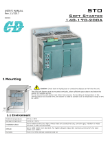
1.6 Dimensions
1. Mechanical Installation (continued)

Synergy Series Soft Start User Manual
MAN-SGY-017. Version 01. 25/07/2016
16
1.6 Dimensions (continued)
1. Mechanical Installation (continued)

Synergy Series Soft Start User Manual
MAN-SGY-017. Version 01. 25/07/2016
17
1.6 Dimensions (continued)
1. Mechanical Installation (continued)
synergy
TM
SGY401 to SGY403

Synergy Series Soft Start User Manual
MAN-SGY-017. Version 01. 25/07/2016
18
1.6 Dimensions (continued)
1. Mechanical Installation (continued)
synergy
TM
SGY501 to SGY505

Synergy Series Soft Start User Manual
MAN-SGY-017. Version 01. 25/07/2016
19
1.7 Mechanical Specification
Mechanical Specifications
Model (SGY-)
101
103
105
107
109
111
113
115
117
Frame Size
1
Heat output (W)
25.5
31.5
40.5
51.0
60.0
78.0
97.5
116
114
Weight kg [lb]
3.0 [6.6]
3.5 [7.7]
Model (SGY-)
201
203
205
301
303
305
307
309
-
Frame Size
2
3
-
Heat output (W)
186
234
270
363
453
542
621
716
-
Weight kg [lb]
5.5
[12.1]
6.5 [14.3]
16.0 [35.3]
21.2 [46.7]
-
Model (SGY-)
401
403
501
503
505
-
Frame Size
4
5
-
Heat output (W)
1830
2166
2500
2880
3240
-
Weight kg [lb]
65 [143.3]
72 [158.7]
-
Model
Models SGY-101 to 309
Ambient Operating Temp.
-20°C [-4°F] to 50°C [122°F] ; above 50°C derate linearly by 4%
of SYNERGY Ie per °C to a maximum of 60°C (140°F)
Transportation and Storage
Temperature
-20°C to 60°C [-4°F to 140°F] continuous
Humidity
max 85% non-condensing, not exceeding 50% @ 40°C [104°F]
Maximum Altitude
1,000m [3281ft] ; above 1000m derate by 1% of synergy I
e
per
100m (328ft) to a maximum altitude of 2,000m (6562ft)
Environmental Rating
Main Circuit: IP00 (IP20 with optional finger guards for sizes 1&2
only); Control Circuit: IP20; No corrosive gases permitted
Model
Models SGY-401 to 503
Ambient Operating Temp.
20°C [-4°F] to 40°C [122°F] ; above 40°C derate linearly by 4% of
SYNERGY Ie per °C to a maximum of 60°C (140°F)
Transportation and Storage
Temperature
20°C [-4°F] to 50°C [122°F] ; above 50°C derate linearly by 4% of
SYNERGY Ie per °C to a maximum of 60°C (140°F)
Humidity
max 85% non-condensing, not exceeding 50% @ 40°C [104°F]
Maximum Altitude
1,000m [3281ft] ; above 1000m derate by 1% of synergy Ie per
100m (328ft) to a maximum altitude of 2,000m (6562ft)
Environmental Rating
Main Circuit: IP00; Control Circuit: IP20; No corrosive gases
permitted
1. Mechanical Installation (continued)

Synergy Series Soft Start User Manual
MAN-SGY-017. Version 01. 25/07/2016
20
Blank Page
/