Page 6
ALLURE
®
QS3 SERIES
RANGE HOOD
If hood is to be installed Non-Ducted:
Purchase a set of (2) Non-Ducted Filters from your local
distributor or retailer and attach them to the aluminum mesh
filters.
NON-DUCTED FILTERS
WARNING: To reduce the risk of electric shock,
disconnect from power supply before cleaning.
Aluminum mesh filters: Clean frequently using hot water and a
mild detergent. Filters are dishwasher safe.
Charcoal filters: Clean filter surfaces frequently with a damp cloth
and a mild detergent. DO NOT immerse filters in water or put in
dishwasher. The special “Clean Sense” feature indicates when the
filter is to be replaced. The blue and yellow strips will blend to green
when it is time to change the filter. The “Clean Sense” feature works
best when facing toward the cooking surface.
To clean hood: Remove filters. Use a damp cloth and a mild deter-
gent to wipe all grease-laden surfaces. Do not use abrasive cloth,
steel wool pads, or scouring powder on the Teflon
®
-coated bottom
cover or on any painted surface. Use care when cleaning blower
wheel - it must not become bent or misaligned. DO NOT ALLOW
WATER TO ENTER MOTOR. Make sure all surfaces are completely
dry before re-installing filters and restoring power.
Motor is permanently lubricated. Do not oil or disassemble motor.
Teflon
®
is a registered trademark of DuPont.
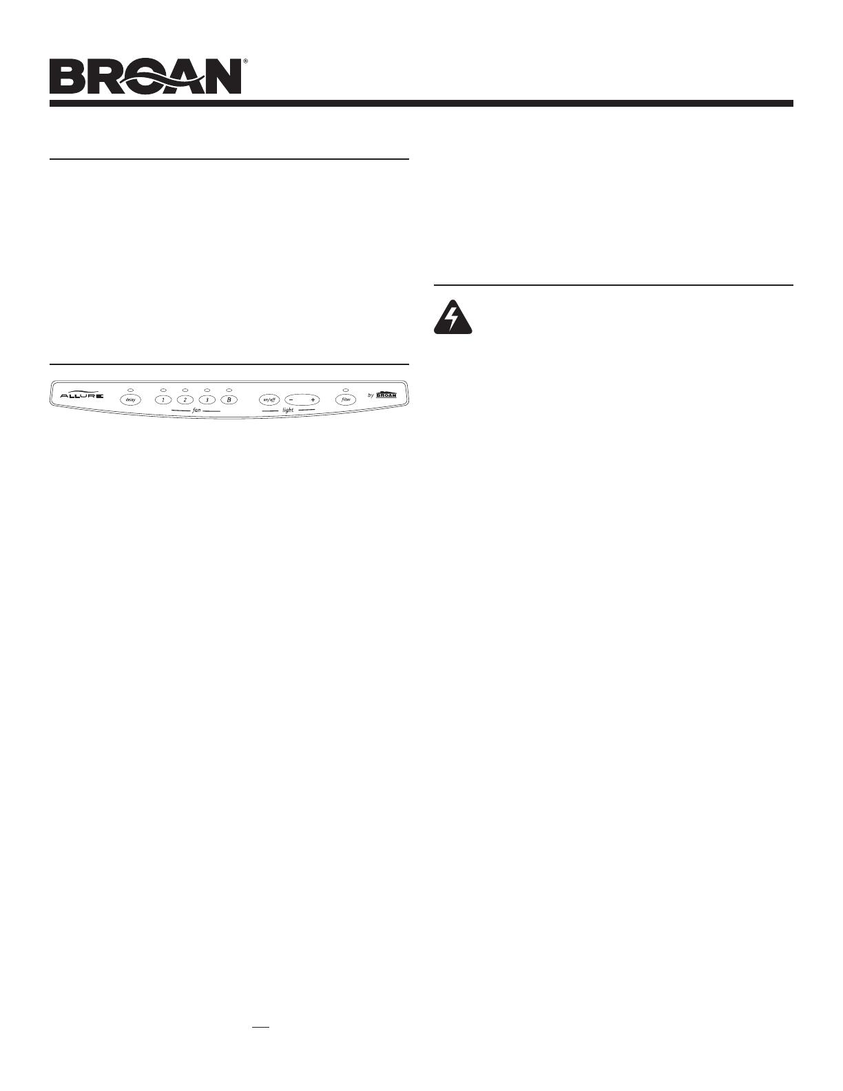
OPERATION
CLEANING
Fan: 4 push button switches. Push any button to select one of the
four fan speeds. Press another button to change fan speed. Push the
same button to turn fan off. A light above each fan button indicates
the fan speed.
Lights: Press “on/off” button and lights will come on at their previ-
ous light level. Press button again to turn lights off. To increase light
level, press the “+” button. To reduce light level, press the “-” button.
There are 3 light levels to select.
Delay Off: While fan is running, press the “delay” button to allow the
fan to run for 10 minutes and then turn itself off.
Filter Change Indicator: The light above “filter” will come on when
it is time to clean your grease filters or check your non-ducted filters.
After replacing the cleaned, or new filters, press the “filter” button to
turn off the indicator light.
Heat Sentry System: Your range hood is equipped with an ad-
vanced Heat Sentry system.
The advanced Heat Sentry system monitors temperature and au-
tomatically adjust the fan to the appropriate setting.
1) If the fan is on, the Heat Sentry system will increase the fan setting
when the temperature is elevated. If the temperature continues
to rise, the Heat Sentry system will continue to increase the fan
setting until the temperature is stabilized or reduced. The flashing
light above the fan button shows the Heat Sentry system fan set-
ting. Once the temperature has reduced, the Heat Sentry system
will change the fan to the original setting.
2) If the fan is on or off, the Heat Sentry system will automatically
turn the fan on at its highest speed when the temperature is above
normal. When the Heat Sentry system is on, the light above the
fan button B (Boost) will flash on and off. After the temperature
has lowered to normal, the fan will change to the setting prior to
the Heat Sentry turning on.
Fuse: The hood control contains a fuse to protect it from power
surges. If the fuse has opened (blown), the green fan-level indicators
will operate properly when the fan buttons/switches are pressed - but
the fan and lights will not turn on.
The fuse is a 5 x 20 mm, 10 Amp, Fast-Acting, 125V (min.). Common
manufacturer and part numbers are: Littlefuse, 217010; Bussmann,
GMA10A; Wickmann, 1942100. Radio Shack, Digikey (1-800-344-
4539), and most electronic supply stores have them in stock.
To replace the fuse:
1. Disconnect power at service entrance.
2. Remove filters, bottom panel, light wire harness, and air chute.
3. Remove and inspect fuse. If it is not open (blown), additional
diagnostics need to be done.
NOTE: For models that are installed in the non-ducted mode,
the most effective operation is achieved at speeds 1 and
2. These speeds provide the most efficient and quiet
operation during cooking, while maximizing the benefits
of the recirculating filtration system.
4. Install new fuse.
5. Re-assemble air chute, light wire harness, bottom panel, and
filters.
6. Turn on power and check hood/control operation.


