Page is loading ...

Operator's Manual
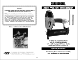
CRRFTSMRN
18 Gauge
%- 1112" Length Brad Nails
_12- 1_12" Length, _14"Crown Staples
COMBINATION NAILER/STAPLER
Model No.
351.184540
CAUTION" Read and follow
all Safety Rules and Operating
Instructions before First Use
of this Product.
• Safety
• Operation
• Maintenance
• Parts List
Sears, Roebuck and Co., Hoffman Estates, IL 60179 U.S.A.
15071.03 Draft (04/02/01)

Warranty ....................................... 2
Safety Rules .................................... 2
Operation .................................... 2-4
Maintenance .................................... 4
Troubleshooting ................................. 5
Parts Illustration and List ......................... 6-7
FULL ONE YEAR WARRANTY ON CRAFTSMAN
AIR-DRIVE TOOLS
If this Craftsman air-drive tool fails due to a defect in material
or workmanship within one full year from the date of purchase,
return it to the nearest Sears Service Center in the United
States, and Sears will repair it free of charge.
If this air-drive toot is used for commercial purposes, this
warranty applies for only 90 days from the date of purchase.
This warranty gives you specific legal rights and you may also
have other rights which vary from state to state.
Sears, Roebuck and Co., Dept. 817WA, Hoffman Estates, IL
60179
• Air toot operators and all others in work area should
always wear safety goggles complying with United States
ANSI Z87.1 to prevent eye injury from fasteners and flying
debris when loading, operating or unloading this tool.
° Never exceed operating pressure of 100 PSI.
° Always keep hands and body away from the fastener dis-
charge area when air supply is connected to tool.
° Always disconnect tool from air supply when servicing or
adjusting tool and when tool is not in use.
° Do not operate when contact trip is not in contact with
work.
° Never load the tool until you are ready to use it.
° Never depress tool trigger when loading.
° Always load with nose of tool pointing away from you and
others.
° Never point tool at yourself or others.
° Never carry tool with trigger depressed.
° Do not use oxygen, combustible gas or high pressure
compressed gas as the air supply for the tool.
° Always use tool at safe distance from other people in work
area.
° Do not attempt to discharge fastener into hard or brittle
materials such as concrete, steel or tile.
° Do not connect female quick-disconnect coupling to tool
side of air line.
° Connect male, free-flow nipple to tool side of air line so
that tool is depressurized when hose is disconnected.
° Do not use a hose swivel with this tool.
° Use Sears recommended fasteners only.
2
DESCRIPTION
The Craftsman 18 Gauge Combination Nailer and Stapler
drives brads from %" to 1W' tong and 1/4"crown staples from 1/2
to 11/2"long. Die cast aluminum body with textured grip mini-
mizes operator fatigue. Large capacity, easy loading magazine
features positive, quick action latch. Safety feature disables
toot unless contact trip is pressed against workpiece. Tapered
nosepiece provides operator with greater visibility for precise
fastener placement. Rigid nosepiece reduces jamming. The 18
Gauge Combination Nailer and Stapler is excellent for mold-
ing, furniture making, picture framing, and upholstery.
SPECIFICATIONS
Capacity .................. 110 brad nails or 110 staples
Fastener size ................. 18 gauge (.049" x .040")
Nail lengths ............................... % to 11/2"
Staple lengths ............................. 1/2to 11/2"
Operating pressure ....................... 60-100 PSI
Air inlet .................................. W' N.RT.
Length ...................................... 9W'
Height ....................................... 9%"
Width ....................................... 21/1_''
Weight .................................... 2.6 lbs.
BRAD NAILS
18341 .................... 18 gauge brad nails, %" long
18342 .................... 18 gauge brad nails, 1" long
18343 ................... 18 gauge brad nails, 11/4"long
18360 ................... 18 gauge brad nails, 11/2"long
STAPLES
18333 ............................ 1/41tcrown, W' long
18334 ............................ 1/4"crown, 3/4"long
18336 ............................ 1/4"crown, 7/8"long
18371 ............................ 1/4"crown, 1" long
18372 ........................... 1/4"crown, 1W' long
18373 ........................... 1/4"crown, 11/4"long
18374 ........................... 1/4"crown, 11/=,,long
AIR SUPPLY LINE
Refer to Figure 1 (page 3).
• The air tool operates on compressed air at pressures from
60 to 100 PSI.
• Never exceed maximum pressure.
Air Delivery Required: 0.71 SCFM @ 90 PSI
(30 shots per minute).
WARNING: Keep hands and body away from discharge area
of tool when connecting air supply. Always disconnect tool
from air supply when servicing or adjusting tool and when tool
is not in use.
• Air operated tools require clean, dry, lubricated com-
pressed air to ensure top performance, low maintenance
and long life.
• Dirt and abrasive materials present in all air lines will dam-
age tool O-rings, valves and cylinders.
• Moisture wilt reduce tool performance and life if not
removed from compressed air.

• Afilter-regulator-lubricatorsystemisrequiredandshouldbe
locatedasclosetotoolaspossible(seeFigure1,page3).
Adistanceoflessthan15feetisrecommended.
° Keepairfilterclean.Adirtyfilterwiltreducetheairpressure
tothetootcausingareductioninpowerandefficiency.
° Theairsupplysystemmustbeabletoprovideairpressure
of60to100poundspersquareinchattool.
° Allhosesandpipesintheairsupplysystemmustbeclean
andfreeofmoistureandforeignparticles.
° Donotmountswivelconnectorinairsupplyline.
° Theairpressureshouldbeproperlyregulated.
° Differentworkpiecematerialsanddifferentfastenerlengths
willrequiredifferentoperatingpressure.
° Besureallconnectionsinairsupplysystemaresealedto
preventairloss.
° Neverconnectafemalequick-disconnectcouplingtothe
toolsideofairlineconnection.Amale,free-flowcoupling
shouldbeconnectedtothetoolsideofairlineconnection.
WARNING:Thefemalecouplingprovidesasealpreventing
lossofcompressedairfromcompressortankwhendiscon-
nectedfrommalecoupling.Ifconnectedtotoolsideofair
supply,thefemalecouplingcouldsealacompressedair
chargeinthetoolwhichcoulddischargeifthetooltriggeris
actuated.
2FootHoseWhip--
\
Male Quick-Disconnect
Figure 1 - Air Supply Line
Filter- Regulator- Lubricator
Female Quick-Disconnect
LOADING
Refer to Figures 2 & 5 (pages 3 and 6).
WARNING: Disconnect toot from air supply. Always toad with
nose of tool pointing away from you and others. Always wear
safety goggles that comply with United States ANSI Z87.1.
NOTE: For best results, use Sears fasteners only.
• Depress latch (Fig. 5, No. 51) and slide magazine cover
(Fig. 5, No. 49) backwards (see Figure 2). Insert fasteners
into magazine. Position nails at bottom of magazine with
heads toward top of tool (see Figure 2A).
• Position staples crown at top of magazine with tips toward
bottom of tool (see Figure 2B)
• Do not toad nails and staples together when driving fas-
teners.
• Slide magazine cover forward over magazine until latch
snaps into place, locking magazine cover.
NAILING AND STAPLING OPERATION
Refer to Figures 3 & 5 (pages 3 and 6)
WARNING: Never operate tool unless contact trip is in con-
tact with workpiece. Do not operate tool without fasteners or
damage to tool may result. Never fire fasteners into the air
because fasteners may injure operator or others and damage
to tool may result.
• The air tool is equipped with a contact trip safety mecha-
nism (see Figure 3) that disables tool unless contact trip is
pushed against work. Hold body firmly and press contact
trip on workpiece where fastener is to be applied. Pull
trigger to drive fastener into workpiece.
• The tool can also be operated by holding trigger
depressed and pushing contact trip against workpiece.
This operating procedure provides rapid-fire fastener
driving. Never operate tool unless contact trip is in
contact with workpiece.
Depress
Trigger
A -Loading Brad Nails
Trigger
Depressed
B -Loading Staples
Figure 2 -Loading
Figure 3 -Contact Trip Operation
3

The tool is equipped with a push-button switch that can
change the operating mode from rapid-fire to single fire.
When the red stop button (Fig. 5, No. 31) is pushed in from
the fastener loading side, the tool will fire one fastener only.
Tofire the next fastener, the trigger (Fig. 5, No. 29) must be
released.
OPERATING PRESSURE
• Use only enough air pressure to perform the operation. Air
pressure in excess of that which is required will make the
operation inefficient and may cause premature wear or
damage to the tool.
• Determine minimum air pressure required by driving some
test fasteners into the workpiece. Set air pressure so that
test fasteners are driven down flush with the work surface.
Fasteners driven too deep may damage workpiece.
EXHAUST DEFLECTOR
Refer to Figures 4 & 5 (pages 4 and 6).
• Exhaust deflector can be positioned to point in any direction
(full 360° movement). Reposition deflector (Fig. 5, No. 1) by
grasping firmly and rotating to the desired position.
Rotate Deflector
Figure 4 - Exhaust Deflector Adjustment
Refer to Figure 5 (page 6).
LUBRICATION
Lubricate tool daily with quality air tool oil. If no air line lubri-
cator is used, place five to six drops of oil into air inlet cap
(Fig. 5, No. 38) of tool every day.
MAGAZINE AND PISTON-RAM
• Keep magazine and nose of tool clean and free of any dirt,
lint or abrasive particles.
The tip of the ram (Fig. 5, No. 13) can become dented or
rounded over time.
• Square off the tip of the ram with a clean, fine hand file to
extend the life of the ram and tool. Fastener firing wilt be
more consistent if the ram tip is kept clean and square.
SAFETY MECHANISM
Inspect contact trip safety mechanism daily for proper opera-
tion. Do not operate tool if mechanism is not operating
properly.
With the red push-button switch in the rapid-fire mode, per-
form the following procedures to test safety mechanism:
• Leave trigger untouched while pushing contact trip into
workpiece. Tool must not fire.
• Pull trigger while contact trip is clear of work and pointed
away from operator and others. Tool must not fire.
• Depress and hold trigger. Push contact trip against work
where fastener is needed. The tool should drive only one
fastener each time the contact trip is pushed against
workpiece.
If contact trip mechanism does not operate properly,
repair tool immediately through Sears Service Center.
Replace any damaged or missing parts. Use the parts list to
order parts.
REBUILD KITS
Rebuild kits are available as spare parts, (see page 7). Tools
should be rebuilt if tool fails to operate properly after extended
use. See troubleshooting to determine required replacement
parts.
Disconnect tool from air supply before attempting repair
or adjustment.
NOTE: When replacing O-rings or cylinder, lubricate with air
tool oil before assembly.
4

SYMPTOM POSSIBLE CAUSE(S) CORRECTIVE ACTION
Trigger cap leaks air 1. O-ring damaged 1. Check and replace damaged O-ring (Fig. 5, No. 24)
2. Valve stem, seal or O-rings damaged 2. Check and replace damaged stem, seal or O-rings
(Fig. 5, Nos. 19, 22, 23 and 24)
Cap leaks air 1. Cap bolts loose 1. Tighten bolts (Fig. 5, No. 2)
2. Damaged O-ring or gasket 2. Check and replace damaged O-ring or gasket
(Fig. 5, Nos. 5 and 7)
Nose leaks air 1. Damaged cylinder O-ring 1. Check and replace damaged O-ring (Fig. 5, No. 16)
2. Damaged bumper 2. Check and replace damaged bumper (Fig. 5, No. 17)
3. Ram guide damaged 3. Check and replace guide (Fig. 5, No. 18)
Tool will not operate 1. Insufficient air supply 1.
2. Damaged or worn head valve O-rings 2.
Tool operates slowly
or loses power
Tool skips fasteners or
inconsistent operation
3. Damaged head valve spring
4. Head valve binding in cap
5. Insufficient lubrication
1. Damaged head valve spring
2. Damaged or worn O-rings
3. Damaged trigger assembly
4. Build-up on ram
5. Cylinder not sealed on bumper
properly
6. Insufficient air supply
7. Insufficient lubrication
8. Head valve poorly lubricated
1. Worn or damaged bumper
2. Build-up on ram or nose
3. Insufficient air supply
4. Damaged or worn piston O-ring
5. Damaged magazine springs
6. Magazine-nose bolts loose
7. Fasteners too short
8. Damaged fasteners
9. Incorrect fastener size
10. Cap leaks
11. Damaged trigger valve seal and
O-rings
12. Bent or damaged ram
13. Dirty magazine
14. Damaged or worn magazine
15. Insufficient lubrication
Check air supply
Replace damaged or worn O-rings
(Fig. 5, Nos. 7 and 10)
3. Replace damaged spring (Fig. 5, No. 6)
4. Clean and lubricate cap and head valve
(Fig. 5, Nos. 4 and 9)
5. Place five or six drops of air tool oil into inlet cap
1. Check and replace damaged spring (Fig. 5, No. 6)
2. Check and replace damaged or worn O-rings
3. Check and replace trigger assembly
4. Clean piston/ram assembly (Fig. 5, No. 13)
5. Disassemble cylinder and assemble properly
6. Check air supply
7. Place five or six drops of air tool oil into inlet cap
8. Disassemble head valve (Fig. 5, No. 9),
clean, lubricate, and assemble properly
1. Check and replace bumper (Fig. 5, No. 17)
2. Clean and lubricate piston/ram assembly
(Fig. 5, No. 13) and inside of nose cover (Fig. 5, No. 43)
3. Check air supply
4. Check and replace O-ring (Fig. 5, No. 14)
5. Check and replace spring (Fig. 5, No. 47)
6. Align nose with magazine and tighten bolts
(Fig. 5, No. 42)
7. Use Sears recommended fasteners only
8. Discard damaged fasteners
9. Use Sears recommended fasteners only
10. Tighten cap bolts (Fig. 5, No. 2). Check and replace
damaged cap O-ring (Fig. 5, No. 7) or gasket
(Fig. 5, No. 5)
11. Check and replace damaged seal and O-rings
(Fig. 5, Nos. 19, 23 and 24)
12. Check and replace damaged piston/ram assembly
(Fig. 5, No. 13)
13. Clean magazine and lubricate with air tool oil
14. Check and replace magazine (Fig. 5, No. 44)
15. Place five or six drops of air tool oil into inlet cap
(Fig. 5, No. 38)
5

Model 351.184540
Figure 5 - Replacement Parts Illustration For Combination Nailer/Stapler
I
8_
10-_-._.. 0
31
27
18
23 32
59
48
/
38
/
58
45
49
6

KEY
NO.
1
2
3
4
5
6
7
8
9
10
11
12
13
14
15
16
17
18
19
2O
21
22
23
24
25
26
27
28
29
30
31
32
33
34
A
PART NO. DESCRIPTION
15828.00
04462.00
STD852005
15829.00
04195.00
04210.00
06451.00
06436.00
04302.00
04303.00
04304.00
06909.00
15830.00
04436.00
04465.00
04309.00
04412.00
04487.00
06136.00
04324.00
04325.00
04326.00
04318.00
04327.00
04328.00
04329.00
06437.00
15072.00
15831.00
04323.00
04319.00
04320.00
16355.00
06086.00
Deflector
5-0.8 x 42mm Socket Head Bolt
5mm Lock Washer
Cap
Gasket
Spring
14.8 x 2.4 O-Ring
Spacer
Head Valve Piston
33.5 x 2mm O-Ring
Collar
44 x 1.8mm O-Ring
Piston Ram Assembly
22.4 x 3.1mm 0-Ring
Cylinder
31.5 x 1.8mm O-Ring
Bumper
Ram Guide
8.8 x 1.9mm O-Ring
Trigger Valve Head
Spring
Valve Stem
2.5 x 1.4mm O-Ring
9.8 x 1.9mm O-Ring
Trigger Cap
Spring
1.2 x 2.6mm O-Ring
1 x 8mm Spring Pin
Trigger Assembly
Clevis Pin
Stop Button
Throttle
Body
4-0.7 x 8mm Socket Head Bolt
QTY.
1
4
6
1
1
1
1
1
1
1
1
1
1
1
1
1
1
1
1
1
1
1
4
1
1
1
1
1
1
1
2
1
1
5
Standard hardware item available locally
Not Shown
Recommended Accessories
A Gauge Brad Nails, %" Long 18341
A Gauge Brad Nails, 1" Long 18342
A Gauge Brad Nails, 11/4"Long 18343
A Gauge Brad Nails, 11/2"Long 18360
A Staple, %" Crown, 1121tLong 18333
A Staple, %" Crown, 3/4"Long 18334
A Staple, %" Crown, 7/8"Long 18336
A Staple, %" Crown, 1" Long 18371
A Staple, %" Crown, 1%" Long 18372
A Staple, %" Crown, 1%" Long 18373
A Staple, %" Crown, 11/2"Long 18374
KEY
NO. PART NO.
35 06349.00
36 15832.00
37 04316.00
38 04440.00
39 00814.00
40 15833.00
41 15834.00
42 16443.00
43 15835.00
44 15836.00
45 15837.00
46 15838.00
47 15839.00
48 05993.00
49 15116.00
50 15117.00
51 15118.00
52 16354.00
53 15122.00
54 04332.00
55 15120.00
56 15121.00
57 STD852004
58 05809.00
59 07482.00
60 STD851005
61 04343.00
62 04469.00
63 04345.00
64 16604.00
A 16442.00
A 15071.03
DESCRIPTION
5-0.8mm Fiber Hex Nut
Bracket
40 x 3mm O-Ring
Inlet Cap
5-0.8 x 16mm Socket Head Bolt
Nose Plate
Guide Bar
4-0.7 x 16mm Socket Low
Head Bolt
Nose
Magazine
Wear Rod
Pusher
Spring
3 x 18mm Spring Pin
Magazine Cover
Spring
Latch
2.5 x 20mm Spring Pin
Contact Trip
Cover Plate
End Cover
Plate
4mm Lock Washer
4-0.7 x 6mm Socket Head Bolt
5-0.8 x 18mm Socket Head Bolt
5mm Flat Washer
Trip Lever
Nose Cover
Shoulder Screw
Bushing
Storage Case
Operator's Manual
QTY.
1
1
1
1
2
1
1
2
1
1
1
1
1
1
1
1
1
1
1
1
1
1
3
1
1
1
1
1
2
1
1
1
Rebuild Kits
A 15123.00 Piston-Ram Rebuild Kit 1
Fig. 5, Nos. 13, 14 and 18
A 15124.00 Cylinder Rebuild Kit 1
Fig. 5, Nos. 12, 15, 16 and 17
A 03097.00 Trigger Assembly Rebuild Kit 1
Fig. 5, Nos. 19, 22, 24, and two 23
A 15126.00 Head Valve Rebuild Kit 1
Fig. 5, Nos. 5, 7 and 10
7

In U.S.A. or Canada
for in-home major brand repair service:
Call 24 hours a day, 7 days a week
1-800-4-MY-HOME sM(1-800-469-4663)
Para pedir servicio de reparacion a domicilio - 1-800-676-5811
Au Canada pour tout le service - 1-877-LE-FOYER sM(1-877-533-6937)
For the repair or replacement parts you need"
Call 6 a.m. - 11 p.m. CST, 7 days a week
PartsDirect
1-800-366-PART (1-800-366-7278)
www.sears.com/partsdirect
Para ordenar piezas con entrega a domicilio - 1-800-659-7084
For the location of a Sears Service Center in your area:
Call 24 hours a day, 7 days a week
1-800-488-1222
To purchase or inquire about a Sears Maintenance Agreement:
Call 7 am - 5 pm CST, Monday- Saturday
1-800-827-6655
SEARS
HomeCentral
/