GE NVLR223GG7WW Installation guide
- Category
- Tumble dryers
- Type
- Installation guide

Inst II "
Inst uct"
GasDryer
I If you have any questions, carl 1-800-GECARES (US) or 1-800-361-3400 (Canada)
or Visit our Web site at: www. GEAppliances.com
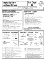
BEFOREYOU BEGIN
Read these instructions completely and carefully.
IMPORTANT -Savethese
instructions for local inspector's use.
IMPORTANT =Observeall
governing codes and ordinances.
Note to Installer - Be sure to leave these instructions with
the customer
Note to Customer - Keep these instructions with your Use
and Care Book for future reference.
This dryer must be exhausted to the outdoors.
Before the old dryer is removed from service or discarded,
remove the dryer door.
Service Information and the wiring diagram are located in
the control console.
Service of this dryer must be performed by a qualified
installer,service agency, or the gas supplier.
Do not allow children on or in the appliance. Close
supervision of children is necessary when the appliance is
used near children.
TOOLS YOU WiLL NEED
10"ADJUSTABLEWRENCHES(2)
SLIPJOINTPLIERS
FLATBLADESCREWDRIVER
8"PIPEWRENCH
%
LEVEL
FORYOUR SAFETY:
,_kWARNING
• Use only rigid metal or flexible metal 4-in. diameter
ducrwork for exhausting to the outdoors. Never use
plastic or other combustible easy-to-puncture ductwork.
• This appliance must be properly grounded and installed
as described in these instructions.
• Do not install or store appliance in an area where it
will be exposed to water and/or weather.
• The National Fuel Gas Code restricts installations of
gas appliances in garages. They must be 18 in. off the
ground and protected by a barrier from vehicles.
• Install the dryer where the temperature is above 50°F
for satisfactory operation of the dryer control system.
MATERIALS YOU WILL NEED
%
4"DIA,METALELBOW
PIPECOMPOUND
FLEXIBLEGASLINECONNECTOR
4"DIA,METALDUCT
(RECOMMENDED)
4"DIA.FLEXIBLEMETALDUCT
(IFNEEDED)
GLOVES
DUCT SOAPSOLUTION
CLAMPS(2) FORLEAKDETECTION
EXHAUSTHOOD
SAFETYGLASSES DUCTTAPE
Step 1
Step 2
Step 3
Step 4
Step 5
Step 6
Step 7
Verify Your Gas Installation (see section 2).
Prepare the Area and Exhaust for Installation of
New Dryer (see section 1).
Check and Insure the Existing External Exhaust is
Clean (see section 1) and Meets Attached Installation
Specifications.(see section 6)
Remove the Foam Shipping Pads (see section 1).
Move the Dryer to tile Desired Location.
Level Your Dryer (see section 8).
Connect tile Gas Supply (see section 3) and check
for leaks (see section 4).
Step 8 Connect the External Exhaust (see section 7).
Step 9 Connect the Power Supply (see section 5).
Step 10 Check the Operation of the Power Supply, Gas
Connections, and Venting.
Step 11 Place the Owners Manual and the Installation
Instructions in a Location Where They _rill Be
Noticed By the Owner.
For Alcove or Closet Installation see section 9.
For Bathroom or Bedroom Installation see section 10.
For Mobile or Manufactured Home see section 11.

Installation instructions
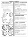
Minimum Clearance Other Than Alcove or Closet Installation
Minimum clearance to combustible surfaces and fox'air opening are: 0 in. clearance both skies and 1in. rear. Consideratkm
must be given to provkte adequate clearance for proper operation and service.
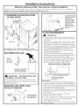
[] PREPARING FOR iNSTALLATiON
OF NEW DRYER
EXTERNAL
DUCT
OPENING
CSA(AGA)APPROVED
NEWFLEXIBLEGAS
LINECONNECTOR
GAS
INLET
PIPE
DUD]
TAPE
4"METALDUCT \
DUCT
TAPE
TIP: Install your dryer before installing your washer.
_[his will allow better access when installing dryer exhaust.
DiSCONNECTiNG GAS
TURNGAS . .__
SHUT-OFF
VALVETOTHE
OFFPOSITION.
DISCONNECTANDDISCARDOLD
FLEXIBLEGASCONNECTOR
ANDOLDDUCTINGMATERIAL.
Z_
WARNING - NEVERREUSE OLD
FLEXIBLE CONNECTORS.
The use of old flexible connectors can cause leaks and
personal injury. Always use new flexible connectors when
installing gas appliances.
REMOVING LiNT FROM WALL
EXHAUST OPENING
WALL
/
INTERNALDUCT CHECKTHATEXHAUST
OPENING OPENS
ANDCLOSESFREELY,
2
TILTTHEDRYERSIDEWAYS
ANDREMOVETHEFOAM
SHIPPINGPADSBY
PULLINGATTHESIDES
ANDBREAKINGTHEM
AWAYFROMTHEDRYER
LEGS,BESURETO
REMOVEALLOFTHE
FOAMPIECESAROUND
THELEGS.
[] GAS REQUIREMENTS
WARNING
. Installation must conform to local codes and ordinances,
or in their absence, the NATIONAL FUEL GAS CODE,
ANSI Z223.
. This gas dryer is equipped with a Valve & Burner Assem-
bly for use only with natural gas. Using conversion kit
WE25X0217, your local service organization can convert
this dryer fox'use with propane (LP) gas. ALL CONVER-
SIONS MUST BE MADE BY PROPERLY TRAINED
AND QUALIFIED PERSONNEL AND IN AC-
CORDANCE WITH LOCAL CODES AND ORDI-
NANCE REQUIREMENTS
. The dryer must be disconnected fl'om the gas supply
piping system during any pressure testing of that system
at a test pressure in excess of 05 PSI (3.4 KPa)
° The dryer must be isolated from the gas supply piping
system by closing the equipment shut-off valve during
any pressure testing of the gas supply piping of test
pressure equal to or less than 05 PSI (3.4KPa).
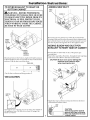
DRYER GAS SUPPLY CONNECTION
2"
I 24/8" 3/8"NPTMALETHREADGASSUPPLY
NOTE:Addtoverticaldimension
thedistancebetweencabinet
bottomtofloor.
GAS SUPPLY
A 1/8-in. National Pipe Taper thread plugged tapping, ac-
cessible for test gauge connection, must be installed imme-
diately upstream of the gas supply connection to the dryer.
Contact your local gas utility should you have questions on
the installation of the plugged tapping.
Supply line is to be 1/2-in. rigid pipe and equipped with an
accessible shut-offwithin 6 ft. of, and in the same room
with, the dryer.
Use pipe thread sealer compound or Teflon tape
appropriate for natural or LP gas.
You must use with this dwer a flexible metal connector listed
connector ANSI Z21.24 / CSA 6.10. The length of the
connect shall not exceed 3 ft.
Connect flexible metal connector to dryer and gas supply.
Open shut-offvalve_

Installation
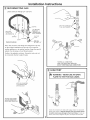
[] RECONNECTING GAS
Listed connector ANSI Z21.24 / CSA 6.10
118" NPT PIPE
NEW METAL PLUG FOR
GAS
FLEXIBLEGAS INLET PRESSURE
LINECONNECTOR
ADAPTER
ELBOW
3/8" NPT
SHUT-OFF
PIPESIZE
ITEMSNOT SUPPLIED --AT LEAST I/2"
Note: The connector and fittings are designed for use only
on the original instaUation and are not to be reused for
another appUance or at another tocation, Keep flare end of
adaptor free of grease, oil and thread seal.ant,
Caution: Use adapters as shown. Connector nuts must not
be connected direcNy to pipe threads.
APPLYPIPECOMPOUND
TOTHEADAPTERAND
DRYERGASINLET.
\
TIGHTEN THE FLEXIBLE
GASLINE USING TWO
ADJUSTABLEWRENCHES.
Instructions
APPLYPIPECOMPOUND
TOALLMALETHREADS.
3
©
TIGHTEN ALL CONNECTIONS
USING TWO ADJUSTABLE WRENCHES.
DO NOT OVERTORQUE GAS CONNECTIONS!
[] LEAK TEST
,_ WARNING - NEVER USE AN OPEN
FLAME TO TEST FOR GAS LEAKS.
OPEN
GASVALVE,
Check all connections for leaks with soapy solution or equivalent.
Apply soap solution. Leak test solution must not contain ammo-
nia which could ceuse damage to the brass fittings. If leaks are
found, close valve, retighten the joint, and repeat the soap tesL

Installation
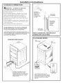
[] ELECTRICAL CONNECTION
iNFORMATiON
WARNING- TO REDUCE THE RISK OF
FIRE, ELECTRICAL SHOCK, AND PERSONAL
INJURY:
DO NOT USE AN EXTENSION CORD OR AN
ADAPTER PLUG WITH THIS APPLIANCE.
Dryer must be electrically grounded in accordance with
local codes and ordinances, or in the absence of local
codes, in accordance with the NATIONAL ELECTRI-
CAL CODE, ANSI/NFPA NO. 70.
ELECTRICAL REQUIREMENTS
This appliance must be supplied with 120V, 60Hz, and connected
to a properly grounded branch circuit, protected by a 15- or 20-
amp circuit breaker or time-delay fuse. If electrical supply provid-
ed does not meet the above specifications, it is reconnnended that
a licensed electrician install an apt)roved outlet.
_WARNING - THIS DRYER IS EQUIPPED
A THREE-PRONG (GROUNDING) PLUG FOR
YOUR PROTECTION AGAINST SHOCK
HAZARD AND SHOULD BE PLUGGED
DIRECTLY INTO A PROPERLY GROUNDED
THREE-PRONG RECEPTACLE. DO NOT CUT
OR REMOVE THE GROUNDING PRONG
FROM THIS PLUG.
ENSURE PROPER GROUND EXISTS BEFORE USE.
(-
IFLOCALCODESPERMIT,
ANEXTERNALGROUNDWIRE
(NOTPROVIDED},WHICHMEETS
LOCALCODES,MAYBEADDED
BYATTACHINGTOTHEGREEN
GROUNDSCREWONTHEREAR
OFTHEDRYER,ANDTOA GROUNDED
METALCOLDWATERPIPEOROTHER
ESTABLISHEDGROUND.
instructions
[] EXHAUST iNFORMATiON
A
_WARNING - USE ONLY METAL 4-IN. DUCT.
DO NOT USE DUCT LONGER THAN SPECIFIED
IN THE EXHAUST LENGTH TABLE.
Exhaust longer than specified will:
• Increase the drying times and the energy cost.
" Reduce the dryer life.
• Accunmlate lint, creating a potential fire hazard.
The correct exhaust installation is your responsibility.
Problems due to incorrect installation a,,e not covered
by the warranty.
The MAXIMUM ALLOWABLE length of the exhaust system
depends upon the type of duct, number of turns, the type of
exhaust hood (wall cap), and all conditions noted below-. Both
rigid and flexible metal duct are shown in the table below:
No. of 90°
Elbows
0
1
2
3
4
5
EXHAUST LENGTH
RECOMMENDED MAXIMUM LENGTH
Exhaust HoodTypes
Recommended
Rigid Flexible
Metal Metal
150 Feet 55 Feet
135 Feet 52 Feet
125 Feet 49 Feet
115 Feet 48 Feet
105 Feet 43 Feet
95 Feet 40 Feet
Use onlyfor short
run installations
4" DIA.
[_2-1/2"
Rigid Flexible
Metal Metal
125 Feet 45 Feet
115 Feet 42 Feet
105 Feet 39 Feet
95 Feet 35 Feet
85 Feet 33 Feet
75 Feet 30 Feet
4
If using flexible metal duct, please refer to page 6.
EXHAUST SYSTEM CHECK LiST
HOOD OR WALL CAP
•Terminate in amanner to prevent back drafts or entry of birds or
other wildlife.
•Termination should present minimal resistance to the exhaust air flow
and should require little or no maintenance to prevent clogging.
•Never install a screen in or over the exhaust duct.
•Wall caps must be installed at least 12in. above ground level or any other
obstruction with the opening pointed down.
•If roof vents or louvered plenmns are used, they must be equivalent to a
4-in. dampened wall cap in regard to resistance to air flow, prevention of
back drafts, and maintenance required to prevent clogging.
SEPARATION OF TURNS
Fox'best perfbrmance, separate all turns by at least 4 fL of straight duct,
including distance between last turn and dampened wall cap.
TURNS OTHER THAN 90°
• One turn of 45o or less may be ignored.
o
•Two 45 turns should be treated as one 90oturn.
o o
•Each turn over 45 should be treated as one 00 turn.
SEALING OF JOINTS
"All joints should be tight to avoid leaks. The male end of each section of
duct must point away fi'om the dryer.
*Do not assemble the ductwork with fasteners that extend into the duct.
They will serve as a collection point fbr lint.
"Duct joints should be made air-and moisture-tight by wrapping the
overlapped joints with duct tape.
"Horizontal runs should slope down towm'ds outdoors 1/2 inch pet"fbot.
INSULATION
•Duct work that runs through an unheated area or is near air conditioning
should be insulated to reduce condensation and lint build up_

Installation
[] EXHAUST CONNECTION
,_WARNING - TO REDUCE THE RISK
OF FIRE OR PERSONAL INJURY:
This dryer must be exhausted to the outdoors.
Use only metal duct.
Do not terminate exhaust in a chimney, any gas vent,
under an enclosed floor (crawl space), or into an attic.
The accumulated lint could create a fire hazard.
Provide an access for inspection and cleaning of the
exhaust system, especially at turns. Inspect and clean at
least once a year.
Never terminate the exhaust into a common duct with a
kitchen exhaust. A combination of lint and grease could
create a fire hazard.
Do not obstruct incoming or exhausted air.
WE RECOMMEND THAT YOU INSTALL YOUR DRYER
BEFOREYOUR WASHER. THIS WILL PERMIT DIRECT
ACCESS FOR EASIEREXHAUST CONNECTION
THIS DRYERCOMES READY FORREAREXHAUSTING. IF
SPACEIS LIMITED, USE THE INSTRUCTIONS IN SECTION
12 TO EXHAUST DIRECTLYFROM THE LEFTSIDE OR
BOTTOM OF THE CABINET.
STANDARD REAR EXHAUST
WESTRONGLYRECOMMENDTHEUSEOF
RIGIDMETALEXHAUSTDUCT.IFUSING
FLEXABLEMETALDUCT,CUTITTOTHEPROPER
LENGTHANDAVOIDBUNCHINGOFTHEDUCT
BEHINDTHEDRYER.
Instructions
FORSTRAIGHT
LINEINSTALLATION,
CONNECTTHE ELBOWHIGHLY
DRYEREXHAUST -_ RECOMMENDED.
TOTHEWALLUSING
DUCTTAPE,
ELBOWHIGHLY
RECOMMENDED,-
RECOMMENDED
CONFIGURATION
TOMINIMIZE
EXHAUST
BLOCKAGE,
NOTE: ELBOWS WILL PREVENT DUCT
KINKING AND COLLAPSING.
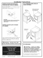
[] LEVELING DRYER
LEVEL
FRONT-TO-BACK.
_. LEVEL
SIDE-T0-SIDE
4LEVELINGLEGS
STANDTHEDRYERUPRIGHTNEARTHE
FINALLOCATIONANDADJUSTTHE4LEVELING
LEGSTOMATCHTHEHEIGHTOFYOURWASHER,
ADJUSTTHE2ANTI-TIPLEGSTOCONTACT
THEFLOOR.
2ANTI-TIPLEGS

Installation instructions
USING FLEXIBLE METAL DUCTS
If rigid all metal duct cammt be used, then flexible all metal
venting cart be used, but it will redtlce the maximum
recommended duct length. In special installations when it is
impossible to make connection with the above recomlnendations,
then UL listed clothes dryer transition duct may be used as
transition venting between the dryer and wall connection only. The
use of this ducting will aflect dry time.
If flexible transition duct is necessary, the fbllowing directions must
be followed.
• Use the Shortest Length Possible.
• Stretch the Duct to Its Maximmn Length.
• Do Not Crush or Collapse.
• Never Use _lYansition Duct Inside the Wall or
Inside the Dryer.
• Avoid Resting the Duct on Sharp Objects.
• Venting Must Conform to Local BuiMing Codes.
|
ELBOWHIGHLY
RECOMMENDED
ELBOWSHIGHLY
)(
DONOTUSE
EXCESSIVE
t
D0,0T\
_. CRUSH
FLEXIBLE
N EXHAUST
_ AGAINST
[] ALCOVE OR CLOSET INSTALLATION
o If yore' dryer is approved for installation in an alcove or
closet, it will be stated on a label on the dryer back.
o The dryer MUST be vented to the outdoors. See the
EXHAUST INFORMATION section.
o Mininmm clearance between dryer cabinet and adjacent
walls or other surfaces is:
0 in. either side
3 in. fl'ont and rear
o Minimum vertical space from floor to overhead cabinets,
ceiling, etc. is 52 in.
o Closet doors must be louvered or otherwise ventilated and
mtlst contain a minimum of 60 sq in. of open area equally
distribmed. If the closet contains both a washer and a
dryer, doors nmst contain a mininmm of 120 sq in. of open
area equally distributed
o The closet sbotfld be vented to the omdoors to prevent gas
pocketing in case of a gas leak in the supply line.
o No other tirol-burning appliance shall be installed in the
same closet with the dryer.
[] BATHROOM OR BEDROOM
INSTALLATION
6
o The dryer MUST be vented to the outdoors, See
EXHAUST INFORMATION section 6
o The installation nmst conform with local codes or, in the
absence of local codes, with the NATIONAL FUEL GAS
CODE, ANSI Z223
[] MOBILE OR MANUFACTURED
HOME INSTALLATION
oInstallation must conform to the MANUFACTURED
HOME CONSTRUCTION & SAFETY STANDARD,
TITLE 24, PART 32-80 or, when such standard is not
applicable, with AMERICAN NATIONAL STANDARD
FOR MOBILE HOME, NO. 501B,
oThe dryer MUST be vented to the outdoors with the
termination securely fastened to the mobile home
structure. (See EXHAUST INFORMATION section 6.)
oThe vent MUST NOT be terminated beneath a mobile or
manufactm'ed home.
oThe vent duct material MUST BE METAL.
*KIT 14-D346-33 MUST be used to attach the dryer
securely to the structure
oThe vent MUST NOT be connected to any other duct,
vent, or chimney.
oDo not use sheet metal screws or other refastening
devices which extend into the interior of the exhaust vent.
oProvide an opening with a free area of at least 25 sq, in.
for introduction of outside air into the dryer room.

Installation Instructions:
[] DRYER EXHAUST TO RIGHT OR
BOTFOM CABINET
I--
IAkWARNING-BEFORE PERFORMING
THIS EXHAUST INSTALLATION, BE SURE
TO DISCONNECT THE DRYER FROM ITS
ELECTRICAL SUPPLY. PROTECT YOUR
HANDS AN DAR MS FROM S HARP EDGES
WHEN WORKING INSIDE TH E CABINET.
BE SURE TO WEAR GLOVES
REMOVE
SCREW
ANDSAVE.
REMOVE
DESIRED
KNOCKOUT
(0NEONLY).
Detach and remove the bottom, right or left side knockout
as desired. Remove the screw inside the dryer exhaust duct
and save. Pull the duct out of the drye_
FIXINGHOLE
B A
4 9"
Cut the duct as shown and keep portion A.
TAB LOCATION
BENDTAB
UP45o
Through the rear opening, locate the tab in the middle of
the appliance base. Lift the t:ab to about 45 using a fiat
blade screwdriver
7
ADDING NEW DUCT
FIXING
HOLE
PORTION"A"
Reconnect the cut portion (A) of the duct to the blower
housing. Make sure that the shortened duct is aligned with
the tab in the base. Use the screw saved previously to secure
the duct in place through the tab on the appliance base.
ADDING ELBOW AND DUCT FOR
EXHAUST TO RIGHT SIDE OF CABINET
• Preassemble 4" elbowwith 4" duct. Wrap duct tape
around joint.
• Insert duct assembly, elbow first, through the side opening
and connect the elbow to the dryer internal duck
CAUTION: Be sure not to pull or damage the
electrical wires inside the dryer
when inserting the duct,
l_ _i EXHAUST CAN
DUCT/ "-,4,/ RIGHTSIDE
TAPE
•Apply duct tape as shown on thejoint between the dryer
internal duct and the elbow.
DUCT
CAUTION:
Internal duct joints must be
-_ secured with tape, otherwisethey may separate and cause
a safety hazard.

Installation
ADDING ELBOW FOR EXHAUST
THROUGH BOTTOM OF CABINET
• Insert the elbow through tile rear opening and connect it to
tile dryer internal duct.
• Apply duct tape on the joint between the dryer internal
duct and elbow, as shown on page 7.
CAUTION:
internal duct joints must be secured with tape,
otherwise they may separate and cause a
safety hazard.
ADDING COVER PLATE TO REAR
OF CABINET
PLATE
(KITWE1M454)
Connect standard metal elbows and ducts to complete the
exhaust system. Cover back opening with a plate (Kit
WE1M454) available from your local service provider.
Place dryer in final location.
I '_WARNING- NEVER LEAVE THE I
BACK OPENING WITHOUT THE PLATE.
For Questions on Installation, Call: 1-800-626-2000 (US) or
500A420P003 1-800-361-3400 (Canada). Pub. # 31-16139 8
instructions
[] CHANGING DIRECTION OF
DOOR OPENING
REMOVE4
HINGESCREWS.
REMOVE4HOLEPLUGSAND
PLACETHEMINTHEHOLES
ONTHEOPPOSITESIDE.
ROTATEDOOR1800
ANDREINSTALL.
[] SERViCiNG
_{k WARNING- LABEL ALL WIPES
PRIOR TO DISCONNECTION WHEN
SERVICING CONTROLS. WIRING
ERRORS CAN CAUSE IMPROPER AND
DANGEROUS OPERATION AFTER
SERVICING/INSTALLATION.
For replacement parts and other information, refer to
Owner's Manual for servicing phone numbers.

Inst II "
Inst uct"
GasDryer
I If you have any questions, carl 1-800-GECARES (US) or 1-800-361-3400 (Canada)
or Visit our Web site at: www. GEAppliances.com
BEFOREYOU BEGIN
Read these instructions completely and carefully.
IMPORTANT -Savethese
instructions for local inspector's use.
IMPORTANT =Observeall
governing codes and ordinances.
Note to Installer - Be sure to leave these instructions with
the customer
Note to Customer - Keep these instructions with your Use
and Care Book for future reference.
This dryer must be exhausted to the outdoors.
Before the old dryer is removed from service or discarded,
remove the dryer door.
Service Information and the wiring diagram are located in
the control console.
Service of this dryer must be performed by a qualified
installer,service agency, or the gas supplier.
Do not allow children on or in the appliance. Close
supervision of children is necessary when the appliance is
used near children.
TOOLS YOU WiLL NEED
10"ADJUSTABLEWRENCHES(2)
SLIPJOINTPLIERS
FLATBLADESCREWDRIVER
8"PIPEWRENCH
%
LEVEL
FORYOUR SAFETY:
,_kWARNING
• Use only rigid metal or flexible metal 4-in. diameter
ducrwork for exhausting to the outdoors. Never use
plastic or other combustible easy-to-puncture ductwork.
• This appliance must be properly grounded and installed
as described in these instructions.
• Do not install or store appliance in an area where it
will be exposed to water and/or weather.
• The National Fuel Gas Code restricts installations of
gas appliances in garages. They must be 18 in. off the
ground and protected by a barrier from vehicles.
• Install the dryer where the temperature is above 50°F
for satisfactory operation of the dryer control system.
MATERIALS YOU WILL NEED
%
4"DIA,METALELBOW
PIPECOMPOUND
FLEXIBLEGASLINECONNECTOR
4"DIA,METALDUCT
(RECOMMENDED)
4"DIA.FLEXIBLEMETALDUCT
(IFNEEDED)
GLOVES
DUCT SOAPSOLUTION
CLAMPS(2) FORLEAKDETECTION
EXHAUSTHOOD
SAFETYGLASSES DUCTTAPE
Step 1
Step 2
Step 3
Step 4
Step 5
Step 6
Step 7
Verify Your Gas Installation (see section 2).
Prepare the Area and Exhaust for Installation of
New Dryer (see section 1).
Check and Insure the Existing External Exhaust is
Clean (see section 1) and Meets Attached Installation
Specifications.(see section 6)
Remove the Foam Shipping Pads (see section 1).
Move the Dryer to tile Desired Location.
Level Your Dryer (see section 8).
Connect tile Gas Supply (see section 3) and check
for leaks (see section 4).
Step 8 Connect the External Exhaust (see section 7).
Step 9 Connect the Power Supply (see section 5).
Step 10 Check the Operation of the Power Supply, Gas
Connections, and Venting.
Step 11 Place the Owners Manual and the Installation
Instructions in a Location Where They _rill Be
Noticed By the Owner.
For Alcove or Closet Installation see section 9.
For Bathroom or Bedroom Installation see section 10.
For Mobile or Manufactured Home see section 11.

Installation instructions
Minimum Clearance Other Than Alcove or Closet Installation
Minimum clearance to combustible surfaces and fox'air opening are: 0 in. clearance both skies and 1in. rear. Consideratkm
must be given to provkte adequate clearance for proper operation and service.
[] PREPARING FOR iNSTALLATiON
OF NEW DRYER
EXTERNAL
DUCT
OPENING
CSA(AGA)APPROVED
NEWFLEXIBLEGAS
LINECONNECTOR
GAS
INLET
PIPE
DUD]
TAPE
4"METALDUCT \
DUCT
TAPE
TIP: Install your dryer before installing your washer.
_[his will allow better access when installing dryer exhaust.
DiSCONNECTiNG GAS
TURNGAS . .__
SHUT-OFF
VALVETOTHE
OFFPOSITION.
DISCONNECTANDDISCARDOLD
FLEXIBLEGASCONNECTOR
ANDOLDDUCTINGMATERIAL.
Z_
WARNING - NEVERREUSE OLD
FLEXIBLE CONNECTORS.
The use of old flexible connectors can cause leaks and
personal injury. Always use new flexible connectors when
installing gas appliances.
REMOVING LiNT FROM WALL
EXHAUST OPENING
WALL
/
INTERNALDUCT CHECKTHATEXHAUST
OPENING OPENS
ANDCLOSESFREELY,
2
TILTTHEDRYERSIDEWAYS
ANDREMOVETHEFOAM
SHIPPINGPADSBY
PULLINGATTHESIDES
ANDBREAKINGTHEM
AWAYFROMTHEDRYER
LEGS,BESURETO
REMOVEALLOFTHE
FOAMPIECESAROUND
THELEGS.
[] GAS REQUIREMENTS
WARNING
. Installation must conform to local codes and ordinances,
or in their absence, the NATIONAL FUEL GAS CODE,
ANSI Z223.
. This gas dryer is equipped with a Valve & Burner Assem-
bly for use only with natural gas. Using conversion kit
WE25X0217, your local service organization can convert
this dryer fox'use with propane (LP) gas. ALL CONVER-
SIONS MUST BE MADE BY PROPERLY TRAINED
AND QUALIFIED PERSONNEL AND IN AC-
CORDANCE WITH LOCAL CODES AND ORDI-
NANCE REQUIREMENTS
. The dryer must be disconnected fl'om the gas supply
piping system during any pressure testing of that system
at a test pressure in excess of 05 PSI (3.4 KPa)
° The dryer must be isolated from the gas supply piping
system by closing the equipment shut-off valve during
any pressure testing of the gas supply piping of test
pressure equal to or less than 05 PSI (3.4KPa).
DRYER GAS SUPPLY CONNECTION
2"
I 24/8" 3/8"NPTMALETHREADGASSUPPLY
NOTE:Addtoverticaldimension
thedistancebetweencabinet
bottomtofloor.
GAS SUPPLY
A 1/8-in. National Pipe Taper thread plugged tapping, ac-
cessible for test gauge connection, must be installed imme-
diately upstream of the gas supply connection to the dryer.
Contact your local gas utility should you have questions on
the installation of the plugged tapping.
Supply line is to be 1/2-in. rigid pipe and equipped with an
accessible shut-offwithin 6 ft. of, and in the same room
with, the dryer.
Use pipe thread sealer compound or Teflon tape
appropriate for natural or LP gas.
You must use with this dwer a flexible metal connector listed
connector ANSI Z21.24 / CSA 6.10. The length of the
connect shall not exceed 3 ft.
Connect flexible metal connector to dryer and gas supply.
Open shut-offvalve_

Installation
[] RECONNECTING GAS
Listed connector ANSI Z21.24 / CSA 6.10
118" NPT PIPE
NEW METAL PLUG FOR
GAS
FLEXIBLEGAS INLET PRESSURE
LINECONNECTOR
ADAPTER
ELBOW
3/8" NPT
SHUT-OFF
PIPESIZE
ITEMSNOT SUPPLIED --AT LEAST I/2"
Note: The connector and fittings are designed for use only
on the original instaUation and are not to be reused for
another appUance or at another tocation, Keep flare end of
adaptor free of grease, oil and thread seal.ant,
Caution: Use adapters as shown. Connector nuts must not
be connected direcNy to pipe threads.
APPLYPIPECOMPOUND
TOTHEADAPTERAND
DRYERGASINLET.
\
TIGHTEN THE FLEXIBLE
GASLINE USING TWO
ADJUSTABLEWRENCHES.
Instructions
APPLYPIPECOMPOUND
TOALLMALETHREADS.
3
©
TIGHTEN ALL CONNECTIONS
USING TWO ADJUSTABLE WRENCHES.
DO NOT OVERTORQUE GAS CONNECTIONS!
[] LEAK TEST
,_ WARNING - NEVER USE AN OPEN
FLAME TO TEST FOR GAS LEAKS.
OPEN
GASVALVE,
Check all connections for leaks with soapy solution or equivalent.
Apply soap solution. Leak test solution must not contain ammo-
nia which could ceuse damage to the brass fittings. If leaks are
found, close valve, retighten the joint, and repeat the soap tesL

Installation
[] ELECTRICAL CONNECTION
iNFORMATiON
WARNING- TO REDUCE THE RISK OF
FIRE, ELECTRICAL SHOCK, AND PERSONAL
INJURY:
DO NOT USE AN EXTENSION CORD OR AN
ADAPTER PLUG WITH THIS APPLIANCE.
Dryer must be electrically grounded in accordance with
local codes and ordinances, or in the absence of local
codes, in accordance with the NATIONAL ELECTRI-
CAL CODE, ANSI/NFPA NO. 70.
ELECTRICAL REQUIREMENTS
This appliance must be supplied with 120V, 60Hz, and connected
to a properly grounded branch circuit, protected by a 15- or 20-
amp circuit breaker or time-delay fuse. If electrical supply provid-
ed does not meet the above specifications, it is reconnnended that
a licensed electrician install an apt)roved outlet.
_WARNING - THIS DRYER IS EQUIPPED
A THREE-PRONG (GROUNDING) PLUG FOR
YOUR PROTECTION AGAINST SHOCK
HAZARD AND SHOULD BE PLUGGED
DIRECTLY INTO A PROPERLY GROUNDED
THREE-PRONG RECEPTACLE. DO NOT CUT
OR REMOVE THE GROUNDING PRONG
FROM THIS PLUG.
ENSURE PROPER GROUND EXISTS BEFORE USE.
(-
IFLOCALCODESPERMIT,
ANEXTERNALGROUNDWIRE
(NOTPROVIDED},WHICHMEETS
LOCALCODES,MAYBEADDED
BYATTACHINGTOTHEGREEN
GROUNDSCREWONTHEREAR
OFTHEDRYER,ANDTOA GROUNDED
METALCOLDWATERPIPEOROTHER
ESTABLISHEDGROUND.
instructions
[] EXHAUST iNFORMATiON
A
_WARNING - USE ONLY METAL 4-IN. DUCT.
DO NOT USE DUCT LONGER THAN SPECIFIED
IN THE EXHAUST LENGTH TABLE.
Exhaust longer than specified will:
• Increase the drying times and the energy cost.
" Reduce the dryer life.
• Accunmlate lint, creating a potential fire hazard.
The correct exhaust installation is your responsibility.
Problems due to incorrect installation a,,e not covered
by the warranty.
The MAXIMUM ALLOWABLE length of the exhaust system
depends upon the type of duct, number of turns, the type of
exhaust hood (wall cap), and all conditions noted below-. Both
rigid and flexible metal duct are shown in the table below:
No. of 90°
Elbows
0
1
2
3
4
5
EXHAUST LENGTH
RECOMMENDED MAXIMUM LENGTH
Exhaust HoodTypes
Recommended
Rigid Flexible
Metal Metal
150 Feet 55 Feet
135 Feet 52 Feet
125 Feet 49 Feet
115 Feet 48 Feet
105 Feet 43 Feet
95 Feet 40 Feet
Use onlyfor short
run installations
4" DIA.
[_2-1/2"
Rigid Flexible
Metal Metal
125 Feet 45 Feet
115 Feet 42 Feet
105 Feet 39 Feet
95 Feet 35 Feet
85 Feet 33 Feet
75 Feet 30 Feet
4
If using flexible metal duct, please refer to page 6.
EXHAUST SYSTEM CHECK LiST
HOOD OR WALL CAP
•Terminate in amanner to prevent back drafts or entry of birds or
other wildlife.
•Termination should present minimal resistance to the exhaust air flow
and should require little or no maintenance to prevent clogging.
•Never install a screen in or over the exhaust duct.
•Wall caps must be installed at least 12in. above ground level or any other
obstruction with the opening pointed down.
•If roof vents or louvered plenmns are used, they must be equivalent to a
4-in. dampened wall cap in regard to resistance to air flow, prevention of
back drafts, and maintenance required to prevent clogging.
SEPARATION OF TURNS
Fox'best perfbrmance, separate all turns by at least 4 fL of straight duct,
including distance between last turn and dampened wall cap.
TURNS OTHER THAN 90°
• One turn of 45o or less may be ignored.
o
•Two 45 turns should be treated as one 90oturn.
o o
•Each turn over 45 should be treated as one 00 turn.
SEALING OF JOINTS
"All joints should be tight to avoid leaks. The male end of each section of
duct must point away fi'om the dryer.
*Do not assemble the ductwork with fasteners that extend into the duct.
They will serve as a collection point fbr lint.
"Duct joints should be made air-and moisture-tight by wrapping the
overlapped joints with duct tape.
"Horizontal runs should slope down towm'ds outdoors 1/2 inch pet"fbot.
INSULATION
•Duct work that runs through an unheated area or is near air conditioning
should be insulated to reduce condensation and lint build up_

Installation
[] EXHAUST CONNECTION
,_WARNING - TO REDUCE THE RISK
OF FIRE OR PERSONAL INJURY:
This dryer must be exhausted to the outdoors.
Use only metal duct.
Do not terminate exhaust in a chimney, any gas vent,
under an enclosed floor (crawl space), or into an attic.
The accumulated lint could create a fire hazard.
Provide an access for inspection and cleaning of the
exhaust system, especially at turns. Inspect and clean at
least once a year.
Never terminate the exhaust into a common duct with a
kitchen exhaust. A combination of lint and grease could
create a fire hazard.
Do not obstruct incoming or exhausted air.
WE RECOMMEND THAT YOU INSTALL YOUR DRYER
BEFOREYOUR WASHER. THIS WILL PERMIT DIRECT
ACCESS FOR EASIEREXHAUST CONNECTION
THIS DRYERCOMES READY FORREAREXHAUSTING. IF
SPACEIS LIMITED, USE THE INSTRUCTIONS IN SECTION
12 TO EXHAUST DIRECTLYFROM THE LEFTSIDE OR
BOTTOM OF THE CABINET.
STANDARD REAR EXHAUST
WESTRONGLYRECOMMENDTHEUSEOF
RIGIDMETALEXHAUSTDUCT.IFUSING
FLEXABLEMETALDUCT,CUTITTOTHEPROPER
LENGTHANDAVOIDBUNCHINGOFTHEDUCT
BEHINDTHEDRYER.
Instructions
FORSTRAIGHT
LINEINSTALLATION,
CONNECTTHE ELBOWHIGHLY
DRYEREXHAUST -_ RECOMMENDED.
TOTHEWALLUSING
DUCTTAPE,
ELBOWHIGHLY
RECOMMENDED,-
RECOMMENDED
CONFIGURATION
TOMINIMIZE
EXHAUST
BLOCKAGE,
NOTE: ELBOWS WILL PREVENT DUCT
KINKING AND COLLAPSING.
[] LEVELING DRYER
LEVEL
FRONT-TO-BACK.
_. LEVEL
SIDE-T0-SIDE
4LEVELINGLEGS
STANDTHEDRYERUPRIGHTNEARTHE
FINALLOCATIONANDADJUSTTHE4LEVELING
LEGSTOMATCHTHEHEIGHTOFYOURWASHER,
ADJUSTTHE2ANTI-TIPLEGSTOCONTACT
THEFLOOR.
2ANTI-TIPLEGS

Installation instructions
USING FLEXIBLE METAL DUCTS
If rigid all metal duct cammt be used, then flexible all metal
venting cart be used, but it will redtlce the maximum
recommended duct length. In special installations when it is
impossible to make connection with the above recomlnendations,
then UL listed clothes dryer transition duct may be used as
transition venting between the dryer and wall connection only. The
use of this ducting will aflect dry time.
If flexible transition duct is necessary, the fbllowing directions must
be followed.
• Use the Shortest Length Possible.
• Stretch the Duct to Its Maximmn Length.
• Do Not Crush or Collapse.
• Never Use _lYansition Duct Inside the Wall or
Inside the Dryer.
• Avoid Resting the Duct on Sharp Objects.
• Venting Must Conform to Local BuiMing Codes.
|
ELBOWHIGHLY
RECOMMENDED
ELBOWSHIGHLY
)(
DONOTUSE
EXCESSIVE
t
D0,0T\
_. CRUSH
FLEXIBLE
N EXHAUST
_ AGAINST
[] ALCOVE OR CLOSET INSTALLATION
o If yore' dryer is approved for installation in an alcove or
closet, it will be stated on a label on the dryer back.
o The dryer MUST be vented to the outdoors. See the
EXHAUST INFORMATION section.
o Mininmm clearance between dryer cabinet and adjacent
walls or other surfaces is:
0 in. either side
3 in. fl'ont and rear
o Minimum vertical space from floor to overhead cabinets,
ceiling, etc. is 52 in.
o Closet doors must be louvered or otherwise ventilated and
mtlst contain a minimum of 60 sq in. of open area equally
distribmed. If the closet contains both a washer and a
dryer, doors nmst contain a mininmm of 120 sq in. of open
area equally distributed
o The closet sbotfld be vented to the omdoors to prevent gas
pocketing in case of a gas leak in the supply line.
o No other tirol-burning appliance shall be installed in the
same closet with the dryer.
[] BATHROOM OR BEDROOM
INSTALLATION
6
o The dryer MUST be vented to the outdoors, See
EXHAUST INFORMATION section 6
o The installation nmst conform with local codes or, in the
absence of local codes, with the NATIONAL FUEL GAS
CODE, ANSI Z223
[] MOBILE OR MANUFACTURED
HOME INSTALLATION
oInstallation must conform to the MANUFACTURED
HOME CONSTRUCTION & SAFETY STANDARD,
TITLE 24, PART 32-80 or, when such standard is not
applicable, with AMERICAN NATIONAL STANDARD
FOR MOBILE HOME, NO. 501B,
oThe dryer MUST be vented to the outdoors with the
termination securely fastened to the mobile home
structure. (See EXHAUST INFORMATION section 6.)
oThe vent MUST NOT be terminated beneath a mobile or
manufactm'ed home.
oThe vent duct material MUST BE METAL.
*KIT 14-D346-33 MUST be used to attach the dryer
securely to the structure
oThe vent MUST NOT be connected to any other duct,
vent, or chimney.
oDo not use sheet metal screws or other refastening
devices which extend into the interior of the exhaust vent.
oProvide an opening with a free area of at least 25 sq, in.
for introduction of outside air into the dryer room.

Installation Instructions:
[] DRYER EXHAUST TO RIGHT OR
BOTFOM CABINET
I--
IAkWARNING-BEFORE PERFORMING
THIS EXHAUST INSTALLATION, BE SURE
TO DISCONNECT THE DRYER FROM ITS
ELECTRICAL SUPPLY. PROTECT YOUR
HANDS AN DAR MS FROM S HARP EDGES
WHEN WORKING INSIDE TH E CABINET.
BE SURE TO WEAR GLOVES
REMOVE
SCREW
ANDSAVE.
REMOVE
DESIRED
KNOCKOUT
(0NEONLY).
Detach and remove the bottom, right or left side knockout
as desired. Remove the screw inside the dryer exhaust duct
and save. Pull the duct out of the drye_
FIXINGHOLE
B A
4 9"
Cut the duct as shown and keep portion A.
TAB LOCATION
BENDTAB
UP45o
Through the rear opening, locate the tab in the middle of
the appliance base. Lift the t:ab to about 45 using a fiat
blade screwdriver
7
ADDING NEW DUCT
FIXING
HOLE
PORTION"A"
Reconnect the cut portion (A) of the duct to the blower
housing. Make sure that the shortened duct is aligned with
the tab in the base. Use the screw saved previously to secure
the duct in place through the tab on the appliance base.
ADDING ELBOW AND DUCT FOR
EXHAUST TO RIGHT SIDE OF CABINET
• Preassemble 4" elbowwith 4" duct. Wrap duct tape
around joint.
• Insert duct assembly, elbow first, through the side opening
and connect the elbow to the dryer internal duck
CAUTION: Be sure not to pull or damage the
electrical wires inside the dryer
when inserting the duct,
l_ _i EXHAUST CAN
DUCT/ "-,4,/ RIGHTSIDE
TAPE
•Apply duct tape as shown on thejoint between the dryer
internal duct and the elbow.
DUCT
CAUTION:
Internal duct joints must be
-_ secured with tape, otherwisethey may separate and cause
a safety hazard.

Installation
ADDING ELBOW FOR EXHAUST
THROUGH BOTTOM OF CABINET
• Insert the elbow through tile rear opening and connect it to
tile dryer internal duct.
• Apply duct tape on the joint between the dryer internal
duct and elbow, as shown on page 7.
CAUTION:
internal duct joints must be secured with tape,
otherwise they may separate and cause a
safety hazard.
ADDING COVER PLATE TO REAR
OF CABINET
PLATE
(KITWE1M454)
Connect standard metal elbows and ducts to complete the
exhaust system. Cover back opening with a plate (Kit
WE1M454) available from your local service provider.
Place dryer in final location.
I '_WARNING- NEVER LEAVE THE I
BACK OPENING WITHOUT THE PLATE.
For Questions on Installation, Call: 1-800-626-2000 (US) or
500A420P003 1-800-361-3400 (Canada). Pub. # 31-16139 8
instructions
[] CHANGING DIRECTION OF
DOOR OPENING
REMOVE4
HINGESCREWS.
REMOVE4HOLEPLUGSAND
PLACETHEMINTHEHOLES
ONTHEOPPOSITESIDE.
ROTATEDOOR1800
ANDREINSTALL.
[] SERViCiNG
_{k WARNING- LABEL ALL WIPES
PRIOR TO DISCONNECTION WHEN
SERVICING CONTROLS. WIRING
ERRORS CAN CAUSE IMPROPER AND
DANGEROUS OPERATION AFTER
SERVICING/INSTALLATION.
For replacement parts and other information, refer to
Owner's Manual for servicing phone numbers.

Inst II "
Inst uct"
GasDryer
I If you have any questions, carl 1-800-GECARES (US) or 1-800-361-3400 (Canada)
or Visit our Web site at: www. GEAppliances.com
BEFOREYOU BEGIN
Read these instructions completely and carefully.
IMPORTANT -Savethese
instructions for local inspector's use.
IMPORTANT =Observeall
governing codes and ordinances.
Note to Installer - Be sure to leave these instructions with
the customer
Note to Customer - Keep these instructions with your Use
and Care Book for future reference.
This dryer must be exhausted to the outdoors.
Before the old dryer is removed from service or discarded,
remove the dryer door.
Service Information and the wiring diagram are located in
the control console.
Service of this dryer must be performed by a qualified
installer,service agency, or the gas supplier.
Do not allow children on or in the appliance. Close
supervision of children is necessary when the appliance is
used near children.
TOOLS YOU WiLL NEED
10"ADJUSTABLEWRENCHES(2)
SLIPJOINTPLIERS
FLATBLADESCREWDRIVER
8"PIPEWRENCH
%
LEVEL
FORYOUR SAFETY:
,_kWARNING
• Use only rigid metal or flexible metal 4-in. diameter
ducrwork for exhausting to the outdoors. Never use
plastic or other combustible easy-to-puncture ductwork.
• This appliance must be properly grounded and installed
as described in these instructions.
• Do not install or store appliance in an area where it
will be exposed to water and/or weather.
• The National Fuel Gas Code restricts installations of
gas appliances in garages. They must be 18 in. off the
ground and protected by a barrier from vehicles.
• Install the dryer where the temperature is above 50°F
for satisfactory operation of the dryer control system.
MATERIALS YOU WILL NEED
%
4"DIA,METALELBOW
PIPECOMPOUND
FLEXIBLEGASLINECONNECTOR
4"DIA,METALDUCT
(RECOMMENDED)
4"DIA.FLEXIBLEMETALDUCT
(IFNEEDED)
GLOVES
DUCT SOAPSOLUTION
CLAMPS(2) FORLEAKDETECTION
EXHAUSTHOOD
SAFETYGLASSES DUCTTAPE
Step 1
Step 2
Step 3
Step 4
Step 5
Step 6
Step 7
Verify Your Gas Installation (see section 2).
Prepare the Area and Exhaust for Installation of
New Dryer (see section 1).
Check and Insure the Existing External Exhaust is
Clean (see section 1) and Meets Attached Installation
Specifications.(see section 6)
Remove the Foam Shipping Pads (see section 1).
Move the Dryer to tile Desired Location.
Level Your Dryer (see section 8).
Connect tile Gas Supply (see section 3) and check
for leaks (see section 4).
Step 8 Connect the External Exhaust (see section 7).
Step 9 Connect the Power Supply (see section 5).
Step 10 Check the Operation of the Power Supply, Gas
Connections, and Venting.
Step 11 Place the Owners Manual and the Installation
Instructions in a Location Where They _rill Be
Noticed By the Owner.
For Alcove or Closet Installation see section 9.
For Bathroom or Bedroom Installation see section 10.
For Mobile or Manufactured Home see section 11.

Installation instructions
Minimum Clearance Other Than Alcove or Closet Installation
Minimum clearance to combustible surfaces and fox'air opening are: 0 in. clearance both skies and 1in. rear. Consideratkm
must be given to provkte adequate clearance for proper operation and service.
[] PREPARING FOR iNSTALLATiON
OF NEW DRYER
EXTERNAL
DUCT
OPENING
CSA(AGA)APPROVED
NEWFLEXIBLEGAS
LINECONNECTOR
GAS
INLET
PIPE
DUD]
TAPE
4"METALDUCT \
DUCT
TAPE
TIP: Install your dryer before installing your washer.
_[his will allow better access when installing dryer exhaust.
DiSCONNECTiNG GAS
TURNGAS . .__
SHUT-OFF
VALVETOTHE
OFFPOSITION.
DISCONNECTANDDISCARDOLD
FLEXIBLEGASCONNECTOR
ANDOLDDUCTINGMATERIAL.
Z_
WARNING - NEVERREUSE OLD
FLEXIBLE CONNECTORS.
The use of old flexible connectors can cause leaks and
personal injury. Always use new flexible connectors when
installing gas appliances.
REMOVING LiNT FROM WALL
EXHAUST OPENING
WALL
/
INTERNALDUCT CHECKTHATEXHAUST
OPENING OPENS
ANDCLOSESFREELY,
2
TILTTHEDRYERSIDEWAYS
ANDREMOVETHEFOAM
SHIPPINGPADSBY
PULLINGATTHESIDES
ANDBREAKINGTHEM
AWAYFROMTHEDRYER
LEGS,BESURETO
REMOVEALLOFTHE
FOAMPIECESAROUND
THELEGS.
[] GAS REQUIREMENTS
WARNING
. Installation must conform to local codes and ordinances,
or in their absence, the NATIONAL FUEL GAS CODE,
ANSI Z223.
. This gas dryer is equipped with a Valve & Burner Assem-
bly for use only with natural gas. Using conversion kit
WE25X0217, your local service organization can convert
this dryer fox'use with propane (LP) gas. ALL CONVER-
SIONS MUST BE MADE BY PROPERLY TRAINED
AND QUALIFIED PERSONNEL AND IN AC-
CORDANCE WITH LOCAL CODES AND ORDI-
NANCE REQUIREMENTS
. The dryer must be disconnected fl'om the gas supply
piping system during any pressure testing of that system
at a test pressure in excess of 05 PSI (3.4 KPa)
° The dryer must be isolated from the gas supply piping
system by closing the equipment shut-off valve during
any pressure testing of the gas supply piping of test
pressure equal to or less than 05 PSI (3.4KPa).
DRYER GAS SUPPLY CONNECTION
2"
I 24/8" 3/8"NPTMALETHREADGASSUPPLY
NOTE:Addtoverticaldimension
thedistancebetweencabinet
bottomtofloor.
GAS SUPPLY
A 1/8-in. National Pipe Taper thread plugged tapping, ac-
cessible for test gauge connection, must be installed imme-
diately upstream of the gas supply connection to the dryer.
Contact your local gas utility should you have questions on
the installation of the plugged tapping.
Supply line is to be 1/2-in. rigid pipe and equipped with an
accessible shut-offwithin 6 ft. of, and in the same room
with, the dryer.
Use pipe thread sealer compound or Teflon tape
appropriate for natural or LP gas.
You must use with this dwer a flexible metal connector listed
connector ANSI Z21.24 / CSA 6.10. The length of the
connect shall not exceed 3 ft.
Connect flexible metal connector to dryer and gas supply.
Open shut-offvalve_

Installation
[] RECONNECTING GAS
Listed connector ANSI Z21.24 / CSA 6.10
118" NPT PIPE
NEW METAL PLUG FOR
GAS
FLEXIBLEGAS INLET PRESSURE
LINECONNECTOR
ADAPTER
ELBOW
3/8" NPT
SHUT-OFF
PIPESIZE
ITEMSNOT SUPPLIED --AT LEAST I/2"
Note: The connector and fittings are designed for use only
on the original instaUation and are not to be reused for
another appUance or at another tocation, Keep flare end of
adaptor free of grease, oil and thread seal.ant,
Caution: Use adapters as shown. Connector nuts must not
be connected direcNy to pipe threads.
APPLYPIPECOMPOUND
TOTHEADAPTERAND
DRYERGASINLET.
\
TIGHTEN THE FLEXIBLE
GASLINE USING TWO
ADJUSTABLEWRENCHES.
Instructions
APPLYPIPECOMPOUND
TOALLMALETHREADS.
3
©
TIGHTEN ALL CONNECTIONS
USING TWO ADJUSTABLE WRENCHES.
DO NOT OVERTORQUE GAS CONNECTIONS!
[] LEAK TEST
,_ WARNING - NEVER USE AN OPEN
FLAME TO TEST FOR GAS LEAKS.
OPEN
GASVALVE,
Check all connections for leaks with soapy solution or equivalent.
Apply soap solution. Leak test solution must not contain ammo-
nia which could ceuse damage to the brass fittings. If leaks are
found, close valve, retighten the joint, and repeat the soap tesL

Installation
[] ELECTRICAL CONNECTION
iNFORMATiON
WARNING- TO REDUCE THE RISK OF
FIRE, ELECTRICAL SHOCK, AND PERSONAL
INJURY:
DO NOT USE AN EXTENSION CORD OR AN
ADAPTER PLUG WITH THIS APPLIANCE.
Dryer must be electrically grounded in accordance with
local codes and ordinances, or in the absence of local
codes, in accordance with the NATIONAL ELECTRI-
CAL CODE, ANSI/NFPA NO. 70.
ELECTRICAL REQUIREMENTS
This appliance must be supplied with 120V, 60Hz, and connected
to a properly grounded branch circuit, protected by a 15- or 20-
amp circuit breaker or time-delay fuse. If electrical supply provid-
ed does not meet the above specifications, it is reconnnended that
a licensed electrician install an apt)roved outlet.
_WARNING - THIS DRYER IS EQUIPPED
A THREE-PRONG (GROUNDING) PLUG FOR
YOUR PROTECTION AGAINST SHOCK
HAZARD AND SHOULD BE PLUGGED
DIRECTLY INTO A PROPERLY GROUNDED
THREE-PRONG RECEPTACLE. DO NOT CUT
OR REMOVE THE GROUNDING PRONG
FROM THIS PLUG.
ENSURE PROPER GROUND EXISTS BEFORE USE.
(-
IFLOCALCODESPERMIT,
ANEXTERNALGROUNDWIRE
(NOTPROVIDED},WHICHMEETS
LOCALCODES,MAYBEADDED
BYATTACHINGTOTHEGREEN
GROUNDSCREWONTHEREAR
OFTHEDRYER,ANDTOA GROUNDED
METALCOLDWATERPIPEOROTHER
ESTABLISHEDGROUND.
instructions
[] EXHAUST iNFORMATiON
A
_WARNING - USE ONLY METAL 4-IN. DUCT.
DO NOT USE DUCT LONGER THAN SPECIFIED
IN THE EXHAUST LENGTH TABLE.
Exhaust longer than specified will:
• Increase the drying times and the energy cost.
" Reduce the dryer life.
• Accunmlate lint, creating a potential fire hazard.
The correct exhaust installation is your responsibility.
Problems due to incorrect installation a,,e not covered
by the warranty.
The MAXIMUM ALLOWABLE length of the exhaust system
depends upon the type of duct, number of turns, the type of
exhaust hood (wall cap), and all conditions noted below-. Both
rigid and flexible metal duct are shown in the table below:
No. of 90°
Elbows
0
1
2
3
4
5
EXHAUST LENGTH
RECOMMENDED MAXIMUM LENGTH
Exhaust HoodTypes
Recommended
Rigid Flexible
Metal Metal
150 Feet 55 Feet
135 Feet 52 Feet
125 Feet 49 Feet
115 Feet 48 Feet
105 Feet 43 Feet
95 Feet 40 Feet
Use onlyfor short
run installations
4" DIA.
[_2-1/2"
Rigid Flexible
Metal Metal
125 Feet 45 Feet
115 Feet 42 Feet
105 Feet 39 Feet
95 Feet 35 Feet
85 Feet 33 Feet
75 Feet 30 Feet
4
If using flexible metal duct, please refer to page 6.
EXHAUST SYSTEM CHECK LiST
HOOD OR WALL CAP
•Terminate in amanner to prevent back drafts or entry of birds or
other wildlife.
•Termination should present minimal resistance to the exhaust air flow
and should require little or no maintenance to prevent clogging.
•Never install a screen in or over the exhaust duct.
•Wall caps must be installed at least 12in. above ground level or any other
obstruction with the opening pointed down.
•If roof vents or louvered plenmns are used, they must be equivalent to a
4-in. dampened wall cap in regard to resistance to air flow, prevention of
back drafts, and maintenance required to prevent clogging.
SEPARATION OF TURNS
Fox'best perfbrmance, separate all turns by at least 4 fL of straight duct,
including distance between last turn and dampened wall cap.
TURNS OTHER THAN 90°
• One turn of 45o or less may be ignored.
o
•Two 45 turns should be treated as one 90oturn.
o o
•Each turn over 45 should be treated as one 00 turn.
SEALING OF JOINTS
"All joints should be tight to avoid leaks. The male end of each section of
duct must point away fi'om the dryer.
*Do not assemble the ductwork with fasteners that extend into the duct.
They will serve as a collection point fbr lint.
"Duct joints should be made air-and moisture-tight by wrapping the
overlapped joints with duct tape.
"Horizontal runs should slope down towm'ds outdoors 1/2 inch pet"fbot.
INSULATION
•Duct work that runs through an unheated area or is near air conditioning
should be insulated to reduce condensation and lint build up_
Page is loading ...
Page is loading ...
Page is loading ...
Page is loading ...
-
 1
1
-
 2
2
-
 3
3
-
 4
4
-
 5
5
-
 6
6
-
 7
7
-
 8
8
-
 9
9
-
 10
10
-
 11
11
-
 12
12
-
 13
13
-
 14
14
-
 15
15
-
 16
16
-
 17
17
-
 18
18
-
 19
19
-
 20
20
-
 21
21
-
 22
22
-
 23
23
-
 24
24


GE NVLR223GG7WW Installation guide
- Category
- Tumble dryers
- Type
- Installation guide
Ask a question and I''ll find the answer in the document
Finding information in a document is now easier with AI
Related papers
-
GE DCVH680GJMV Installation guide
-
-
-
-
-
-
GE GTD65EBSJWS Installation guide
-
-
-
Other documents
-
Maytag MGD5801T User guide
-
mabe GTMN500EM Operating instructions
-
Frigidaire FLCG7522AW Spec sheet
-
Frigidaire FLCE7522AW Specification
-
Sears Clothes Dryer Owner's manual
-
LG DLE1001W Owner's manual
-
LG DLEY1701W Owner's manual
-
LG DLEY1701VE Owner's manual
-
Samsung DV-2A/XAA Installation guide
-