Page is loading ...

Grandia Series
Incredibly full-featured and compact HTPC case for everyone
GD10

Product Overview
Installation and system optimization guide:
The following manual and guides were carefully prepared by the SilverStone
engineering team to help you maximize the potential of your SilverStone product.
Please keep this manual for future reference when upgrading or performing
maintenance on your system. A copy of this manual can also be downloaded from
our website at:
www.silverstonetek.com
Specification
Disassemble Chart
Installation Guide
Connector Definition
Componet Size Limitations
Recommended Cooling Device Setup And Selection
Upgrade And Maintenance
P. 1
P. 1
P. 2
P. 3
P.15
P.18
P.25
P.28
Protect Your Computer
P. 32
Q&A
P. 33
Warranty Information

GD
10
Incredibly full-featured and compact HTPC case for everyone
Material
Model
Motherboard
Drive Bay
Cooling System
Expansion Slot
Front I/O Port
Power Supply
Expansion Card
Limitation of CPU cooler
Net Weight
Dimension
Extra
Aluminum door with plastic front panel, 0.8mm steel body
SST-GD10B (black)
SSI CEB, ATX, Micro ATX*
Exposed
Internal
Right
Rear
Top
Left
7 + 1
USB 3.0 x 2, audio x 1, MIC x 1
Standard PS2 (ATX)
220mm maximum, 180mm recommended
Support cards up to 12.2 inches, width restriction 5.25”
138mm
4.8kg
442mm (W) x 171mm (H) x 362mm (D), 27.4 liters
Support Kensington lock, door lock
5.25" x 1 (compatible with 3.5” x 1 or 2.5” x 2)
3.5" x 2 (one compatible with 2.5”), 2.5” x1
2 x 120mm intake fan, 900rpm, 18dBA
2 x 80mm fan slot
Expansion card vent
1 x 120mm fan, 900rpm, 18dBA,
compatible with 80mm fan
Product Overview
Specification
1
Introduction
The Grandia GD10, along with GD09, is a culmination of SilverStone’s decade-long experience in HTPC case design and
manufacturing into a product that every PC enthusiast can enjoy. The incredible efficiency in which it utilizes all available space results
in a case that is close in size externally to Micro-ATX based GD04 and GD05, yet capable of fitting most important full size standard
components including wider ATX motherboards (SSI-CEB) such as ROG or other gaming-centric models. All drive cages have been
designed similarly to those from the popular ML03 case to provide maximum flexibility in drive configuration without the need for additional
adapters. For cooling, all positive pressure and smooth airflow designs were retained from previous Grandia models while
improvements were made to filter access for even easier maintenance. With the addition of a lockable front door, the GD10 offers an
attractively sized case that is capable and user-friendly for those interested in building a system with extra security and application that
exceeds typical PC or HTPC environments.

SHOCK TANT - RING - YEL - GRAY
STANDOFF - 6 - 32 X 6.5H - 6 - 32
KEY KEY
SCREW - I - 6 - 32 X 5 - BK
SCREW - P / W - M3 X 6 - BK
SCW - M3 X 4 - FLAT - BK
BUNCH - WIRE - TIES
SCREW - PAN - 4 X 4.8H - 6 - 32 X 3.4 - NI
PICTURE ITEM PURPOSE
Disassemble Chart
Secure motherboard, PSU, 3.5” drives
Motherboard standoff
Anti-vibration rings
Secure 3.5” hard drive tray
Cable management
Secure 2.5” drives
Secure 3.5” drives
2
TOP - COVER
FILTER
FILTER
USB 3.0 X 2 + SPK + MIC
5.25” DRIVE BAY X 1
RESET - BUTTON
POWER - BUTTON
12025 FAN X 1 OR 8025 FAN (OPTION)
PS2 - PSU (OPTION)
EXPANSION SLOTS 7+1
8025 FAN X 2 (OPTION)
12025 FAN X 2
3.5” DRIVE BAY X 1
3.5” DRIVE BAY X 1 OR
2.5” DRIVE BAY X 1
5.25” DRIVE BAY X 1 OR
3.5” DRIVE BAY X 1 OR
2.5” DRIVE BAY X 2

Installation Guide
3
1
2
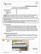
Unscrew screws from the rear of
the chassis then remove the top
cover
Ослабьте два винта на задней
панели корпуса и снимите
верхнюю крышку.
取下上蓋螺絲,取下上蓋板Lösen Sie die beiden Schrauben von
der Rückseite des Gehäuses,
entfernen Sie dann die obere
Abdeckung.
Dévissez les deux vis de l'arrière du
boîtier puis retirez le panneau
supérieur.
Afloje dos tornillos de la parte posterior
del chasis para retirar la cubierta
superior.
Allentare le due viti sul lato posterior
del telaio e poi rimuovere il coperchio
superiore.
取下上盖螺丝,取下上盖板
ケース後部のネジ2本をゆるめ
てからトップカバーを取り
外します。
섀시 후면에 있는 두 개의
나사를 푼 다음
상단 커버를 분리합니다.
Unscrew four screws from the
optical drive bracket to remove it
Lösen Sie die vier Schrauben,
welche den Schacht für das optische
Laufwerk halten, nehmen Sie den
Schacht heraus.
Dévissez les quatre vis fixant le casier
du lecteur optique afin de le retirer
Desatornille cuatro tornillos que
sujetan el bracket del dispositivo óptico
y luego retírelo.
Svitare le 4 viti che tengono la staffa
del drive ottico e quindi rimuoverlo.
Открутите четыре шурупа,
удерживающих кронштейн
жесткого диска, и выньте
кронштейн.
鬆開光碟架4顆螺絲,卸下光碟架
松开光盘架4颗螺丝,卸下光盘架
Before you begin, please make sure that you
(1) have all components collected
(2) check that all components do not have compatibility problems with each other or
with the case
(3) if possible, assemble the components outside the case first to make sure they are working
(4) keep the motherboard manual ready for reference during installation
(5) prepare a Philips screwdriver.

Installation Guide
4
Unscrew two screws from the center brace to remove it
Lesen Sie die beiden Schrauben an der mittleren Halterung, nehmen Sie die Halterung heraus.
Dévissez les deux vis de la barre centrale afin de la retirer.
Desatornille dos tornillos del eje central para quitarlo.
Svitare le due viti del gancio centrale per rimuoverlo.
Открутите два шурупа на центральной скобе и выньте ее.
鬆開中支架2顆螺絲,卸下中支架
松开中支架2颗螺丝,卸下中支架
3

Installation Guide
5
4
Install power supply into the case. If you use a power supply with 120mm fan or bigger, we recommend installing it with the fan facing left (outwards).
If the power supply itself is over 160mm or more in depth, you may need to remove the left case fan first before installation.
For more information regarding power supply size limitations, please refer to the component guide in later pages
Falls Sie ein Netzteil mit einem 120 mm-Lüfter (oder größer) verwenden, empfehlen wir eine Installation, bei der der Lüfter nach links (außen) zeigt.
Falls das Netzteil selbst eine Tiefe von 160 mm oder mehr aufweist, müssen Sie den linken Gehäuselüfter möglicherweise vor der Installation entfernen.
Weitere Hinweise zur Größenbeschränkung bei Netzteilen finden Sie in den Komponentenhinweisen auf den folgenden Seiten.
Si vous utilisez une source d'alimentation avec un ventilateur de 120mm ou plus, nous vous recommandons d'installer avec le ventilateur tourné vers la gauche
(vers l'extérieur).
Si l'alimentation elle-même est plus de 160mm en profondeur, vous aurez besoin de retirer d'abord le ventilateur du boîtier à gauche avant l'installation.
Pour plus de détails sur la limitation de la source d’alimentation, veuillez consulter les guides dans les pages suivantes.
Si usa una fuente de alimentación con un ventilador de 120mm o mayor, le recomendamos instalarlo con el ventilador hacia la izquierda (hacia afuera).
Si la fuente de alimentación en sí tiene 160mm de profundidad o más, podría necesitar retirar primero el ventilador izquierdo de la carcasa antes de la instalación.
Para tener mas informacion sobre las limitaciones de tamano de la fuente de alimentacion, por favor consulte la guia de componenetes que aparece en
paginas posteriores.
Se si utilizza un alimentatore con ventola da 120 mm o più grande, si consiglia di installarlo con la ventola rivolta verso sinistra (verso l'esterno).
Se il cavo d'alimentazione è di per sé supera i 160 mm o più in profondità, potrebbe essere necessario rimuovere la ventola sinistra del case prima dell'installazione.
Per maggiori informazioni in merito alle limitazioni in dimensioni degli alimentatori installabili, fare riferimento alla guida nelle pagine seguenti.
При использовании блока питания со 120-мм и более мощным вентилятором мы рекомендуем устанавливать его, направленным влево (наружу).
Если глубина блока питания превышает 160-мм, перед установкой может потребоваться извлечение вентилятора с левой стороны корпуса.
Более подробную информацию об
ограничениях на габариты блока питания вы найдете на следующих страницах руководства.
將電源供應器由上放入機殼內,如果有12cm或以上尺寸的風扇,我們建議朝左(外部)。如果電源供應器超過160mm深度,可能要先移除左風扇,
待電源供應器安裝好後再鎖回去。關於電源供應器長度規格,請參考元件尺寸限制
将电源供应器由上放入机壳内,如果有12cm或以上尺寸的风扇,我们建议朝左(外部)。如果电源供应器超过160mm深度,可能要先移除左风扇,
待电源供应器安装好后再锁回去。关于电源供应器长度规格,请参考组件尺寸限制
120mmまたはそれより大きいファンの付属した電源を使用される場合は、ファンが左側(外向き)になるように設置することを推奨します。
電源本体が奥行き160mm以上であるならば、インストールの前に最初に左のケースファンを取り外す必要があります。
전원 공급장치에 120mm 이상의 팬이 있는 경우 팬이 정면 왼쪽(바깥쪽)을 향하도록 설치할 것을 권장합니다.
전원 공급장치 자체의 깊이가 160mm 이상일 경우 설치하기 전에 먼저 왼쪽 케이스를 제거해야 합니다.

5
Insert the I/O shield included with your motherboard into the rear I/O slot on the case
Setzen Sie das mit Ihrem Motherboard gelieferte I/O-Blech in die Aussparungen an der Rückseite des Gehäuses ein,
installieren Sie anschließend das Motherboard im Gehäuse.
Insérez la plaque d'E/S inclus avec votre carte mère, puis installez la carte mère dans le boîtier
Inserte el protector de E/S incluido en su placa base, luego instale la placa base en la carcasa.
Installare la mascherina I/O inclusa con la scheda madre, quindi installare la mainboard nel case.
Установите заглушку для разъёмов задней панели материнской платы, прилагаемую к материнской плате,
затем установите материнскую плату в корпус.
將I/O彈片裝上機殼
将I/O弹片装上机壳
お持ちのマザーボードに付属のI/Oシールドを挿入してから、ケースの中にマザーボードを取り付けます。
메인보드와 같이 동봉된 I/O Shield 를삽입한 후, 메인보드를케이스에설치합니다.
Installation Guide
6

Installation Guide
7
6
7
If required, install additional
motherboard standoffs onto the
motherboard tray, then install the
motherboard into the case and secure
with SCREW C
Si nécessaire, veuillez installer des
entretoises de carte mère
supplémentaires sur le plateau de la
carte mère, puis installer la carte mère
dans le boîtier et attachez-la avec la
VIS C.
Si es necesario, instale soportes
adicionales para placas base en la
bandeja de la placa base, luego
instale la placa base en la carcasa y
fíjela con TORNILLOS C
Se necessario, installare distanziatori
supplementari della scheda madre
cassetto della scheda madre, quindi
installare la scheda madre nel case e
fissarla con la VITE C
If required, install additional
motherboard standoffs onto the
motherboard tray, then install the
motherboard into the case and secure
with SCREW C
При необходимости установите
дополнительные опорные винты
на лоток системной платы, затем
установите системную плату в корпус
и закрепите с помощью винта C
请依需求将SCREW D 的主板螺柱锁固
于机壳,再将主板装入机壳,
用SCREW C 螺丝将其锁固
必要な場合は、マザーボードトレイに
追加のマザーボードスペーサーを取り
付けてから、ネジCでマザーボードをケ
ースに固定します。
필요할 경우 메인보드 트레이 위에
메인보드 스탠드오프를 추가 설치한 다음
메인보드를 케이스에 끼우고 나사 C로
고정하십시오.
請依需求將SCREW D 的主機板螺柱鎖
固於機殼,再將主機板裝入機殼,
用SCREW C 螺絲將其鎖固
We recommend at this point to start
thinking about routing the cables
cleanly before connecting them to
the motherboard, cables include fan
cables, power supply 24pin cable,
CPU ATX 4pin/EPS12V 8pin, front
panel connectors, and front I/O
connectors
An diesem Punkt empfehlen wir Ihnen,
über eine saubere Verlegung der Kabel
nachzudenken, bevor Sie die Kabel an
das Motherboard anschließen. Zu den
Kabeln zählen Stromversorgungskabel
(24-polig), CPU ATX-Kabel
(4-polig)/EPS 12 V-Kabel (8-polig),
Frontblenden-Anschlusskabel sowie
Front-I/O-Kabel.
A ce stade nous recommandons de
commencer à organiser proprement
les câbles avant de les brancher à la
carte mère, câbles de ventilateurs,
connecteur 24pin de l'alimentation,
Connecteur ATX 4 pin/EPS12V 8pin
du processeur, connecteurs du
panneau frontal, et les connecteurs
des ports E/S frontaux.
Le recomendamos que en este punto
comience a enrutar los cables con
limpieza antes de conectarlos a la placa
base. El término “cables” incluye los
cables de los ventiladores, el cable de
24 pines de la fuente de alimentación,
el de 4 pines CPU ATX/8 pines EPS12V,
conectores del panel frontal y
conectores de E/S frontales.
A questo punto, si raccomanda di
pensare a come gestire la disposizione
dei cavi interni prima di connetterli alla
scheda madre. Si fa riferimento ai i cavi
delle ventole, all cavo dell’alimentatore
a 24 pin, al 4pin ATX ed EPS 12V 8 pin,
alle connessioni del pannello frontale
ed alle connessioni frontali I/O.
Мы рекомендуем задуматься о
прокладке кабелей до их подключения
к материнской плате. Имеются в
виду
следующие кабели: кабели
вентиляторов, 24-контактный силовой
кабель, 4-контактный ATX и
8-контактный EPS 12В кабели ЦП,
разъемы передней панели и передние
разъемы ввода/вывода.
我們建議您可以在這時開始理線,
請先安插好ATX24Pin接線,
Front panel controller
與Front I/O
我们建议您可以在这时开始理线,
请先安插好ATX24Pin接线,
Front panel controller
与Front I/O
24
CPU ATX 4 /EPS12V 8
I/O
이번 단계에서부터 케이블 정리에대해
생각해주시기를권장합니다.팬케이블,
파워 서플라이 24핀케이블, CPU,
ATX 4핀/EPS 12V 8pin,전면패널 커넥터,
전면 IO 커넥터등이 대상이 됩니다.
d
K
(2
(4
F
F
A
c
le
c
c
C
d
p
d
L
c

Installation Guide
9
9
10
Use small bracket included in the
accessories box to install 3.5” drive
beneath the optical drive area
Verwenden Sie die mitgelieferte
kleine Halterung zur Installation des
3,5-Zoll-Laufwerks unter dem Bereich
des optischen Laufwerks
Utiliser le petit support fourni dans la
boîte d'accessoires pour installer le
disque 3,5" sous la zone de lecteur
optique.
Use el bracket pequeño incluido en
la caja de accesorios para instalar el
dispositivo de 3,5” bajo la zona del
dispositivo óptico
Utilizzare la piccola staffa inclusa nella
scatola degli accessori per installare
l’unità da 3,5" sotto la zona dell’unità
ottica
Для установки 3,5-дюймового диска
под оптическим приводом используйте
малый кронштейн из пакета
аксессуаров
使用零件包內附小架,
安裝光碟機下方的3.5”硬碟
使用零件包内附小架,
安装光驱下方的3.5”硬盘
3.5”ドライブは、アクセサリボックス
内の小型ブラケットを使って、
光学ドライブの下方に設置します。
액세서리 상자에 들어 있는 소형 브래킷을
이용해서 광 드라이브 영역 아래쪽에
3.5" 드라이브를 설치하십시오.
Depending on your configuration,
pre-connect any SATA cables to
your motherboard before installing
expansion cards
Je nach Konfiguration schließen
Sie jegliche SATA-Kabel an Ihrem
Motherboard an, bevor Sie
Erweiterungskarten installieren
Selon votre configuration,
veuillez pré-brancher les câbles
SATA de votre carte mère avant
d'installer des cartes d'extension.
Dependiendo de su configuración,
pre-conecte cualquier cable SATA
a su placa base antes de instalar
las tarjetas de expansión
In base alla configurazione,
pre-collegare tutti i cavi SATA alla
scheda madre prima di installare le
schede di espansione
В зависимости от конфигурации,
перед установкой карт расширения
подключите к системной плате
кабели SATA
視配置而定,介面卡可能擋住主機板
的SATA插槽,建議您先數好需要的
SATA線材,這時先插好
视配置而定,适配卡可能挡住主板
的SATA插槽,建议您先数好需要的
SATA线材,这时先插好
ご使用の構成に依存しますが、
拡張カード装着の前に必要な
SATAケーブルを前もってマザーボー
ドに接続しておきます。
사용자의 구성에 따라서는 확장 카드를
설치하기 전에 메인보드에 SATA
케이블을 미리 연결해야 합니다.

Installation Guide
10
11
Remove expansion slot covers as required, install expansion cards and secure with screws
Entfernen Sie die Abdeckungen des Erweiterungssteckplatzes wie erforderlich; installieren
Sie die Erweiterungskarten und sichern Sie mit Schrauben
Retirez les caches des fentes d’extension si nécessaire, installez les cartes d'extension et attachez-les avec des vis.
Retire las cubiertas de los zócalos de expansión según lo necesite, instale tarjetas de expansión y fíjelas con tornillos
Rimuovere le coperture degli alloggi di espansione come necessario, installare schede di espansione e fissarle con le viti
При необходимости снимите крышки слотов расширения, установите карты расширения и закрепите винтами
先取下擴充槽上的蓋板與擋片,再將擴充卡裝入,並以內附螺絲鎖固。
先取下扩展槽上的盖板与挡片,再将扩充卡装入,并以内附螺丝锁固。
必要に応じて拡張スロットカバーを外し、拡張カードを装着してからネジで固定します。
확장 슬롯 커버를 분리한 다음, 필요한 확장 카드를 설치하고 제공된 나사를 사용하여 고정시키십시오.

Installation Guide
11
Install hard drive and optical drive to optical drive bracket as required. For more details on installation of this bracket, please refer to the
guides in the later pages
Installieren Sie Festplatte und optisches Laufwerk wie erforderlich in der Halterung für optische Laufwerke. Weitere Einzelheiten zur
Installation dieser Halterung entnehmen Sie bitte den Anleitungen auf späteren Seiten
Installez le disque dur et le lecteur optique sur le support de lecteur optique si nécessaire. Pour plus de détails sur l'installation de ce support,
veuillez consulter les guides dans les pages suivantes.
Instale un disco duro o dispositivo óptico en el bracket para dispositivo óptico según lo precise. Para más detalles sobre la instalación
de este bracket, por favor consulte las guías de páginas posteriores
Installare il disco rigido e l’unità ottica al supporto dell'unità ottica come necessario. Per altri dettagli sull'installazione di questa staffa,
di consultare le guide nelle pagine successive
Установите жесткий диск и оптический привод соответствующим образом на кронштейн оптического привода. Подробная информация
по установке этого кронштейна дана в руководствах, приведенных далее
將硬碟與光碟安裝上光碟架,如果要用向下相容的方式安裝,請參考說明
将硬盘与光盘安装上光盘架,如果要用向下兼容的方式安装,请参考说明
必要に応じて、光学ドライブ・ブラケットにハードディスクドライブと光学ドライブをインストールします。
このブラケットのインストールに関する詳細は、後述ページにおけるガイドをご参照ください。
필요할 경우 하드 드라이브와 광 드라이브를 광 드라이브 브래킷에 설치하십시오. 이 브래킷 설치에 관한 자세한 내용은
다음 페이지의 지시사항을 참조하십시오.
12

Installation Guide
12
13
14
Remove 5.25” drive bay cover
if needed
Entfernen Sie die Abdeckung des
5,25-Zoll-Laufwerkseinschubs,
falls erforderlich
Retirez le couvercle de la
baie de lecteur 5,25" si
nécessaire.
Retire la cubierta de la bahía de
dispositivos de 5,25” si lo necesita
Rimuovere la copertura
dell’alloggio unità 5,25",
se necessario
При необходимости снимите
крышку отсека 5,25-дюймового
диска
移除需要安裝的5.25”檔板
移除需要安装的5.25”檔板
必要ならば5.25”ドライブ
ベイカバーを取外します。
필요할 경우 5.25" 드라이브
베이 커버를 벗기십시오.
Bauen Sie die mittlere Halterung
wieder in das Gehäuse ein.
Réinstallez la barre central
dans le boîtier.
Reinstale el eje central
en la carcasa.
Reinstallare il gancio centrale
nel case.
Вставьте центральную скобу
обратно в корпус.
安裝中支架
安装中支架
Reinstall the center brace back
into the case

Installation Guide
13
15
16
Reinstall the optical drive bracket
back into the case
Installieren Sie die Halterung für
optische Halterungen wieder im
Gehäuse
Réinstallez le support du lecteur
optique dans le boîtier.
Reinstale el bracket para
dispositivo óptico de nuevo en
la carcasa
Reinstallare il supporto dell'unità
ottica sul telaio
Установите кронштейн оптического
привода в корпус
將光碟架裝回機殼
将光盘架装回机壳
光学ドライブ・ブラケッ
トをケースに戻します。
광 브라이브 브래킷을 케이스에
도로 끼우십시오.
Schließen Sie alle Daten- und
Netzkabel für die installierten
Laufwerke an. 90 Grad abgewinkelte
Anschlüsse eignen sich zum besseren
Platzsparen
Branchez tous les câbles de données
et d'alimentation pour les lecteurs
installés. Des connecteurs coudés
à 90 degrés sont recommandés pour
mieux économiser de l'espace.
Conecte todos los cables de datos
y potencia para los dispositivos
instalados. Los conectores en ángulo
de 90 grados se recomiendan para
ahorrar más espacio
Collegare tutti i cavi dati e di
alimentazione per le unità installate.
Sono raccomandati connettori ad
angolo di 90 gradi per un migliore
risparmio di spazio
Подключите все кабели данных и
питания к установленным приводам.
Для оптимального использования
объема корпуса рекомендуется
использовать Г-образные разъемы
安裝所有Drive Bay的連接線,
無論是排線或是電源線,我們都建議
最好用90度的,比較省空間
安装所有Drive Bay的连接线,
无论是扁平电缆或是电源线,我们都建
议最好用90度的,比较省空间
装着されたドライブの用のデータ
および電源ケーブルを全部接続します。
より優れたスペース節約には、90度ア
ングルコネクタがお勧めです。
설치된 드라이브를 위한 모든 데이터와
전원 케이블을 연결하십시오. 좁은
공간의 경우 90도 각도의 커넥터
사용을 권장합니다.
Connect all data and power cables
for installed drives. 90 degree
angled connectors are recommended
for better space saving
Sc
Ne
La
An
Pla
Bra
et d
in
s
à 9
mi
e
Co

Installation Guide
14
17
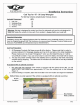
Reinstall top cover back onto the case to complete installation
Bringen Sie zum Abschluss der Installation die obere Abdeckung wieder am Gehäuse an
Réinstallez le couvercle supérieur sur le boîtier pour terminer l'installation.
Reinstale la cubierta superior de nuevo en la carcasa para completar la instalación
Reinstallare la copertura superiore sul case per completare l'installazione
Установите верхнюю крышку на корпус
裝回上蓋板,完成組裝
装回上盖板,完成组装
上部カバーをケースに戻すと、インストールは完了です。
상단 커버를 케이스에 도로 씌우면 설치가 완료됩니다.

15
Connector definition
(1) Front panel connector installation no polarity, so they can be connected
in any orientation
Power switch and reset switch installation guide:
Please refer to the motherboard manuals for the motherboard’s “Front Panel Connector” or “System Panel Connector” pin definitio
Power switch and reset switch have no polarity, so they can be connected in any orientation.
Bitte suchen Sie in der Motherboard-Dokumentation nach der Pinbelegung der Anschlüsse des Frontbedienfeldes („Front Panel Conne
oder „ System Panel Connectors“). Ein-/Austaste und Rücksetztaste benötigen keine bestimmte Polarität, können daher beliebig (o
und - zu achten) angeschlossen werden.
Veuillez-vous référer au manuel de votre carte mère pour la description des broches "des connecteurs du panneau frontal" et des
"des connecteurs du panneau système". Les interrupteurs d'allumage et de réinitialisation ne possède pas de polarité, donc ils peuvent être
branché dans les deux sens.
Por favor, consulte en los manuales de la placa base la configuración de pines del “Conector de panel frontal” ó “Conector de panel de sistema”
de su placa base. Los interruptores de encendido y reseteo no tienen polaridad, luego se pueden conectar con cualquier orientac
Fare riferimento al manuale della scheda madre nella sezione “Connettori del pannello frontale” o “Connettori del pannello di sistema”. Power
switch e reset switch non hanno polarità, posso essere pertanto connessi con qualsiasi orientamento.
Описание контактов разъемов приведены в разделах “Разъемы передней панели” или “Разъемы системной панели” руководства
пользователя материнской платы. Выключатель питания и кнопка перезагрузки не имеют полярности, поэтому их можно подключать
в любой ориентации.
請參考主機說明書的Front Panel Connectors安裝Pin Define,將Connector插上;Power Switch 與Reset Switch並無正負極性之分,
反插正插都不影響功能性。
请参考主机说明书的Front Panel Connectors安装Pin Define,将Connector插上;Power Switch 与Reset Switch并无正负极性之分,
反插正插都不影响功能性。
메인보드 매뉴얼의 전면패널 커넥터 혹은 시스템패널 커넥터 핀을 참조하기 바랍니다. 파워 스위치와 리셋 스위치는 극성이 없어 어떤
방향으로 설치해도 무방합니다.
マザーボードの「フロントパネルコネクタ」または「システムパネルコネクタ」のピン配列についてはマザーボードマニュアルを参照してください。
電源スイッチとリセットスイッチに極性はないので、いずれの方向でも接続できま。

Connector definition
16
Please refer to the motherboard manuals for the motherboard’s “Front Panel Connector ” or “System Panel Connector” pin definition.; the white/black
wires are negative while other colors are positive wires. The Power LED wires are separate pins for compatibility with different motherboard pin
definition so please make sure they are connected in the right polarity by referring to your motherboard manual.
Bitte suchen Sie in der Motherboard-Dokumentation nach der Pinbelegung der Anschlüsse des Frontbedienfeldes („Front Panel Connectors“ oder „
System Panel Connectors“). Die weißen/ schwarz Adern sind negativ (-), die farbigen Adern positiv (+).Die Kabel für die Betriebsanzeige-LED sind
zur Kompatibilität mit unterschiedlichsten Motherboards einzeln, nicht als kompletter Stecker ausgeführt. Achten Sie hier bitte auf die richtige
Polarität, lesen Sie in der Dokumentation Ihres Motherboards nach.
Veuillez-vous référer au manuel de votre carte mère pour la description des broches "des connecteurs du panneau frontal" et des broches "des connecteurs du panneau
système". Les câbles colorés en blanc/noir sont négatifs alors que ceux d'une autre couleur sont positifs. Les câbles de la LED Power sont séparés afin d'être compatible
avec différentes cartes mères, donc vérifiez bien qu'ils sont branchés avec la bonne polarité en vous référant au manuel de votre carte mère
Por favor, consulte en los manuales de la placa base la configuración de pines del “Conector de panel frontal” ó “Conector de panel de sistema” de
su placa base. Los cables de color blanco/negro son negativos mientras que los de color son positivos. Los cables LED de potencia tienen pines
separados para compatibilidad con diferentes definiciones de pines de la placa base luego por favor, asegúrese de que están conectados en la
polaridad correcta consultando el manual de su placa base.
Fare riferimento al manuale della scheda madre nella sezione “Connettori del pannello frontale” o “Connettori del pannello di sistema”. I cavi di
colore bianco/nero sono il polo negativo, mentre quelli di colore diverso il positivo.
Описание контактов разъемов приведены в разделах “Разъемы передней панели” или “Разъемы системной панели” руководства
пользователя материнской платы. Белые/черный провода - отрицательной полярности, цветные провода - положительной полярности.
Провода светодиодного индикатора питания имеют отдельные контакты для совместимости с различными типами контактов материнских
плат, поэтому обратитесь к руководству пользователя материнской платы и убедитесь, что
полярность соблюдена.
請參考主機說明書的Front Panel Connectors安裝Pin Define,將Connector插上; 白/黑色線的部分為負極,彩色線的部分是正極。
Power LED為了適應各主機板的不同, 特別設計為散Pin樣式,請安心使用。
请参考说明书的Front Panel Connectors安装Pin Define,将Connector插上;白/黑色线的部份为负极,彩色线的部份为正极。
Power LED为了适应主机板的不同, 特别设计为散Pin样式,请安心使用。
메인보드 매뉴얼의 전면패널 커넥터 혹은 시스템패널 커넥터 핀을 참조하기 바랍니다. 하얀/검은선의 경우 음극이며, 다른 색의 경우
양극입니다. 파워 LED 선은 분리되어 다양한 메인보드에서 동작할 수 있도록 되어 있습니다. 그러므로 메인보드 매뉴얼을 참조하여 올바를
극성을 주의해 선택하시기 바랍니다.
マザーボードの「フロントパネルコネクタ」または「システムパネルコネクタ」ピン配列についてはマザーボードマニュアルを参照してください。
白/黑色のリード線はマイナスで、色の着いたリード線がプラスです。電源LEDリード線は種々のマザーボードピン定義と互換性を持たせるため分離されたピ
ンとなっているので、ご使用のマザーボードマニュアルを参照して、適切な極性に接続されるようお確かめください。
(2) LED indicators installation guide

Connector definition
17
Below are the front I/O connectors pin definition, please also check your motherboard manual to cross reference with motherboard’s
front I/O pin headers. SilverStone’s I/O connectors are in block type to simplify installation.
Nachstehend finden Sie die Pinbelegung der vorderen E/A-Anschlüsse; bitte gleichen Sie zudem das Handbuch Ihres Motherboards mit
den vorderen E/A-Pinzuweisungen ab. SilverStones E/A-Anschlüsse befinden sich zur Vereinfachung der Installation in Blockart.
Au dessous de la description des broches des ports d'E/S, veuillez aussi vérifier sur le manuel de votre carte mère de manière croisée
que les broches sont correctement placées. Les connecteurs d'E/S de SilverStone sont en bloc pour en simplifier leur installation.
A continuación tiene la definición de pines de los conectores frontales de E/S, también debe consultar el manual de su placa base para c
omprobar la referencia de los pines para E/S frontales. Los conectores de E/S de SilverStone son de bloque para simplificar la instalación.
Di seguito lo schema delle connessioni I/O frontali, confrontare lo schema con quanto riportato sul manuale della scheda madre per
effettuare una controllo incrociato. I connettori I/O Silverstone, per semplificare l’installazione, sono del tipo “a blocco”.
Ниже приведено описание контактов передних разъемов ввода/вывода. Обратитесь также к руководству пользователя материнской
платы за описанием передних разъемов ввода/вывода типа "пин-хедер". Разъемы ввода/вывода "SilverStone" - блочного типа, что
облегчает сборку.
下表為Front I/O Connectors的Pin Define,請參閱主機板說明書的各Front I/O Connectors Pin Define一一核對。
Front I/O Connectors完全採用集合Pin方式以簡化安裝。
下表为Front I/O Connectors的Pin Define,请参阅主机板说明书的各Front I/O Connectors Pin Define一一核对。
Front I/O Connectors完全采用集合Pin方式以简化安装。
아래는 전면 I/O 커넥터의 핀 설정이며, 메인보드 매뉴얼을 참조해 메인보드의 전면 I/O 핀 헤더와 맞추어 설치합니다.
Silverstone의 I/O 커낵터는 블록 타이브로 구성되어 설치를 간편화 했습니다.
以下はフロントI/Oコネクタピン配列ですが、お持ちのマザーボードのフロントI/Oピンヘッダは、マザーボードマニュアルをご参照ください。
シルバーストーンのI/Oコネクタは、インストールの容易なブロックタイプになっています。
(3) Front I/O connector guide
HD AUDIO CONNECTOR
VBUS
PORT1L
PORT1R
PORT2R
SENSE_SEND
PORT2L
PIN
AUD GND
PRESENCE
SENSE1_RETURN
PIN
SENSE2_RETURN
INTA_P2_SSRX-
INTA_P2_SSRX+
INTA_P2_SSTX-
INTA_P2_SSTX+
INTA_P2_D-
INTA_P2_D+
GND
GND
VBUS
INTA_P2_SSRX-
INTA_P2_SSRX+
INTA_P2_SSTX-
INTA_P2_SSTX+
INTA_P1_D-
INTA_P1_D+
ID
PIN 10
PIN 1
PIN 19
PIN 11
GND
GND
USB3.0 CONNECTOR

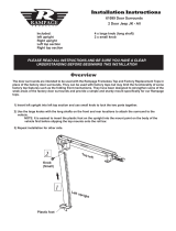
Component size limitations
A: Illustration: ASUS Rampage III Extreme is wider than standard ATX size of 9.6 inches
Although GD10 does not support true Extended ATX (SSI-EEB) motherboards, it does support ATX models up to 11 inches wide.
Motherboard standoff holes are included to support SSI-CEB so high-end enthusiasts ATX boards such as ASUS Rampage III Extreme
or EVGA X58 SLI Classified, which are up to 10.6 inches wide, can fit comfortably inside GD10.
B: Illustration: New generation of SSI-CEB server or workstation motherboards no longer require CPU cooler mounting holes on the
motherboard tray.
Coolers can now be installed directly on the motherboard. As a result, we eliminated support for SSI-CEB CPU cooler mounting holes and
instead increased the large gap on the motherboard tray to support CPU cooler back plates swapping with more LGA 115X motherboards.
The GD10 chassis’ support for new and future SSI-CEB motherboards should be unaffected by this change.
A: Abbildung: Das ASUS Rampage II Extreme ist breiter als die Standard-ATX-Größe von 9,6 Zoll
Obwohl das GD10 keine echten Extended ATX- (SSI-EEB) Motherboards unterstützt, unterstützt es ATX-Modelle mit einer Breite bis 11-Zoll.
Löcher für Motherboard-Abstandhalter sind zur Unterstützung von SSI-CEB verfügbar, sodass High-End-Enthusiasten ATX-Platinen, wie ASUS
Rampage III Extreme oder EVGA X58 SLI Classified, die bis zu 10,6-Zoll breit sind, komfortabel im GD10 unterbringen können.
B: Abbildung: Hochmoderne Motherboards von SSI-CEB-Servern und -Arbeitsrechnern benötigen keine Löcher zur CPU-Kühlermontage
am Motherboard-Einschub mehr.
Die Kühler können nun direkt am Motherboard installiert werden. Dadurch haben wir die Unterstützung der Löcher zur
SSI-CEB-CPU-Kühlermontage aufgegeben und stattdessen den Abstand am Motherboard-Einschub vergrößert; dadurch werden
CPU-Kühlerrückplatten unterstützt, die mit einer größeren Anzahl an LGA 115X-Motherboards kompatibel sind. Die Unterstützung neuer und
zukünftiger SSI-CEB-Motherboards durch das GD10-Gehäuse wird durch diese Änderung nicht beeinflusst.
A: Illustration : ASUS Rampage III Extreme est plus large que la taille ATX standard de 9,6 pouces
Bien que le GD10 ne supporte pas les cartes mères Extended ATX (SSI-EEB), il supporte les modèles ATX jusqu'à 11 pouces de large. Des
trous pour les espaceurs de carte mère sont inclus pour supporter SSI-CEB pour que les cartes ATX de haut de gamme tels que ASUS Rampage
III Extreme ou EVGA X58 SLI Classified, qui ont une largeur de jusqu'à 10,6", puissent rentrer facilement à l'intérieur du GD10.
B: Illustration : Les portes-carte mère destinés à la nouvelle génération de cartes mères pour station de travail ou serveur SSI-CEB n'ont plus besoin
de trous de montage pour le refroidisseur de l'unité centrale. Les refroidisseurs peuvent désormais s'installer directement sur la carte mère.
Nous avons ainsi éliminé le support destiné aux trous de montage pour le refroidisseur de l'unité centrale SSI-CEB et l'espace sur le porte-carte
mère permettant de permuter les plaques arrière du refroidisseur, avec plus de cartes mères LGA 115X, est agrandi. Le support du châssis GD10
pour les nouvelles cartes mères SSI-CEB et celles à venir, ne sera pas affecté par cette modification.
A: Ilustración: la ASUS Rampage III Extreme es más ancha que el tamaño estándar ATX de 9,6 pulgadas
Aunque la GD10 no acepta verdaderas placas base ATX Extendidas (SSI-EEB), acepta modelos ATX de hasta 11 pulgadas de ancho. Los agujeros
para soportes de la placa base se incluyen para aceptar SSI-CEB, luego los entusiastas de placas ATX de alto rendimiento como la ASUS
Rampage III Extreme o la EVGA X58 SLI Classified, que tienen hasta 10,6 pulgadas de ancho, puedan encajar cómodamente dentro de la GD10.
B: Ilustración: La nueva generación de placas base de servidor o estaciones de trabajo SSI-CEB ya no necesita agujeros de montaje para disipador
de CPU en la bandeja de la placa base.
Los disipadores ahora se pueden instalar directamente en la placa base. Como resultado, eliminamos los agujeros de montaje de disipador para
CPU SSI-CEB y en cambio aumentamos el gran espacio en la bandeja de la placa base para aceptar el cambio de placas traseras para disipador
de CPU con más placas base LGA 115X. Que el chasis de la GD10 acepte placas base SSI-CEB nuevas y futuras no debería verse afectado por
este cambio.
A: Illustrazione: ASUS Rampage III Extreme è più larga delle ATX standard da 9,6 pollici
Anche se GD10 non supporta schede madre true Extended ATX (SSI-EEB), supporta modelli ATX larghi fino a 11 pollici. Sono inclusi fori per
distanziatori della scheda madre per supportare SSI-CEB così che schede ATX high-end per appassionati come ASUS Rampage III Extreme o
EVGA X58 SLI Classified, che sono larghe fino a 10.6 pollici, possono stare comodamente dentro a GD10.
B: Illustrazione: Nuove generazioni di schede madre per server SSI-CEB o per workstation non richiedono più fori di montaggio per dispersori di
calore CPU sul cassetto della scheda madre.
I dispersori di calore possono essere installati direttamente sulla scheda madre. Di conseguenza abbiamo eliminato il supporto per fori di
montaggio per il dispersore di calore SSI-CEB, ed invece abbiamo aumentato l’ampio spazio libero sul cassetto della scheda madre per
supportare scambiatori di calore CPU con più schede madri LGA 115X. Il supporto del telaio di GD10 per le nuove e future schede madre
SSI-CEB non dovrebbe essere influenzato da questo cambiamento.
(4) Motherboard width limitation
(A) (B)
23

Recommended cooling device setup and selection
SilverStone provides a selection of retail 120mm fans for upgrade or replacement
*FQ121, 120mm, 1000 ~ 1800rpm *AP122, 120mm, 1200rpm
Hard drive and CPU
Graphics cards
Assist in exhausting air
Right side fan, front
Left side fan
Right side fan, rear CPU and components around CPU socket
Rear fan
27
Per impostazione predefinita, GD10 comprende 3 ventole che soddisfano quasi tutte le esigenze di raffreddamento Se si vogliono sostituire o
aggiungere altre ventole, si consiglia di installarle come ventole di aspirazione nei restanti alloggi ventola, fatta eccezione per la parte posteriore.
Di seguito la posizione delle ventole in relazione ai componenti che raffreddano:
Par défaut, votre GD10 comprend 3 ventilateurs permettant de répondre à presque tous les besoins de refroidissement.
Si vous souhaitez remplacer ou ajouter plus de ventilateurs, nous vous recommandons de les installer comme des ventilateurs d'entrée
d'air, dans les fentes de ventilation restantes sauf à l'arrière.
Les illustrations suivantes vous indiquent l’emplacement des ventilateurs en fonction des composants qu’ils doivent refroidir :
Por defecto, la GD10 incluye 3 ventiladores para casi cualquier necesidad de refrigeración. Si desea reemplazar o añadir más ventiladores,
le recomendamos instalarlos como ventiladores de entrada en los zócalos para ventilador restantes, excepto el trasero.
A continuación están las posiciones de los ventiladores en relación a los componentes que refrigeran:
По умолчанию GD10 включает 3 вентилятора, которые обеспечивают практически все требования к охлаждению.
Если вы хотите заменить или установить дополнительные вентиляторы, мы рекомендуем устанавливать их в качестве нагнетательных
в свободных слотах вентиляторов, за исключением заднего.
Ниже показано расположение вентиляторов относительно компонентов, которые они охлаждают:
기본적으로 GD10에는 거의 모든 냉각 요구조건에 맞는 3대의 팬이 포함되어 있습니다. 보다 많은 수의 팬을 교체하거나 추가하려는 경우
뒷면을 제외한 나머지 팬 슬롯에 흡기 팬으로 설치하는 것이 좋습니다.
다음은 냉각 기능을 제공하는 구성품과 관련된 팬 위치입니다:
GD10已經配有3顆風扇,以對應絕大部分散熱需求
如果有需要添購風扇,我們建議您可以在其餘風扇位置安裝進氣風扇
下表為進氣風扇對應的元件散熱的針對性
GD10已经配有3颗风扇,以对应绝大部分散热需求
如果有需要添购风扇,我们建议您可以在其余风扇位置安装进气风扇
下表为进气风扇对应的组件散热的针对性
デフォルトでは、GD10はほとんど全ての冷却要件に適う3台のファンが含まれます。より多くのファンを設置するか、交換される場合、
後部以外はファンスロットに吸気ファンとして設置されるようお勧めします。
下記は、冷却の対象となるコンポーネントに関するファン位置です:
By default, GD10 includes 3 fans to nearly all cooling requirements. If you like to replace or add more fans, we recommend installing
them as intake fans in the remaining fan slots except the rear.
Below are fan positions in relation to the components they provide cooling for:
Standardmäßig verfügt das GD10 über 3 Lüfter zur Erfüllung nahezu aller Kühlanforderungen. Falls Sie Lüfter ersetzen oder weitere
Lüfter hinzufügen möchten, sollten Sie diese als Zuluftlüfter in den verbleibenden Lüftersteckplätze (außer an der Rückseite) installieren.
Lüfter-Einbauplätzen anzubringen. Nachfolgend sehen Sie, welche Komponenten durch welche Lüfter gekühlt werden:
(3) Recommendation for fan installation
/