1-8 Chapter 1: Product introduction
9. BIOS FlashBackTM button. Press the BIOS FlashBackTM button for three seconds until
the FlashBackTM LED blinks three times, indicating that the BIOS FlashBackTM function
is enabled.
To use BIOS FlashBack™:
1) Insert a USB storage device to the BIOS FlashBack™ port.
2) Visit https://www.asus.com/support/ and download the latest BIOS version for this
motherboard.
3) Manually rename the le as TGB550PW.CAP, or launch the BIOSRenamer.exe
application to automatically rename the le, then copy it to your USB storage device.
The BIOSRenamer.exe application is zipped together with your BIOS le when you
download a BIOS le for a BIOS FlashBack™ compatible motherboard.
4) Shut down your computer.
5) Press the BIOS FlashBack™ button for three (3) seconds until the BIOS FlashBack™
LED blinks three times, indicating that the BIOS FlashBack™ function is enabled.
6) Wait until the light goes out, indicating that the BIOS updating process is completed.
10. USB 3.2 Gen 1 (up to 5Gbps) ports. These 9-pin Universal Serial Bus (USB) ports
connect to USB 3.2 Gen 1 devices.
11. USB 3.2 Gen 2 (up to 10Gbps) port (USB Type-C®). This 9-pin Universal Serial Bus
3.2 (USB 3.2) port is for USB 3.2 Gen 2 Type-C® devices.
12. HDMITM port. This port is for a High-Denition Multimedia Interface (HDMITM)
connector, and is HDCP compliant allowing playback of HD DVD, Blu-ray, and other
protected content.
13. Intel® Wi-Fi 6 AX200 ports. These ports connect to Wi-Fi antennas.
• Ensure that the ASUS 2x2 dual-band Wi-Fi moving antenna is securely installed to the
Wi-Fi ports.
• Ensure that the antenna is at least 20 cm away from all persons.
14. Optical S/PDIF Out port. This port connects to the optical S/PDIF devices.
15. Microphone port (pink). This port connects a microphone.
16. Line Out port (lime). This port connects a headphone or a speaker. In 4-channel,
5.1-channel, and 7.1-channel congurations, the function of this port becomes Front
Speaker Out.
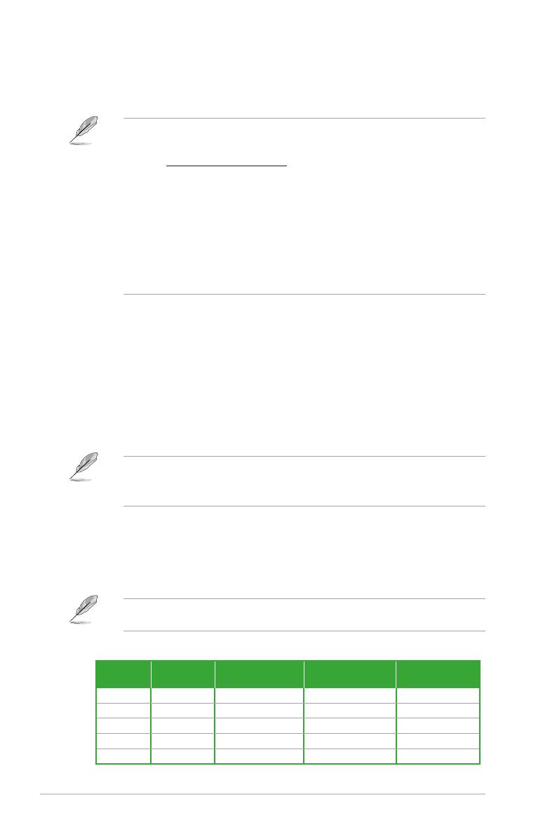
Refer to the audio conguration table for the function of the audio ports in 2, 4, 5.1, or
7.1-channel conguration.
Audio 2, 4, 5.1 or 7.1-channel configuration
Port Headset
2-channel 4-channel 5.1-channel 7.1-channel
Light Blue Line In Line In Line In Side Speaker Out
Lime Line Out Front Speaker Out Front Speaker Out Front Speaker Out
Pink Mic In Mic In Mic In Mic In
Orange – – Center/Subwoofer Center/Subwoofer
Black – Rear Speaker Out Rear Speaker Out Rear Speaker Out