Page is loading ...

1680-2414 Rev. A Made in the U.S.A.
December 2018
User’s Guide
Registered Company
Winona, Minnesota USA
ISO 9001
TOTAL
3 Year Warranty
CUSTOMER
SATISFACTION
F4T Controller
Setup and Operations
1241 Bundy Boulevard., Winona, Minnesota USA 55987
Phone: +1 (507) 454-5300, Fax: +1 (507) 452-4507
http://www.watlow.com/F4T.cfm

Safety Information
We use note, caution and warning symbols throughout this document to draw your attention to
important operational and safety information.
A “NOTE” marks a short message to alert you to an important detail.
A “CAUTION” safety alert appears with information that is important for protecting your
equipment and performance. Be especially careful to read and follow all cautions that
apply to your application.
A “WARNING” safety alert appears with information that is important for protecting you,
others and equipment from damage. Pay very close attention to all warnings that apply to
your application.
The safety alert symbol, (an exclamation point in a triangle
ç
) precedes a general
CAUTION or WARNING statement.
The electrical hazard symbol, (a lightning bolt in a triangle
Ó
) precedes an electric shock
hazard CAUTION or WARNING safety statement. Further explanations follow:
Symbol Explanation
ç
Ó
CAUTION: Warning or Electrical Hazard that needs further explana-
tion than label on unit can provide. Consult QSG for further infor-
mation.
AVERTISSEMENT: mise en garde ou danger qui demande plus de
précisions que l’information sur l’étiquette de l’unité. Consultez le
manuel de l’utilisateur pour plus d’informations.
Unit can be powered with either alternating current (ac) voltage or
direct current (dc) voltage.
ESD Sensitive product, use proper grounding and handling tech-
niques when installing or servicing product.
Do not throw in trash, use proper recycling techniques or consult
manufacturer for proper disposal.
Enclosure made of Polycarbonate material. Use proper recycling
techniques or consult manufacturer for proper disposal.
Unit is a Listed device per Underwriters Laboratories
®
. It has been
evaluated to United States and Canadian requirements for Process
Control Equipment. CSA 22.2#14, File 158031, UL 61010, File
E185611 QUYX, QUYX7. See: www.ul.com
Unit is compliant with European Union directives. See Declaration
of Conformity for further details on Directives and Standards used
for Compliance.
Unit has been reviewed and approved by Factory Mutual as a
Temperature Limit Device per FM Class 3545 standard. See: www.
fmglobal.com
CAUTION
WARNING
Electrical
Shock Hazard
or

Symbol Explanation
Unit has been reviewed and approved by CSA International for use
as Temperature Indicating-Regulating Equipment per CSA C22.2 No.
24. See: www.csa-international.org
This F4T User’s Guide is copyrighted by Watlow Electric Manufacturing Company, © April 2016
with all rights reserved.
• © 2010-2012, QNX Software Systems Limited. All rights reserved.
• © 2008 -2014, Crank Software Inc. All rights reserved.
• Watlow
®
, Composer
®
and TRU-TUNE
®
are registered trademarks of Watlow Electric
Manufacturing Company.
• UL
®
is a registered trademark of Underwriter's Laboratories Incorporated.
• Modbus
®
is a registered trademark of Schneider Automation Incorporated.
• Vaisala
®
is a registered trademark of Vaisala OY Corporation.
• Microsoft
®
and Windows
®
are registered trademarks of the Microsoft Corporation.
Quencharc
®
is a registered trademark of ITW Paktron.
10-31815 Rev.

Watlow F4T Controller • 1 • Table of Contents
TC
Table of Contents .........................................1
Chapter 1: Overview
.......................................4
Available F4T Literature and Resources ....................................4
Technical Assistance
..................................................4
Document Overview and Purpose
........................................5
A Conceptual View of the F4T System
.....................................6
Inputs
............................................................7
Functions
.........................................................7
Outputs
..........................................................8
What is a Profile
...................................................8
Data Logging
......................................................8
Chapter 2: Composer
®
Software ...............................9
Installing Composer
®
Software ..........................................9
Using Composer
®
Software ...........................................10
Overview Screen
...................................................12
Device Details
......................................................17
Configuring Pluggable Flex Modules
.....................................18
Configuring the Application using the Function Block Diagram
................20
Personalizing the User Interface (UI) Using Composer
® ....................... 27
Setting Up Data Log Files Using Composer
® ................................. 27
Creating and Editing Profiles Using Composer
® ..................................35
Chapter 3: Using the F4T Front Panel ...........................43
Navigating and Understanding the User Interface (UI) .......................43
Understanding F4T Menus
...........................................43
Event Driven Menus
................................................43
Home Screen Described
............................................45
Front Panel Navigational Buttons
......................................45
Configuring Ethernet Communications
...................................46
Default Ethernet Parameters and Settings
...............................46
Personalizing the Home Screen Using the UI
..............................47
Front Panel Usage From the Home Screen
................................49
Creating a Profile
..................................................49
Profile Actions From the Home Screen
.................................51
Starting a Profile Using the Calendar
...................................52
Changing Loop Operational Parameters
................................52
Using the Output Widget
............................................53
Table of Contents

Watlow F4T Controller • 2 • Table of Contents
TC
Table of Contents (cont.)
Chapter 3: Using the F4T Front Panel (cont.)
Data Logging .......................................................54
Batch Processing Programming
........................................56
Export Data Log Report - via USB Stick
................................60
Adding "Part-Profile List" using a PC
...................................61
Transferring Data Log Files via the UI
....................................64
Flashing the Controller Firmware
........................................64
Chapter 4: Application Examples ..............................66
Applications ........................................................66
Single Loop Control
................................................66
Heat and Cool Control Loop
..........................................67
Process Alarm
....................................................69
Deviation Alarm
...................................................70
Safety Limit
......................................................72
Sensor Backup
....................................................73
Profile Ramp and Soak
.............................................74
Cascade Control
...................................................75
Compressor Control
................................................77
Chapter 5: Function Block Reference ...........................79
F4T Functions Described ..............................................82
Alarm
............................................................83
Analog Outputs
.....................................................90
Cascade
...........................................................92
Compare
.........................................................107
Control Loop
......................................................112
Counter
..........................................................125
Current Input
......................................................128
Digital Input
.......................................................130
Digital Inputs/Outputs (I/O)
...........................................131
Digital Outputs
.....................................................134
Key
.............................................................137
Limit
............................................................138
Limit Output
......................................................140
Linearization
......................................................140
Logic
............................................................147
Math
............................................................155
Signals
.......................................................157

Watlow F4T Controller • 3 • Table of Contents
Chapter 5: Function Block Reference (cont.)
Profile ...........................................................169
Process Value
.....................................................175
Special Output
.....................................................187
Temperature Input
..................................................192
Thermistor Input
...................................................195
Timer
............................................................197
Universal Input
...................................................204
Variable
..........................................................216
Chapter 6: Appendix .....................................219
Communications ...................................................219
Introduction to Standard Commands for Programmable Instruments (SCPI)
...219
Introduction to the Modbus Protocol
..................................221
Modbus Table Orientation
..........................................223
F4 Modbus Registers Migrated to F4T (Map 2)
..........................309
F4T Base Specifications
..............................................311
F4T Base Ordering Information
......................................314
Flex Modules and Limit I/O Specifications
...............................315
Flex Module - Mixed I/O Ordering Information
..........................319
Flex Module - Limit Ordering Information
..............................320
Flex Modules - High Density I/O Specifications
............................321
Flex Module - High Density Ordering Information
........................324
How to Reach Us
...................................................328
TC
Table of Contents (cont.)

Watlow F4T • 4 • Chapter 1 Overview
Chapter 1: Overview
1
Document Title and Part Number Description
F4T Installation and Troubleshooting
User Guide, part number:
0600-0092-0000
Provides detailed specifications and information
regarding mounting the F4T base, flex module wir-
ing and troubleshooting.
F4T Specification Sheet, part
number: WIN-F4T-1118
Describes F4T hardware options, features, benefits
and technical specifications.
Watlow Application Guide
Comprehensive guide to understanding thermal
principles, electrical noise, best practises for wir-
ing industrial controls and much more.
Watlow Support Tools DVD, part
number: 0601-0001-0000
Contains all product related user documents and
software (Composer™), video tutorials, applica-
tion notes and more.
To acquire one or more of these documents navigate to the Watlow website where you will
have a choice to download free copies or purchase printed versions. Click on the link below to
find your document of choice: http://w ww.watlow.com/literature/index.cfm
Your Comments are Appreciated
In an effort to continually improve our technical literature and ensuring that we are providing
information that is useful to you, we would very much appreciate your comments and sugges-
tions. Please send any comments you may have to the following email address:
TechlitComments@watlow.com
Technical Assistance
If you encounter a problem with your Watlow controller, review your configuration information
to verify that your selections are consistent with your application: inputs, outputs, alarms,
limits, etc. If the problem persists, you can get technical assistance from your local Watlow
representative (see the Appendix in this User's Guide), by e-mailing your questions to wintech-
support@watlow.com or by dialing +1 (507) 494-5656 between 7 a.m. and 5 p.m., Central Stan-
dard Time (CST). Ask for for an Applications Engineer. Please have the following information
available when calling:
• Complete model number • User’s Guide • All configuration information
Warranty
This product is warranted by Watlow for a period of 36 months in accordance with the
terms and conditions set forth on Watlow's website which can be accessed at
www.watlow.com/terms.
Available F4T Literature and Resources

Watlow F4T • 5 • Chapter 1 Overview
Return Material Authorization (RMA)
1. Call Watlow Customer Service, (507) 454-5300, for a Return Material Authorization (RMA)
number before returning any item for repair. If you do not know why the product failed,
contact an Application Engineer or Product Manager. All RMA’s require:
• Ship-to address
• Bill-to address
• Contact name
• Phone number
• Method of return shipment
• Your P.O. number
• Detailed description of the problem
• Any special instructions
• Name and phone number of person returning the product.
2. Prior approval and an RMA number from the Customer Service Department is required
when returning any product. Make sure the RMA number is on the outside of the carton
and on all paperwork returned. Ship on a Freight Prepaid basis.
3. After we receive your return, we will examine it to verify the reason for the product fail-
ure. Unless otherwise agreed to in writing, Watlow's standard warranty provisions, which
can be located at www.watlow.com/terms, will apply to any failed product.
4. In the event that the product is not subject to an applicable warranty, we will quote
repair costs to you and request a purchase order from you prior to proceeding with the
repair work.
5. Watlow reserves the right to charge for no trouble found (NTF) returns.
Document Overview and Purpose
This document looks deeper at the system configuration using Composer™ software and the
F4T function blocks and their associated connections. Common product usage is described and
illustrated through application examples.

Watlow F4T • 6 • Chapter 1 Overview
A Conceptual View of the F4T System
The flexibility of the F4T controller hardware and software (Composer™) allows for a large
range of configurations. Composer software is a graphically based tool used to program the
F4T controller in its entirety. To learn more about installing and using Composer software see
Chapter 2 of this document in the section titled "Installing Composer Software".
Acquiring a better understanding of the controller’s overall functionality and capabilities while
at the same time planning out how the controller can be used will deliver maximum effec-
tiveness in your application.
It is useful to think of the controller in three parts: inputs, functions and outputs. For the
control itself, information flows from an input to a function to an output when the controller
is properly configured. The F4T system can carry out several functions at the same time; such
as, monitoring and acting upon various inputs (temperature sensing devices, pressure trans-
ducers and digital inputs), PID control, monitoring for several different alarm situations and
then driving output devices such as heaters, audible alarms, and lights. Each process needs
to be thought out carefully and the controller’s inputs, functions and outputs set up properly.
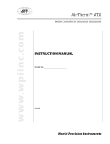
As an example, the graphic below illustrates the Function Block Diagram as seen when using
Composer software. The application requirements in this example are simple and defined be-
low:
• Need two thermocouple inputs.
• Monitor both thermocouple inputs for high process alarms.
• Drive an output (alarm) device if either input is higher than expected.
• Use one thermocouple input to drive the PID loop (Heat output) with a switched DC
output.
In the graphic below the following is true:
• Universal Input 1 is connected to the Process Value (PV) input of the control loop.
• When the control loop sees that the
PV is less than the user defined set
point it will drive the output to the
load through its heat (HT) output.
• Two unique high process alarms are
configured to monitor Universal Inputs
1 and 2.
• The logic function block (FB) is con-
figured as an OR where its output
will come on if either input comes on
driving the real-world digital output
(alarm) it's connected to.
Functions
Outputs
Process
Alarm
High
PID
Heat
Power
Sequencing
Outputs
Silence
Alarms
Inputs

Watlow F4T • 7 • Chapter 1 Overview
Note:
In this configuration, the heat output of the control function would be uninterrupted if an
alarm were to occur.
You will find more detailed information regarding the function blocks and how they work fur-
ther on in this document.
Inputs
The inputs provide the information that any given programmed function can act upon. In a
simple form, this information may come from an operator pushing a button, or as part of
a more complex function it may represent a remote set point being received from another
zone.
Each universal input can be configured for thermistors, thermocouples, or RTDs to read the
process variable. They can also read mV/volts, current or resistance, enabling usage of various
devices to read humidity, air pressure, operator inputs and other values. The settings associ-
ated to each analog input must be configured to match the device connected to that input.
Each digital input reads whether a device is on or off (voltage or resistance) and each system
can be equipped with multiple digital I/O modules. Each I/O point must be configured to func-
tion as either an input or output.
Functions
Functions use input signals to calculate a value and or performs an action. A function may be
as simple as reading a digital input as on or off, or reading an analog value (temperature) to
set an alarm state to on or off. As an example, a user could use sensor backup to avoid an un-
wanted shutdown if a failure with the primary sensing device should occur.
Keep in mind that a FB can be a purely internal function (i.e., control loop, alarm, logic,
etc...), while they can also serve as a connection point between real-world devices (i.e., ther-
mocouple, heater etc...) and internal functions like a Universal Input connected to the Control
Loop PV input. To have an effect outside of the controller, an output FB must be configured
to respond to some other function. Functions and all associated dependencies would be con-
figured using Composer software. To learn more about setting up function blocks see Chapter
2 of this document in the section titled "Configuring the Application with the Function Block
Diagram View".

Watlow F4T • 8 • Chapter 1 Overview
Outputs
Outputs respond to information provided by a function such as, heat power from the output
of the control loop, driving a digital output based on a profile event, turn a light on or off,
unlocking a furnace door or turning on a buzzer.
More than one output can be assigned to respond to any given function, i.e., more than one
output device could be connected to the heat output of the control block. Another example
(not shown), could use the (internal) output of the alarm function and connect it to any avail-
able real-world output to trigger a flashing light and another real-world output that might be
connected to a siren.
What is a Profile
A profile is a set of instructions consisting of a sequence of steps. When a profile runs, the
controller automatically executes its steps in sequence. The step type determines what ac-
tion the controller performs. Steps can change temperatures and other process values gradu-
ally over time, maintain the temperatures and process values for specific periods, or repeat a
sequence of steps numerous times. At each step the profile can activate or deactivate outputs
that control other equipment. Also a step can have the controller wait for specific conditions
before proceeding such as, waiting for a switch closure and/or a specific process value to be
detected by a sensor.
Data Logging
Controllers equipped with this feature will have the letter [J, K, L or M] in the fifth character
of its part number (see: F4T Ordering Information). Logging can be enabled at any time and is
intended to capture real-time data for a user selectable list of data points. With firmware re-
vision 3.0 and above, several new features are available.
1. User can determine if logged files will be moved automatically and or manually.
2. Destination of the saved file can be directed to internal memory, USB thumb drive, TFTP
server or a Samba shared drive.
3. Based on user choice, files can now be encrypted (filename.enc) for security purposes and
or saved as comma separated values (filename.csv). Creating both file types allows viewing
of the csv file while maintaining the integrity of the encrypted file.
To learn more about configuring these options see the section in this user's guide entitled Set-
ting Up Data Log Files Using Composer.

Watlow F4T Controller • 9 • Chapter 2 Configuration Using Composer
Chapter 2: Composer
®
Software
2
Controller Configuration and Setup
Installing Composer
®
Software
Locating the Software and System Requirements
Composer software is included on the "Watlow Support Tools" DVD which ships with the prod-
uct. As an alternative, the software can also be downloaded at: http:// f4t.watlow.com or
http://www.watlow.com/downloads/en/software/composer.cfm
In order to install and run this software successfully there are some baseline requirements for
PC hardware and operating systems that must be observed. These requirements are listed be-
low:
• 250 Megabytes or more of available hard disk drive space
• 300 Megabytes of available RAM
• Supported operating systems include: Windows
®
7 / 8 / 8.1 / 10 (32 or 64 bit)
• Requires Microsoft
®
.NET Framework 4.0 (this installs automatically if not already on
target machine)
Installing the Software
To install the software:
1. Double-click the Setup.exe.
2. Select the language of choice and click the OK to proceed.
3. Click the Next button to proceed.
4. After reading the Composer
®
software license agreement click the I accept the terms in
the License Agreement radio button and then click on the Next button to proceed.
5. The next dialog box that will appear shows the default directory in which the software
will be installed. The install location can be changed by clicking the Browse button and
then point to the preferred location.
6. Click Next and then Install.
7. Clicking the Finish button will conclude the installation.
Note:
If experiencing difficulties installing or using Composer software, prior to contacting
Watlow technical support, be prepared to send the user log file to the tech support team.
This text file can be found here: C:\Users\username\AppData\Roaming\Watlow\Composer\
Logs
The red text above will change to the user's Windows login name.

Watlow F4T Controller • 10 • Chapter 2 Configuration Using Composer
Using Composer
®
Software
Connecting the PC to the Controller (System) - Physical Connections
Physical connections (hardware and cabling) will vary depending on the controller in use.
1. To find instructions connecting an F4T controller to a PC see: Chapter 3 of the F4T Instal-
lation and Troubleshooting User's Guide.
2. To find instructions connecting a Rail Mount (RM) control to a PC see: Chapter 2 Install
and Wire, of the RMC Module User's Guide
Starting Composer Software:
1. Click the Start button and then type composer.exe in the search box.
Composer Welcome Screen Orientation
The graphic below illustrates and defines some points of interest as seen on the Composer
Dashboard screen and describes the functionality, numbered correspondingly.
① Dashboard (Systems)
• Displays options for on-
line connections between PC
and a controller or opening a
previously saved system image.
② Data Logs Menu
• Decrypt Log File: allows for de-
cryption of an encrypted data log
file.
• View: displays the con-
tents of a data logged file
(enc or csv). Depending on files size this may take several minutes to open.
To decrypt an encrypted file follow the steps below:
1. If data logging has not yet been stopped do so now by pushing: Main Menu -> Data Log-
ging -> Stop buttons.
Note:
When data logging is stopped, allow at a minimum, six minutes for closure of all
files and movement of those files to the selected destination before attempting de-
cryption.
2. Open up Composer software and click on Data Logs and then Decrypt Log Files.
3. Locate the encrypted files and open them one-by-one (click on one *.enc file and click
Open), or by selecting more than one and click the Open button.
Note:
If logged file is sent to USB, the *.csv and the *.enc file are written directly to USB
constantly. If the File Size Limit is set to 10MB or larger, the csv will continue to be
written continuously while the encrypted portion (*.enc) is chunked into 7.5MB files,
buffered internally and then written out as 7.5MB chunks. If the maximum file size
is set to 10MB, there will be two *.enc files for each csv (7.5MB and 2.5MB). If File
Size Limit is set to 15MB, there would be two 7.5MB *.enc files for each *.csv file.

Watlow F4T Controller • 11 • Chapter 2 Configuration Using Composer
Note:
As noted above, if a csv file is greater than 10MB there will be more than one en-
crypted file for the associated csv file. When decrypting these files, it is recom-
mended that all encrypted files be selected in the decryption process. Each of the
encrypted files will be concatenated into one csv file.
4. After selecting the desired encrypted files and then clicking Open, the window below
will appear. Notice the filename of the original csv and the one suggested in the dialog
box highlighted yellow below. The one within parentheses (1) is inserted to avoid over-
writing the original csv file. You may name the file to your liking.
Note:
The largest file size allowed is 1GB. If decrypting a file of this size it could take up
to 10 minutes to complete.
③ Connect to a System
• Opens a window showing all available communications ports.
④ Online Systems
• Displays all connected systems.
⑤ Open a System Image
• Opens a dialog box showing the default folder structure.
To import a system image follow the steps below:
1. Connect to the desired online system described above
2. Click Open to search storage device and find the desired system image
4. Double-click on the desired system image
5. Once the system image is opened click on the button below:
6. Select the system to be configured and click continue
Note:
Use caution when considering this option, once initiated, controller memory will be over-
written in its entirety and replaced with the new system image.
⑥ System Images
• Displays all opened system images.

Watlow F4T Controller • 12 • Chapter 2 Configuration Using Composer
⑦ Question Mark (?)
• Allows a user to do the following:
- Update Settings, Change automatic software update settings
- Check For Updates, Initiate an immediate check for software updates (internet con-
nection is required)
- Dashboard Help, Provides description and information pertaining to the Dashboard
- About, Displays technical support contact information as well as the current versions
of the installed software and installed modules.
Overview Screen
Topics discussed in this section follow:
Connecting to an Online System: from the Dashboard connect to an online system.
Overview Screen Orientation: visually identifies all devices connected to the system.
System Menu: when clicked, a drop down submenu will appear.
Device Menus: when clicked, a unique drop down submenu will appear for each device or con-
troller on the system. The menus provide access to device specific screens.
Global Settings: set temperature units and AC line frequency for the system (all controllers).
Security: allows for multiple levels of password protection.
Saving a System Image: save a system image to a storage device.
Import System Image: restore a system image from a storage device to the controller.
The graphic below, shows the first displayed screen (System Overview) after connecting to a
system.
Connecting to an Online System
To connect to a system:
1. On the Dashboard screen click Connect.
2. Select the communications port that the system is connected to and then click Continue.
3. Double-click on the desired online system.
To view the system overview:
1. On the Dashboard under Online Systems, double-click the desired system.
Overview Screen Orientation
The graphic below illustrates and defines some points of interest as seen in the system over-
view with each identified by a corresponding circled number. Further information for each can
be found just below the orientation.
This screen can be accessed from within any Composer
®
view always rendering a visual display
of all devices connected on the system while also providing navigation to and from each de-
vice.

Watlow F4T Controller • 13 • Chapter 2 Configuration Using Composer
① System Menu
• Overview: displays the
screen shown at the right.
• Save Image: saves a previ-
ously saved system image us-
ing the same name and the
same destination folder.
• Save Image As: saves system
image with a new name to
the user specified folder.
• Import Image: select a previ-
ously saved system image to
download to the device.
• Print: active when viewing the function block diagram. What's printed will be exactly
what can be seen on the canvas. If all FBs are not visible, scale the canvas using the
Navigator plus and minus buttons and then click the System tab and then Print.
• Global Settings: for use throughout the controller changes settings for Temperature
units, AC Line Frequency, and Date and Time.
• Security: allows the administrator to determine and set security privileges to avoid un-
wanted changes.
② Device Menus
• When clicked, a drop down submenu will appear allowing navigation to device level
menus. Each device will have one of three flags displayed immediately to its left.
Those flags are described in the following table.
Symbol Menu Item Description
Pluggable
Modules
All expected modules and no unexpected modules are present
(F4T only).
Function Block
Diagram
No signals have errors.
Pluggable
Modules
A module has been detected in a slot the controller expects
to be empty (F4T only).
Function Block
Diagram
At least one unexpected module has been detected, however,
all expected modules are present.
Profile Editor
One or more of the profiles were created for a different con-
figuration and cannot be run (F4T only).
Pluggable
Modules
At least one expected module is missing (F4T only).
③ Security
• When enabled, displays current level of access with the ability to logout.
④ Question Mark (?)
• Provides help for each of the options mentioned above.
⑤ Inset Picture of Rail Mount (RM) modules connected as a system.

Watlow F4T Controller • 14 • Chapter 2 Configuration Using Composer
Global Settings
Each of the settings below will be used and applied throughout the controller.
• Temperature Units: will determine how the temperature is displayed (Fahrenheit or
Celsius) on the front panel of the controller as well as throughout all configuration
screens within Composer
®
.
• AC Line Frequency: set this to the line frequency of the power applied to loads such
as heaters (50 Hz or 60 Hz) so that the current sensing and variable time-base features
will work correctly.
• Date and Time: sets the date, time and time zone to the current computer settings or
whatever the user enters.
Security
The security feature is used to protect the system's configuration and settings from unwanted
changes. The Admin user sets what access other users have to the system's features. When se-
curity is enabled, a user must enter a password to gain access to protected features through
the controller's user interface or Composer software.
There are three configurable user groups and an admin account:
• User: no password required, admin sets feature access
• User with Password: requires a password, admin sets feature access, is permitted to
change the password for this user group.
• Maintenance User: requires a password, admin sets feature access, is permitted to change
the password for this user group.
• Admin: requires a password, has unlimited access to features, sets permissions and pass-
words for all user groups.
The Admin user can set permissions for each user group to allow full, read-only or no access
to the following features:
• Home: controls access to controller's home screen.*
• Control Mode: controls access to setting the control mode, set points and PID param-
eters.
• Autotune: controls access to running the autotune feature.
• PID Settings: controls access to the PID settings.
• Profiles: controls access to creating and editing ramp and soak profiles.
• Global Settings: controls access to the system's global settings, temperature units, AC
line frequency and real time clock setting.
• Network: controls access to communications settings.
• Operations: controls access to operational parameter settings.*
• Personalization: controls access to customizing the controller's home screen.
• Data Logging Setup: determines frequency of logging, location of saved files and other
general information.
• File Transfer: allows a user to transfer files (Configuration, Profile and Data log) to/
from the controller.

Watlow F4T Controller • 15 • Chapter 2 Configuration Using Composer
• Diagnostics and Troubleshooting: controls access to the device details and calibration.
• Setup: controls access to the pluggable module configuration and the function block
diagram.
*This setting limits access to the controller's User Interface (UI) only, not via Composer
®
.
Note:
After making all of the desired security settings, ensure that the security enabled radio
button (top left in the graphic above) is selected Enabled.
Note:
If the passwords have been misplaced or forgotten it will be necessary to contact the OEM
or as a last resort Watlow Technical Assistance.
Note:
Once security is applied to the controller, only the administrator (Admin) can reconfigure
or remove the security.
Note:
When the system file is saved, any applied security will be saved with it.
Save Image
After clicking on save image as, the save button will become active (gray to white). This al-
lows a user to make changes to the system image and simply save it to the same location us-
ing the same filename. Everything that will be saved is as listed below:
• Device Details
• Pluggable Modules (F4T only)
• Function Block Diagram in its entirety
• System Security
• Profiles (F4T with profile option only)
• Profile passwords (F4T with profile option only)
• All parameters that can be read and written to

Watlow F4T Controller • 16 • Chapter 2 Configuration Using Composer
Save Image As
• Allows user to specify a name and storage location while saving everything in the list
above.
Saving a System Image
To save a system image the first time:
1. From any screen click on the System Menu tab to drop down a submenu.
2. Click the Save Image As button.
3. Use the save as dialog to select the destination folder for the image.
4. Enter the desired filename.
5. Click Save.
Note:
The system image filename will always have the extension wsi for Watlow System Image
and cannot be changed.
Note:
The real-time clock values are not saved or imported.
Import Image
• Restore a system image from a storage device to the controller. The list below shows
what is restored:
- Device Details
- Pluggable Modules (F4T only)
- Function Block Diagram in its entirety
- System Security
- Profiles (F4T with profile option only)
- Profile passwords (F4T with profile option only)
- All parameters that can be read and written to

Watlow F4T Controller • 17 • Chapter 2 Configuration Using Composer
Importing a System Image
To import a system image:
1. From any screen click on the System menu tab to drop down a submenu.
2. Click the Import Image button.
2. Use the open dialog to select the folder location for the previously saved system image.
3. Double-click the desired filename or single-click the filename and then click the Open
button.
Note:
Importing a system image will overwrite the controller in its entirety. Careful thought
should be applied prior to importing.
Device Details
The Device Details allows a user to make changes to the system settings described below. De-
scriptions are numbered correspondingly in the graphic that follows.
Navigate to Device Details:
1. From any screen click on the Device menu tab to drop down a submenu.
2. Click the Device Details button.
①
Device Name - change the name (32 characters maximum) of the controller for easy identi-
fication.
Note:
This name will also be displayed in the up-
per left corner of the user interface.
②
Restore Settings From
• None: no action.
• Factory: allows a user to bring the
controller back to the factory default
state.
/