Eaton Compressor Smart Air REV032921 Owner's manual
- Category
- Air compressors
- Type
- Owner's manual
Eaton Compressor Smart Air REV032921
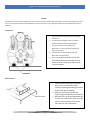
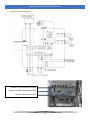
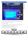
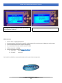
The Eaton Compressor Smart Air REV032921 is a powerful and versatile air compressor that is perfect for a wide range of applications. With its variable speed drive (VSD) technology, the Smart Air REV032921 can automatically adjust its speed to match the demand for air, which can save you energy and money. The Smart Air REV032921 also features an automatic tank drain, which helps to prevent moisture from building up in the tank.
Additionally, the Smart Air REV032921 is equipped with several safety features, including a pressure relief valve and a thermal overload protector. These features help to ensure that the compressor operates safely and efficiently.
Eaton Compressor Smart Air REV032921
The Eaton Compressor Smart Air REV032921 is a powerful and versatile air compressor that is perfect for a wide range of applications. With its variable speed drive (VSD) technology, the Smart Air REV032921 can automatically adjust its speed to match the demand for air, which can save you energy and money. The Smart Air REV032921 also features an automatic tank drain, which helps to prevent moisture from building up in the tank.
Additionally, the Smart Air REV032921 is equipped with several safety features, including a pressure relief valve and a thermal overload protector. These features help to ensure that the compressor operates safely and efficiently.


-
 1
1
-
 2
2
-
 3
3
-
 4
4
-
 5
5
-
 6
6
-
 7
7
-
 8
8
-
 9
9
-
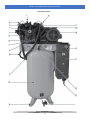 10
10
-
 11
11
-
 12
12
-
 13
13
-
 14
14
-
 15
15
-
 16
16
-
 17
17
-
 18
18
-
 19
19
-
 20
20
-
 21
21
-
 22
22
-
 23
23
-
 24
24
-
 25
25
-
 26
26
-
 27
27
-
 28
28
-
 29
29
-
 30
30
-
 31
31
-
 32
32
-
 33
33
-
 34
34


Eaton Compressor Smart Air REV032921 Owner's manual
- Category
- Air compressors
- Type
- Owner's manual
Eaton Compressor Smart Air REV032921
The Eaton Compressor Smart Air REV032921 is a powerful and versatile air compressor that is perfect for a wide range of applications. With its variable speed drive (VSD) technology, the Smart Air REV032921 can automatically adjust its speed to match the demand for air, which can save you energy and money. The Smart Air REV032921 also features an automatic tank drain, which helps to prevent moisture from building up in the tank.
Additionally, the Smart Air REV032921 is equipped with several safety features, including a pressure relief valve and a thermal overload protector. These features help to ensure that the compressor operates safely and efficiently.
Ask a question and I''ll find the answer in the document
Finding information in a document is now easier with AI
Related papers
-
 Eaton Compressor PISTON – REV022621 Owner's manual
-
 Eaton Compressor FREIGHT TRAIN REV081321 Owner's manual
-
Eaton Rotary Screw User manual
-
 Eaton Compressor 25HP V4 Piston Air Compressor Owner's manual
-
 Eaton Compressor 15HP 3 Cylinder Piston Air Compressor Owner's manual
-
 Eaton Compressor POLAR AIR PP10V120Y1 User manual
-
 Eaton Compressor 20HP 3 Cylinder Piston Air Compressor Owner's manual
-
 Eaton Compressor 7.5HP 3 Cylinder Piston Air Compressor Owner's manual
-
 Eaton Compressor 5HP Inline Piston Air Compressor Owner's manual
-
 Eaton Compressor 7.5HP V4 Piston Air Compressor Owner's manual


Other documents
-
Husky C602H Installation guide
-
Global Industrial B2811234 User manual
-
Emax HRS0200001 User manual
-
Cal Flame ERSK150003 Operating instructions
-
JET 506601 User manual
-
-
Husky C803H Installation guide
-
Johnson Controls York YCIV0207 Installation Operation & Maintenance
-
Ingersoll-Rand NIRVANA IRN90K–CC Operation and Maintenance Manual
-
Trane SCWMN07L Installation, Operation and Maintenance Manual