ANZZI TL-MBSRN201WH Installation guide

Type
Installation guide

This manual is also suitable for

ANZZI SOFT CLOSE MANUAL BIDET SEAT
TL-MBSEL200WH TL-MBSRN201WH
ITEM: TL-MBSEL200WH
TL-MBSRN201WH
INSTALL & OPERATION MANUAL
V1.1
DONT WAIT!
REGISTER NOW!
Register your product within 90 days to ensure your product is
coverage.
Mail in the completed registry card (Pg. 2) or register online
at www.swcorp.com/register.
®
2
Have questions? Call us at 1-844-44-ANZZI or visit us at www.ANZZI.com
PRODUCT REGISTRATION*
IMPORTANT: YOUR WARRANTY WILL NOT BE RECOGNIZED UNLESS THIS CARD IS
FULLY COMPLETED AND RETURNED OR ONLINE REGISTRATION IS COMPLETED.
1.
Register online at
www.swcorp.com/register.
You will be asked to fill out the same
information you would in the registration card. Registering online is fast, secure and
ensures we receive your information.
2. Complete, cut-out and mail the registration card below. By returning this registration
card we confirm the date of purchase for your new product. This confirmation will allow
us to process any warranty claims.
Mail the card to: 5701 NW 35 Avenue, Miami, FL 33142
Product Registration Card
Name ..................................................................................... Address ...........................................................................................................................
City ............................................... State ........................... Zip ..............................
Phone ........................................... Email ....................................................................
Date of Purchase...........................
Installer’s Name ..................................................................... Phone ................................................................................
I have read the Owner’s Manual carefully and understand and agree that any installation, operation or maintenance of the product must be done
strictly in accordance with instructions and guidelines contained in the owner’s manual and installation guide.
Signature____________________________________________________________Date ______________________________________________
CUT ALONG
DOTTED LINE.
®
3
Have questions? Call us at 1-844-44-ANZZI or visit us at www.ANZZI.com
TL-MBSEL200WH
TL-MBSRN201WH
≥13.8in
≥19.5in
B5.3 6.9 in
14.6in
A =16.117.9 in
2in
10.7in
8.3in
14.1in
18.9 in
2.4in
0.2in
≥14.6in
≥20.5in
B5.3 6.9 in
19.7 in
2.4in
0.2in
A=16.918.7in
11.2in
8.3in
2.3in
14.6in
14.1in
4
Have questions? Call us at 1-844-44-ANZZI or visit us at www.ANZZI.com
Left inflow
Right inflow
Water tank
Knob
Angle valve
Water inlet hose
Tee joint
Water supply pipe
Remove hipon
Toilet lid
Toilet seat
Nozzle (Hip cleaning)
Nozzle (Lower body cleaning)
Toilet base
Part Name
General Product Drawing
5
Have questions? Call us at 1-844-44-ANZZI or visit us at www.ANZZI.com
1.Cover plate
3.Fix parts
4.Tee joint 5.Inlet hose
Expansion bolt (2)Connecting bolt2
Adjusting piece (2)
2.Install the template
6.Installation Guide
/User Manual
Installation Guide
/User Manual
filter screen
Nut (2)
fixing plate (1)
or
Parts
Note: There are two installation methods for this product. The expansion bolt is the configuration
of the recommended installation method, and the hiperfly nut is the configuration of another
installation method. Please choose in practice.
6
Have questions? Call us at 1-844-44-ANZZI or visit us at www.ANZZI.com
Installation preparation
Installation
Please read this manual carefully for correct installation.
Installation considerations
Installation steps
1.Water pressure range: 0.07-0.8MPa(10116PSI), please use according to the instructions.
2.The angle valve shall be close to the installation and disassembly position of this product.
1.Insert the connecting bolt into the adjusting piece.
Insert the connecting bolt into the hole of the adjusting piece in the direction shown in the figure.
2.Insert the adjusting piece and connecting bolt into the fixing plate.
As shown in the figure, insert the connecting bolts with the adjusting
pieces into the holes of the fixing plate respectively.
7
Have questions? Call us at 1-844-44-ANZZI or visit us at www.ANZZI.com
Fixing slot at the bottom
of the product
Installation steps
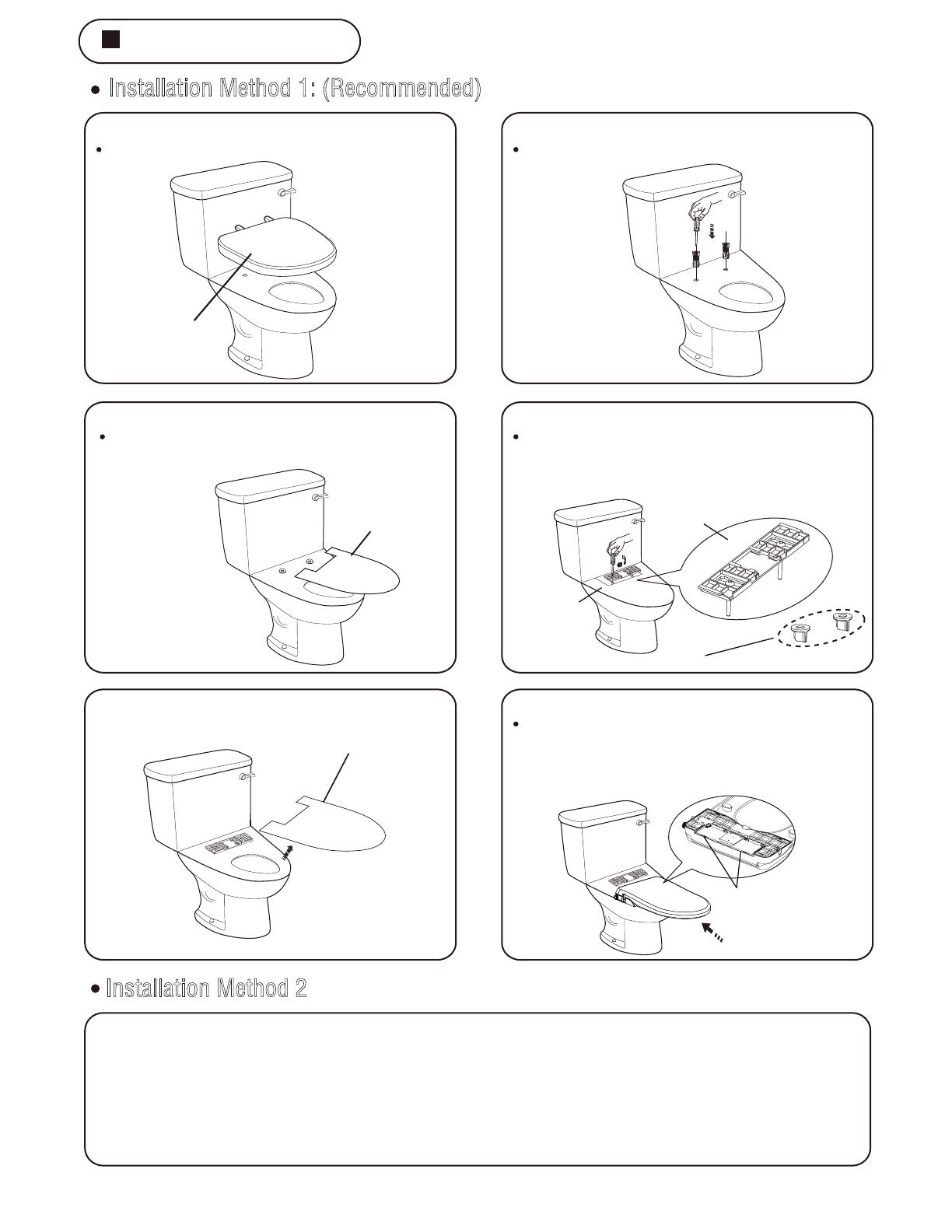
Installation Method 1: (Recommended)
1.Remove the old cover plate.
3.Install the template.
5.Remove the installation template.
6.Install the product.
Cover plate
Install Template
2.Install expansion bolts.
4.Install the fixing plate and lock it.
Loosen nuts linking the cover and remove the
cover.
Press the expansion bolts into the ceramic holes
respectively
as shown in
the figure.
As shown in the figure, place the installation
template on the ceramic.
Align the fixing slot at the bottom of the product
with the fixing plate, push the product in the
direction shown in the figure, push it to the
bottom, and the installation is completed.
Align the fixing plate with the ceramic hole as
shown in the figure, then adjust the positions
of the connecting bolt and the adjusting piece
to align the connecting bolt with the expansion
bolt, and lock the fixing plate.
Text FRONT Forward
Install Template
Install template
Hiperfly nuts are used for the second mounting mode
Installation Method 2
1.Remove the old toilet lid and toilet seat and place the installation template on ceramic
(see Article 1 and 3 of the first method).
2.Align the fixing plate as shown in the figure (the fourth point of the first method is shown in the figure)
with the ceramic hole, then adjust the positions of the connecting bolt and the adjusting piece, lock the
hiperfly nut from the lower end of the ceramic to the upper end, and fix the fixing plate.
3.For the rest of the installation steps, see Article 5 and 6 of the first method to complete the installation.
8
Have questions? Call us at 1-844-44-ANZZI or visit us at www.ANZZI.com
Rubber pad
Filter
Connecting water pipes
1
3
2
2.Connect the water supply hose to the tee joint.
Throttle valve
1.
Note: The throttle cover and throttle 0-RING in the throttle valve shall be removed in the following two cases.
a.When the inflow pressure is less than or equal to 0.05 MPa dynamic pressure. (e. G., domestic water tower, etc.)
b.When the cover plate is installed and used, the nozzle cannot be sprayed normally.
Disassembly steps1Use pliers and other tools to clip the throttle valve out of the water inlet pipe.
2Remove throttle cover and throttle 0-RING. (Sealed 0-RING to be retained)
3Reinstall the throttle valve into the inlet pipe.
Special reminder:
When the inlet pressure is ≥0.1MPa, the throttle cover and throttle 0-RING must be retained
in the throttle valve.
Throttle bonnet
Throttle 0-RING
Sealed 0-RING
4.
3.
Prohibit
1.It is strictly prohibited to move products from the toilet lid, which is easy to
cause mechanical failure.
2.It is strictly prohibited to receive hot water above 40 and cold water that
will freeze.
Close the angle valve and remove the water supply hose connected to the
water tank.
The tee joint is connected to the angle valve and ensures that the
rubber sealing ring is installed therein.
Open the angle valve to check for
water leakage.
After inserting the filters and rubber pads
at both ends of the water inlet hose into
the water inlet hose, connect the tee joint
and the cover plate.
9
Have questions? Call us at 1-844-44-ANZZI or visit us at www.ANZZI.com
Operation Method
Stop cleaning and self-cleaning function (self-cleaning function is optional)
25˚
25˚
25˚
25˚
90˚
Hip cleaning function
Turn the knob from the vertical gear in the direction shown (clockwise).
Hip cleaning tut mouth stretch out,
spray water cleaning.
The flow rate varies with the
rotation of the knob.
Low flow
High flow
Lower body cleaning function (for women)
Turn the knob from the vertical gear in the direction shown (counterclockwise).
The lower body cleaning nozzle
extends out and sprays water for
cleaning.
The flow rate varies with the
rotation of the knob.
Low flow
High flow
Turn the knob to the vertical (90°) position to turn off the cleaning function.
Before each use, the knob can be turned to the 25° gear and stayed for a
few seconds to clean the nozzle. When the product is connected with
warm water, it can also play a role in
emptying cold water.
After each use, the nozzle can clean
itself. If additional cleaning is needed
for the nozzle, please turn the knob
to the 25° gear and stay for a few
seconds, then turn back to the vertical
(90°) gear to turn off the self-cleaning function.
10
Have questions? Call us at 1-844-44-ANZZI or visit us at www.ANZZI.com
Throttle valve
Cleaning and Disassembly
1.Clean the external parts of the product.
3.Clean filter screen and throttle valve 4.Remove the product cover plate.
2.Clean the nozzle.
Use a smooth sponge or cloth with a neutral
cleaner to clean the product. It is forbidden to
use hydrogen chloride cleaner, diluent, benzene,
sandpaper, polishing agent, perfume, pesticide
and other cleaning products.
Gently pull out the nozzle and use a smooth
cloth, sponge or toothbrush to remove the
kitchen cleaner and wipe the nozzle.
Insecticides
Diluent
Sandpaper
2Please clean throttle valve 0 ~ RING. (Refer
to Step 2 on Page 5 for removal and
installation of throttle valve 0-RING)
Braided hose
Filter screen
If you feel that the water flow is less than
normal, please close the angle valve. )
1Separate the water inlet hose from the
product and clean both ends of the filter
screen of the water inlet hose with a brush.
Close the upper cover of the product, press
the disassembly button with your hand, and
pull out the cover plate of the product in the
direction of the arrow shown in the figure to
disassemble.
Remove the button
11
Have questions? Call us at 1-844-44-ANZZI or visit us at www.ANZZI.com
A
B
C
1.Knob replacement.
3.Throttle valve replacement. 4.Water inlet pipe leakage maintenance.
2.Nozzle replacement.
5
Maintenance
2Pull out the old knob directly along the axis
as shown in Figure B.
1Turn the knob to the maximum position in
the hip washing direction as shown in Figure A.
1After pulling out the conduit as shown in
Figure A, grab the conduit and pull out the old
nozzle directly along the axis.
1Turn the knob to the working position and
clip the throttle valve out of the water inlet pipe
with pliers and other tools.
2Press the new throttle assembly into the t
hrottle valve at the bottom of the inlet pipe and
replace it. Then turn the knob to the closed
position.
Throttle valve
If there is water leakage at both ends of the
inlet pipe, please tighten the nut again.
A
B
Sprinkler head
3As shown in Figure C, pull out the new knob
along the old knob and insert the rib into the
corresponding control valve slot. After hearing
the "click" sound, the installation is completed.
TL-MBSEL200WH
0.1 - 0.5 GPM
0.1 - 0.5 GPM
TL-MBSEL200WHTL-MBSRN201WH
TL-MBSRN201WH
TL-MBSEL200WH
TL-MBSRN201WH
4.6LB
4.4LB
14.6”X18.7”X2.4”
14.6”X19.7”X2.4”
6
Problem Judgment and Product Specications
Problem Judgment and Troubleshooting
Failure Reason Solution
Inadequate flushing
water
1.Low water pressure
When washing, quickly turn the knob to the maximum
gear of "washing" or "women washing"
If the water pressure is lower than the minimum water
pressure of 0.07 MPa used by the product, please
contact relevant departments to solve the water
pressure problem of water supply.
2.Low water pressure
1.Angle valve closed
2.Tee filter screen is blocked
3.The filter screen of the water
inlet pipe is blocked.
4.Nozzle blockage
Hip washing or
woman washing
can't get out of
water.
When in use,
the base leaks
Open angle valve
Cleaning tee filter screen
Clean the filter screen of the water inlet pipe
Remove nozzle for cleaning
Increase external water pressure
5.External water pressure is too low
Excessive external water pressure
The maximum water pressure used by the product is 0.8
MPa. If the water pressure exceeds 0.8 MPa, please
contact relevant departments to solve the water
pressure problem.
If the above corresponding treatment still cannot be used normally, or if there is any phenomenon other than
this table, please contact the local designated maintenance center for maintenance.
Warning
Do not disassemble, repair or modify the product by yourself.
Product Specifications
Category Description
Model
Hip cleaning flow rate
Women's washing flow rate
Anti-backflow device
Water supply system
One-way valve, vacuum switch
Water-pipe supply
Water pressure requirement
Static pressure: 0.07-0.8 MPa; Dynamic pressure: above 0.03 MPa
Dimensions
Weight
12
Have questions? Call us at 1-844-44-ANZZI or visit us at www.ANZZI.com
  • Page 1 1
  • Page 2 2
  • Page 3 3
  • Page 4 4
  • Page 5 5
  • Page 6 6
  • Page 7 7
  • Page 8 8
  • Page 9 9
  • Page 10 10
  • Page 11 11
  • Page 12 12

ANZZI TL-MBSRN201WH Installation guide

Type
Installation guide
This manual is also suitable for

Ask a question and I''ll find the answer in the document

Finding information in a document is now easier with AI