Page is loading ...

Page 1 of 16 2475DA2, 2442-422, 2442-522 Rev: 10/19/2015 4:26 PM
Ballast Dimmer
INSTEON
®
Remote Control 0-10VDC Ballast Dimmer
Owner’s Manual
2475DA2 (US)

Page 2 of 16 2475DA2, 2442-422, 2442-522 Rev: 10/19/2015 4:26 PM
About Ballast Dimmer ................................................................................................................................3!
Features and Benefits ................................................................................................................................3!
Optional Accessories ................................................................................................................................3!
Getting Started............................................................................................................................................3!
Installing Ballast Dimmer...........................................................................................................................4!
Identifying the Electrical Wires in Your Home (North America only).........................................................4!
Identifying the Electrical Wires in Your Home (Europe/Australia/New Zealand).......................................4!
12BInstall Ballast Dimmer for Dimmable Ballast.......................................................................................5!
12BInstalling Ballast Dimmer in Dual-Relay Mode ...................................................................................6!
INSTEON Setup...........................................................................................................................................7!
INSTEON Controllers, Responders and Links..........................................................................................7!
Make Ballast Dimmer a Responder ..........................................................................................................7!
Changing Operating Modes (Dimmer or Switch) ......................................................................................8!
Scenes ......................................................................................................................................................8!
X10 Setup ....................................................................................................................................................9!
Add X10 Address ......................................................................................................................................9!
Remove X10 Address ...............................................................................................................................9!
4B Advanced Setup ....................................................................................................................................9!
Make Ballast Dimmer a Controller ............................................................................................................9!
Remove Ballast Dimmer as a Responder.................................................................................................9!
Remove Ballast Dimmer as a Controller.................................................................................................10!
Factory Reset..........................................................................................................................................10!
Restoring Power .....................................................................................................................................10!
Specifications ...........................................................................................................................................11!
Troubleshooting .......................................................................................................................................14!
Phase Bridge Detect Beacon/RF Range Test ........................................................................................14!
8BCertification and Warranty ..................................................................................................................15!
19BUCertification ....................................................................................................................................15!
20BUFCC and Industry Canada Compliance Statement........................................................................15!
21BULimited Warranty............................................................................................................................15!
22BULimitations ..................................................................................................................................15!

Page 3 of 16 2475DA2, 2442-422, 2442-522 Rev: 10/19/2015 4:26 PM
About Ballast Dimmer
This in-line ballast control module supports two different operational modes: dimmer and dual-relay. For use in new construction
or retrofit (inside or outside the fixture) where saving energy is a priority.
RJ-10 Mini-modular jack pin-outs:
Pin 4
(Left side)
Pin 3
Pin 2
Pin 1
Ground
Group 1 - 2
Group 3-4
12-15VDC
Group 1: triggers when switch between pin 3 & 4 is closed
Group 2: triggers when switch between pin 3 & 4 is opened
Group 3: triggers when switch between pin 2 & 4 is closed
Group 4: triggers when switch between pin 2 & 4 is opened
12B
Features and Benefits
• Controls dimmable ballasts with 0-10VDC input
• Dual-relay load output offers control of two non-dimmable ballasts up to 5A each
• Supports 100VAC to 277VAC
• 50/60Hz (auto-detect) for international compatibility
• Beeper for setup ease
• All settings stored in stable memory, even through power outages
• Two year warranty
In the Box
Tools Needed
Optional Accessories
Ballast Dimmer
Slotted screwdriver
Keypad Dimmer
Quick Start Guide
Phillips screwdriver
Dimmer Switch
Mounting Screws
Wire cutter/stripper
INSTEON Hub
Two extra INSTEON ID labels
Voltage meter
Mini Remote
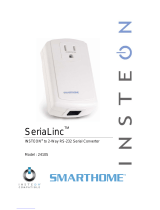
Getting Started
Line
(black)
Neutral
(white)
Set button
Status LED
Load 2
Load 1
0-10VDC +
DC ground
RJ-10 jack

Page 4 of 16 2475DA2, 2442-422, 2442-522 Rev: 10/19/2015 4:26 PM
Map out the wall switch and load that you are going to remotely operate. Keep in mind that you are going to replace
the existing wall switch with a keypad or another INSTEON controller where both are wired to the same constant hot
line using the existing wiring.
Installing Ballast Dimmer
CAUTIONS AND WARNINGS
Read and understand these instructions before installing and retain them for future reference.
This product is intended for installation in accordance with the National Electric Code and local regulations in the United States or
the Canadian Electrical Code and local regulations in Canada. Use indoors only. This product is not designed or approved for
use on power lines other than 100VAC- 277VAC 50/60Hz, single phase. Attempting to use this product on non-approved power
lines may have hazardous consequences.
- Use only indoors or in an outdoor rated box
- Use with Branch Circuit Breakers 15 Amps or fewer
- Be sure that you have turned off the circuit breaker or removed the fuse for the circuit you are installing this product into.
Installing this product with the power on will expose you to dangerous voltages.
- Connect using only copper or copper-clad wire
- This product may feel warm during operation. The amount of heat generated is within approved limits and poses no
hazards. To minimize heat buildup, ensure the area surrounding the rear of this product is as clear of clutter as possible.
- Each INSTEON product is assigned a unique INSTEON ID, which is printed on the product’s label.
- To reduce the risk of overheating and possible damage to other equipment, do not use this product to control loads in
excess of the specified maximum(s) or, install in locations with electricity specifications which are outside of the product’s
specifications.
Identifying the Electrical Wires in Your Home (North America only)
- Line: usually black (may also be called hot, live or power), carries 120VAC electricity into the wall box
- Neutral: usually white or white wire bundle, commonly daisy-chained from box to box
- Load: usually black, from a separate cable jacket
- Ground: bare copper wire or metal fixture (if grounded)
Identifying the Electrical Wires in Your Home (Europe/Australia/New Zealand)
- As wire colors vary from country to country, make sure you always check your electrical wires with a voltage meter to
correctly identify line, load, neutral and ground wires
- If you have any questions, consult an electrician or your electricity supplier to learn more about your country’s wiring colors
and labels
IMPORTANT!
If you have any difficulties or questions, consult an electrician. If you are not knowledgeable about, and comfortable with,
electrical circuitry, you should have a qualified electrician install the product for you.

Page 5 of 16 2475DA2, 2442-422, 2442-522 Rev: 10/19/2015 4:26 PM
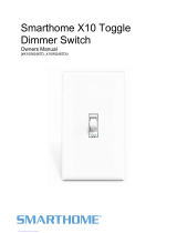
12BInstall Ballast Dimmer for Dimmable Ballast
Note: use with branch circuit breakers 15 Amperes or fewer.
1) Write down the INSTEON ID found on the front of the unit (XX.XX.XX)
2) Turn off breaker/fuse and verify that the power is off
3) Disconnect wires from existing switch
4) Connect wires per diagram.
5) At the ballast location, disconnect the wires from the fixture you will be controlling and ensure that you have ½ inch of bare
wire on the ends
6) See the diagram to identify and connect the line, load, neutral DC(+) and DC(-) wires on Ballast Dimmer. Be sure you have
correctly identified the wires in the junction box before connecting them.
7) After ensuring wires are firmly connected and that there is no exposed wire, turn on breaker/fuse
After a few seconds, load will turn on
8) Test Ballast Dimmer connection by tapping set button a couple times
Ballast Dimmer load will respond appropriately
9) Link Ballast Dimmer to your INSTEON keypad or other INSTEON controller. See Make Ballast Dimmer a Responder.
10) Gently place Ballast Dimmer into the fixture box, making sure nothing could accidentally press the set button
11) Reinstall the fixture
12) Use the included INSTEON ID stickers to keep track of the modules location
The hot feeding this circuit is paralleled from the hot connection
on the keypad keeping both devices powered at all times and
using existing wiring.

Page 6 of 16 2475DA2, 2442-422, 2442-522 Rev: 10/19/2015 4:26 PM
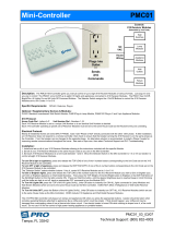
12BInstalling Ballast Dimmer in Dual-Relay Mode
1) Write down the INTEON ID found on the front of the unit (XX.XX.XX)
2) Turn off breaker/fuse and verify that the power is off
3) Disconnect wires from existing switch
4) Connect the wires per diagram
5) At the ballast location, disconnect the wires from the fixture you will be controlling and ensure that you have ½ inch of bare
wire on the ends
6) See the diagram to identify and connect the line, load 1, load 2 and neutral wires on Ballast Dimmer. Be sure you have
correctly identified the wires in the junction box before connecting them.
7) Place wire nuts on the unused gray and purple wires
8) After ensuring wires are firmly connected and that there is no exposed wire, turn on breaker/fuse
After a few seconds, load will turn on
9) Change to dual relay mode:
a. Press and hold set button until it beeps
LED will start blinking green
b. Tap set button twice
Ballast Dimmer will beep once and LED will stop blinking
10) Test the Ballast Dimmer connection by tapping set button a couple times
11) Link Ballast Dimmer to your INSTEON keypad or other INSTEON controller. See Make Ballast Dimmer a Responder.
12) Gently place Ballast Dimmer into the fixture box, making sure nothing could accidentally press the set button
13) Reinstall the fixture
14) Use the included INSTEON ID stickers to keep track of the modules location
Diagram showing only the non-dimming connection to
ballast 1 and 2.
The hot feeding this circuit is paralleled from the hot
connection on the keypad keeping both devices
powered at all times and using existing wiring.

Page 7 of 16 2475DA2, 2442-422, 2442-522 Rev: 10/19/2015 4:26 PM
INSTEON Setup
Some products have subtle differences in their setup procedures. Please refer to the other devices’ owner’s manuals
for details.
INSTEON Controllers, Responders and Links
Let’s define a few terms.
• The INSTEON “transmitter” is called a controller
• The INSTEON “receiver” is called a responder
• The association between the controller and responder is called a link
Please note that a link is one way. If you wish to have control “the other way,” simply repeat link setup process “the
other way.” Most INSTEON devices can store hundreds of links. Furthermore, a controller can simultaneously control
from 1 to hundreds of responders using what are called groups and scenes. Each link can have its own properties
(e.g. 50% brightness at a 4-second ramp rate).
Make Ballast Dimmer a Responder
Follow the steps below to create a link, enabling another INSTEON device to control Ballast Dimmer.
1) Use Ballast Dimmer set button to set the load to the state you wish to activate from the controller (turn it on if you
wish it to be on when the controller activates the scene, etc.)
2) Press and hold the scene controller button until it beeps
1
3) Press and hold Ballast Dimmer set button until it double-beeps
Controller will double-beep
2
and LED will stop blinking
4) Test by tapping controller button on and off
Load connected to Ballast Dimmer will respond appropriately
Note:
- If you wish Ballast Dimmer load to be off when the link is activated (such as for an “all off” scene), turn the load
off in step #2
1
If the controller does not have a beeper, wait until its LED begins blinking
2
Most models
Controller
Responder
Link
Ballast
Dimmer
(responder)
Controller

Page 8 of 16 2475DA2, 2442-422, 2442-522 Rev: 10/19/2015 4:26 PM
Changing Operating Modes (Dimmer or Switch)
Relay Mode:
By default, the Ballast Dimmer comes in Dimmer mode. Use the Relay mode for use with non-dimmable ballasts.
Ballast Dimmer provides two relays to control individual ballasts or a multi-state ballast light fixture. In the multi-state
ballast light fixture, either half could be off or on allowing brightness at 0%, 50%, and 100%. This mode also allows a
form of course dimming as a combination of the relays: Off = both open, 50% = 1 closed/1 open, 100% = both
closed.
To change to relay mode, follow these steps:
1) Press and hold set button until it beeps
LED will start blinking green
2) Quickly tap the set button twice
Ballast Dimmer will beep once and LED will stop blinking
Dimmer Mode:
Used with dimmable ballasts that dim based on a DC control signal that ranges from 0 to 10 V DC. When the
dimmer goes down to a preset voltage, the load control relay will open removing power from the load (turning ballast
off entirely). To change back to Dimmer Mode, follow these steps:
1) Press and hold set button until it beeps
LED will start blinking green
2) Quickly tap the set button three times
Ballast Dimmer will double-beep and LED will stop blinking
To determine current operation mode, tap Ballast Dimmer set button 4 times:
• Red, Green, Red, Green = Dimmer Mode
• Red, Green, Green, Green = Relay Mode
Scenes
INSTEON scenes allow a controller to conveniently adjust multiple responders to any number of desired levels, all
simultaneously. Software is recommended when setting up and maintaining scenes, especially larger scenes.
Create a scene with 1 controller and Ballast Dimmer as a member
1) Press and hold controller button until it beeps
Controller LED will start blinking
2) Tap controller set button
Controller LED will start double-blinking
3) Tap Ballast Dimmer on and adjust to desired scene state
Ballast Dimmer LED will turn green
4) Press and hold Ballast Dimmer set button until it double-beeps
5) For each additional scene member
a. Adjust member to desired scene brightness/state
b. Press and hold set button until it double-beeps
6) Press and hold controller set button until it double-beeps
Controller LED will stop blinking
7) Test by tapping controller button on and off
Ballast Dimmer and other scene responders will all respond appropriately

Page 9 of 16 2475DA2, 2442-422, 2442-522 Rev: 10/19/2015 4:26 PM
X10 Setup
Ballast Dimmer ships with no X10 address assigned.
Add X10 Address
1) Press and hold set button until it beeps
LED will start blinking green
2) Send the desired X10 address (plus on if desired) 3 times (e.g. send B5, BON, B5, BON, B5, BON)
Ballast Dimmer will double-beep and LED will stop blinking
3) Test by sending X10 on and off commands
Load will turn on and off
Remove X10 Address
1) Press and hold set button until it beeps
LED will start blinking green
2) Press and hold set button until it beeps
LED will start blinking red
3) Send any X10 address (plus on if desired) 3 times (e.g. send B5, BON, B5, BON, B5, BON)
Ballast Dimmer will double-beep and LED will stop blinking
4) Test by sending the old X10 address on and off commands
Ballast Dimmer will not respond
4B Advanced Setup
Make Ballast Dimmer a Controller
Note: you must perform these steps before reinstalling.
1) Press and hold Ballast Dimmer set button until it beeps
Ballast Dimmer LED will start blinking green
You will have four minutes to complete the next steps before linking mode times out
2) Adjust responder to desired state
1
3) Press and hold responder set button until it double-beeps
Ballast Dimmer will double-beep and its LED will stop blinking
2
4) Test link by tapping or pressing and holding Ballast Dimmer on/off buttons to turn on/off or brighten/dim
Responder will respond appropriately
Remove Ballast Dimmer as a Responder
If you no longer want a controller button to control Ballast Dimmer follow these directions. Note: If you ever wish to
un-install Ballast Dimmer, it is important that you remove all Ballast Dimmer responder links. Otherwise, controllers
will retry commands repetitively, creating network delays.
1) Press and hold controller button until it beeps
3
LED will start blinking green
2) press and hold controller button until it beeps a second time
LED will start blinking red
3) Press and hold Ballast Dimmer set button until it double-beeps
Controller LED will stop blinking
4) Test by tapping controller button on and off
Ballast Dimmer will no longer respond
1
If responder is a multi-scene device such as a keypad, tap scene button you wish to control until the LED is in the desired scene state (on or off).
2
If either controller or responder LED continues blinking, the addition failed. Tap device’s set button until LED stops blinking and try linking again.
3
For devices without beepers hold until its LED begins blinking (this may take 10+ seconds)

Page 10 of 16 2475DA2, 2442-422, 2442-522 Rev: 10/19/2015 4:26 PM
Remove Ballast Dimmer as a Controller
If you no longer want Ballast Dimmer to control another device (or are removing Ballast Dimmer) it is important that
you follow the instructions below for each responder.
1) Press and hold Ballast Dimmer set button until it beeps
LED will start blinking green
2) Press and hold Ballast Dimmer set button until it beeps a second time
LED will start blinking red
3) Press and hold responder set button until it double-beeps (or LED blinks)
Ballast Dimmer will double-beep and LED will stop blinking
4) Test by tapping Ballast Dimmer on and off
Responder will not respond
Factory Reset
NOTE: All settings and scenes will be erased
1) Disconnect Ballast Dimmer from power for about 10 seconds
2) While holding down the set button, reconnect power to Ballast Dimmer, making sure not to let go of the set
button
Ballast Dimmer will beep and the status LED will turn on solid green
3) Continue to hold down the set button for 3 seconds and then release
Ballast Dimmer will double-beep and the load will turn on
Restoring Power
Ballast Dimmer stores all of its settings, such as links to other INSTEON devices, with non-volatile memory. Because
settings are saved in this non-volatile memory, they will not be lost in the event of a power failure.
In the event of a power loss Ballast Dimmer will automatically return the load to the state it had before power was
interrupted.

Page 11 of 16 2475DA2, 2442-422, 2442-522 Rev: 10/19/2015 4:26 PM
Specifications
General
Product Name
Ballast Dimmer Relay – INSTEON Remote Control Ballast
Dimmer On/Off Switch (Dual-Band)
Brand
INSTEON
Manufacturer Product Number
2475DA2 (US)
2446-422 (EU)
2446-522 (AUS/NZ)
UPC
813922011425 (US)
813922012897 (EU)
813922012903 (AZ)
Patent Number
7,345,998 US, International Patents Granted and Pending
Warranty
2 Years, Limited
INSTEON
INSTEON ID
1
INSTEON
400 responder groups and 1 controller group
Maximum Scene Memberships
400 (Combined Controller + Responder)
INSTEON Device Category
0x01 Dimmable Lighting Control (All Frequencies)
2475DA2 (915MHz
0x25
2446-422 (869MHz)
0x3D
INSTEON Device Subcategory
2446-522 (921MHz)
0x3E
Load brightness levels
32 locally (256 with software)
Status LED
Green when load is on, red when load is off
LED brightness
Adjustable, from off to bright via software
Local on-level (Dimming Mode)
Adjustable, 32 fixed brightness levels or resume dim
Local ramp-rate (Dimming Mode)
Adjustable from 0.1 seconds to 9 seconds locally (0.1 seconds
to 9 minutes via software)
Local control
Yes
Commands supported as controller
On
On
Off
Fast-on
Fast-off
Begin bright
Begin dim
End bright
End dim
Commands Supported as responder
Incremental bright
Incremental dim
Software Configurable
Yes
RF Range
Up to 50 meters open air
Phase detect beacon
Yes

Page 12 of 16 2475DA2, 2442-422, 2442-522 Rev: 10/19/2015 4:26 PM
X10 Support
Yes
X10 Addresses
Any 1 of 256 (unassigned by default)
Mechanical
Mounting
Behind switch or outlet, or above light fixture in a single-gang
electrical box
Analog + 0-10V Control (Gray wire)
Analog - 0-10V Control (purple wire)
Line
Neutral
Load 1
Wires
Load 2
Set Button
1
Beeper
Yes
Beep on button press
Optional (off by default)
LED
1, green/red
Dimensions
171mm (wide), 30mm (high), 35mm (deep)
6.75-in. (wide), 1.2-in. (high), 1.4-in. (deep)
Weight
5.1 ounces
Operating Environment
Indoors
Operating Temperature Range
32º F – 104º F (0º C – 40º C)
Operating Humidity Range
0-90% relative humidity, non-condensing
Storage conditions
-4º F to +158º F (-20º C – 70º C)
Case Color
White
Plastic
UV stabilized polycarbonate
Electrical
Voltage
100-277VAC ±10%
Frequency
50Hz/60Hz
Maximum Load
0-10VDC for connection to dimmable ballast
Load 1; 100 to 277VAC / 5Amps
Load 2; 100 to 277VAC / 5Amps
Hardwired remote control
RJ-10 Mini-modular jack four conductor
Hardwire port wiring
Pin 4
(Left side)
Pin 3
Pin 2
Pin 1
(Right side)
Ground
Group 1 - 2
Group 3-4
12-15VDC
Hardwire port triggering
Group 1: triggers when switch between Pin 3 & 4 is closed
Group 2: triggers when switch between Pin 3 & 4 is opened
Group 3: triggers when switch between Pin 2 & 4 is closed
Group 4: triggers when switch between Pin 2 & 4 is opened!
Retains all settings without power
Yes, saved in non-volatile EEPROM
Load Type(s)
Wired in ballasted dimming and non-dimming lighting loads
Retains all settings without power
Yes, saved in Non-volatile EEPROM
Standby power consumption
< 1 watt

Page 13 of 16 2475DA2, 2442-422, 2442-522 Rev: 10/19/2015 4:26 PM
Safety Approved
ETL, CE, C-Tick
Certifications
FCC 15.107, 15.109, 15.249
RSS 210
EN 300 220-2, 301 489-3
AS/NZS 4268, CISPR 22
UL 508
CSA C22.2#14
IEC 60669-2-1
FCC ID
SBP2475DA2

Page 14 of 16 2475DA2, 2442-422, 2442-522 Rev: 10/19/2015 4:26 PM
Troubleshooting
Problem
Possible Cause
Solution
Make sure the circuit breaker(s) are turned on.
The Status LED on
Ballast Dimmer is not
turning on and won’t
control the load.
Ballast Dimmer may not
be getting power.
Check the junction box wires to ensure all
connections are tight and no bare wires are
exposed.
The Controller might have
been reset without
removing Ballast Dimmer
from the scene.
Re-add Ballast Dimmer to the Controller scene.
The INSTEON signal may
be too weak.
Add additional INSTEON devices or move around
existing INSTEON devices. All INSTEON devices
act as INSTEON network repeaters.
Large appliances, such as
refrigerators or air
conditioners, may be
producing electrical noise
on the powerline.
Ballast Dimmer won’t
add to a scene or
work with a Controller.
Other electrical devices,
such as computers,
televisions, or power
strips, may be absorbing
the INSTEON signal.
Install a powerline noise filter to filter electrical
noise and minimize signal attenuation.
Remove any unused responders from the
Controller scene.
HINT: If you are using home automation software,
you can easily check scene membership and
remove devices that are no longer in use.
Ballast Dimmer is
taking a long time to
respond to a
Controller.
The Controller may be
sending commands to a
responder that is no
longer in use. Commands
for the unused responder
are being resent and
delaying the signal.
If the above doesn’t work, perform a factory reset
on the Controller.
The load turned on by
itself.
Another Controller or timer
could have triggered
Ballast Dimmer.
Factory reset Ballast Dimmer. See HResetting
Ballast Dimmer to its Factory Default Settings.
The Controller can
turn off Ballast
Dimmer but Ballast
Dimmer does not turn
on when I send an ON
command from the
Controller.
Ballast Dimmer may be
added to the scene in its
off state.
Re-add Ballast Dimmer to the Controller scene,
while the load is on. See HAdding Ballast Dimmer to
a scene as a responder.
Temporarily remove power from Ballast Dimmer,
usually by opening the breaker feeding it.
Ballast Dimmer is
locked up.
A surge or excessive
noise on the powerline
may have glitched it.
If the above doesn’t work, perform a factory reset.
See HResetting Ballast Dimmer to its Factory
Default SettingsH.
If you have tried these solutions, reviewed this Installation and Programming Guide, and still cannot resolve an issue
you are having with Ballast Dimmer, please call 866-243-8022
Phase Bridge Detect Beacon/RF Range Test
Ballast Dimmer automatically bridges the electrical phases in your home (via communications with other dual-band
devices on the “other phase”). This is only important in 2-phase homes with powerline-only INSTEON products or
buildings with both 2- and 3- phase circuits. The phase bridge detect beacon can also be used as an RF range test to

Page 15 of 16 2475DA2, 2442-422, 2442-522 Rev: 10/19/2015 4:26 PM
see if your devices are within communication range. You will need at least one other INSTEON dual-band device
installed.
1) Start Phase Bridging Detection Mode by tapping the set button on Ballast Dimmer four times, quickly
Ballast Dimmer will begin beeping continuously and the status LED will be solid green
2) Check the LED behavior of your other dual-band devices to see if they are on the opposite phase
If at least one of your other dual-band device LEDs is blinking green or is bright solid white or blue, the
device is on the opposite phase.
If none of your dual-band devices exhibit the behavior above, they are on the same electrical phase. Try one
or both of the following:
• Move a dual-band device to another location until it exhibits the desired behavior
• Follow steps 2 and 3 with your other dual-band devices to see if they are bridging the
phases
3) Tap the set button on Ballast Dimmer to exit Phase Bridging Detection mode
Ballast Dimmer will stop beeping and the status LED will remain solid green if the load is on or
turn solid red if it is off
8BCertification and Warranty
19BUCertification
This product has been thoroughly tested by Intertek - ETL SEMKO, a nationally recognized independent third-party testing laboratory. The North American ETL Listed
mark signifies that the device has been tested to and has met the requirements of a widely recognized consensus of U.S. and Canadian device safety standards, that
the manufacturing site has been audited, and that the manufacturer has agreed to a program of quarterly factory follow-up inspections to verify continued conformance.
20BUFCC and Industry Canada Compliance Statement
This device complies with FCC Rules Part 15C and Industry Canada RSS-210 (Rev. 8). Operation is subject to the following two conditions:
(1) This device may not cause harmful interference, and
(2) This device must accept any interference, including interference that may cause undesired operation of the device.
Le present appareil est conforme aux CNR d'Industrie Canada applicables aux appareils radio exempts de licence. L'exploitation est autorise aux deux conditions
suivantes:
(1) l'appareil ne doit pas produire de brouillage, et
(2) l'utilisateur de l'appareil doit accepter tout brouillage radiolectrique subi, mme si le brouillage est susceptible d'en compromettre le fonctionnement.
The digital circuitry of this device has been tested and found to comply with the limits for a Class B digital device, pursuant to Part 15.107 and 15.109 of the FCC Rules.
These limits are designed to provide reasonable protection against harmful interference in residential installations. This equipment generates, uses, and can radiate
radio frequency energy and, if not installed and used in accordance with the instructions, may cause harmful interference to radio and television reception. However,
there is no guarantee that interference will not occur in a particular installation. If this device does cause such interference, which can be verified by turning the device
off and on, the user is encouraged to eliminate the interference by one or more of the following measures:
- Re-orient or relocate the receiving antenna of the device experiencing the interference
- Increase the distance between this device and the receiver
- Connect the device to an AC outlet on a circuit different from the one that supplies power to the receiver
- Consult the dealer or an experienced radio/TV technician
WARNING: Changes or modifications to this device not expressly approved by the party responsible for compliance could void the user’s authority to operate the
equipment.
21BULimited Warranty
Seller warrants to the original consumer purchaser of this product that, for a period of two years from the date of purchase, this product will be free from defects in
material and workmanship and will perform in substantial conformity to the description of the product in this Owner’s Manual. This warranty shall not apply to defects or
errors caused by misuse or neglect. If the product is found to be defective in material or workmanship, or if the product does not perform as warranted above during the
warranty period, Seller will either repair it, replace it, or refund the purchase price, at its option, upon receipt of the product at the address below, postage prepaid, with
proof of the date of purchase and an explanation of the defect or error. The repair, replacement, or refund that is provided for above shall be the full extent of Seller’s
liability with respect to this product. For repair or replacement during the warranty period, call the INSTEON Support Line at 866-243-8022 with the Model # and
Revision # of the device to receive an RMA# and send the product, along with all other required materials to:
INSTEON
ATTN: Receiving
16542 Millikan Ave.
Irvine, CA 92606-5027
22BULimitations
The above warranty is in lieu of and Seller disclaims all other warranties, whether oral or written, express or implied, including any warranty or merchantability or fitness
for a particular purpose. Any implied warranty, including any warranty of merchantability or fitness for a particular purpose, which may not be disclaimed or supplanted
as provided above shall be limited to the two-year of the express warranty above. No other representation or claim of any nature by any person shall be binding upon
Seller or modify the terms of the above warranty and disclaimer.
Home automation devices have the risk of failure to operate, incorrect operation, or electrical or mechanical tampering. For optimal use, manually verify the device

Page 16 of 16 2475DA2, 2442-422, 2442-522 Rev: 10/19/2015 4:26 PM
state. Any home automation device should be viewed as a convenience, but not as a sole method for controlling your home.
In no event shall Seller be liable for special, incidental, consequential, or other damages resulting from possession or use of this device, including without limitation
damage to property and, to the extent permitted by law, personal injury, even if Seller knew or should have known of the possibility of such damages. Some states do
not allow limitations on how long an implied warranty lasts and/or the exclusion or limitation of damages, in which case the above limitations and/or exclusions may not
apply to you. You may also have other legal rights that may vary from state to state.
Protected under US and foreign patents (see www.insteon.com/patents)
© Copyright 2013 INSTEON, 16542 Millikan Ave., Irvine, CA 92606, 866-243-8022, Hwww.insteon.com
/