Page is loading ...

Installation & Maintenance
ECO-FLO
ENERGY RECOVERY VENTILATOR
READ AND SAVE THESE INSTRUCTIONS FOR FUTURE REFERENCE

The ECO-FLO Energy Recovery Ventilator is not explosion proof and should not
be used when a potentially explosive situation exists.
TO REDUCE THE RISK OF FIRE, ELECTRIC SHOCK, INJURY TO PERSONS, PLEASE
READ THESE INSTRUCTIONS CAREFULLY
1. Disconnect the ventilator from power mains prior to any installation or maintenance operations.
2. Use this ventilator only in the manner intended by the manufacturer.
If
you have questions,
contact the factory.
3. A qualied person(s) must perform installation work and electrical wiring in accordance with
all applicable codes and standards, including re-rated construction codes and standards.
4. While installing the ventilator, follow the safety regulations specied to the use of electric
tools.
5. The installation location of the ventilator must prevent unauthorized
a
ccess by unattended
children.
6. Do not use damaged equipment or cables when connecting the ventilator to power mains.
7. Do not lay the power cable of the ventilator in close proximity to heating equipment.
8. Protect electric parts of the ventilator against ingress of water. Do not touch the ventilator’s
controls or carry out installation and maintenance operation with wet hands. Do not wash
the ventil
ato
r with water.
9. The ventilator should never be operated in an area where there are hazardous and/or explosive
vapors.
10. Do not direct the airow produced by the ventilator toward open ame or ignition sources.
11. When cutting into walls, take care not to damage electrical wires and other hidden utilities.
12. Disconnect the ventilator from power supply and contact the Seller if unusual sounds are
generate
d or smoke is emitted.
13. The ventilator must be grounded.
1. Check for any visible damage to the ventilator before installing it. The housing internals must
be free of debris, which can damage the impeller blades.
2. For general ventilating use only. To avoid motor damage and noisy and/or unbalanced
impeller, keep the ventilator clean from drywall spray, construction dust, etc.
3. Misuse of the
v
entilator and/or any unauthorized design alterations or modifications voids
the warranty.
4. Avoid damaging the power cable. Do not bend or put foreign objects on the power cable.
5. For interior use only. Do not use where ambient temperature ranges from -4 F/-20 C up to
122 F/50 C. Relative humidity shall not exceed 80%. Do not operate the ventilator in aggressive
or explosive environments.
6. Not for
installation or operation by any person that is unable to follow these safety guidelines.
7. Do not open the ventilator during operation.
8. To ensure optimal airow, do not close or block the ventilator’s inlet or outlet. Do not sit or
put objects on the ventilator.
9. In case of continuous operation of the ventilator, periodically check the security of mounting.
SAFETY INSTRUCTIONS
2
WARNING
NOTICE
CAUTION

ECO-FLO ENERGY RECOVERY VENTILATOR
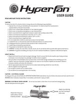
The ECO-FLO energy recovery ventilator is designed for through-the-wall mounting. The telescopic
design enables its installation in walls with various thickness (4.75” to 11.81”).
The delivery set includes:
• Ventilator – 1
• Set of small wall anchors and steel screws for the fan – 1
• Set of large wall anchors and brass screws for the hood – 1
• Remote control – 1
• Installati
on & Ma
intenance Manual
Ø6”
Ø6.19”
8.38”
9.44”
10.25”
4.75” - 11.81”5.69” 4” 5”11.81”
12.19”
3
1
7
5
6
4
2
3
1. Ventilation Unit must be installed on inner side of the wall. It is equipped with an automatic
shutter that closes the air duct during ventilation standby and prevents air backdraft.
2. Mounting Plate is used for installation of the ventilation unit on the wall and connecting it to
power mains.
3. Telescopic Duct with adjustable length is where the airflow straightener, ERV core and filters
are located.
4. Ai
rflow straightener eliminates air turbulence inside the ventilator.
5. Air Filters are designed to purify supply air and prevent the ingress of foreign objects into the
ERV core. Filters also prevent ERV core soiling.
6. ERV Core extracts heat from exhaust air to warm up supply airflow. The cord laid inside the
ERV core is designed to remove the core from the ventilator. The ERV core is heat insulated
w
ith a specially design
ed insulating material.
7. Exterior-Mounted Hood must be installed on the outer side of the wall. It directs air discharge
and prevents the ingress of water and other objects into the ventilator.
MODEL THERMAL
RECOVERY
SPEED RPM WATTS AMPS CFM SONES
@ 1M
SONES
@ 3M
SONES
(OUTDOOR)
POWER
SUPPLY
ECO-FLO* 90%
Low 610 3.80 0.024 8 0.4 0.2
0.4
120 V
60 Hz
1 Phase
Med 800 3.96 0.026 16 0.7 0.4
High 1450 5.61 0.039 32 1.0 0.5
PERFORMANCE
*Manufacture Code: RA1-50-2
IP24 protection

The ventilator is rated for continuous operation.
OPERATION MODES
1. Natural Airflow
• Shutter is open; fan does not run.
• Air flows freely through ventilator and is purified by filters.
2. Supply Mode
• Ventilator continuously draws in fresh air from outside.
• Air is purified by the filters.
3. Ventilation Mode
• Ventilator operates in permanent supply or extract mode.
• Synchronized units can provide balanc
ed ve
ntilation.
4. Regeneration Mode
• Ventilator alternates between supply and exhaust every 70 seconds.
• Thermal energy is recovered, and the humidity setting is maintained.
Cycle I.
Warm stale air is extracted from the room. It heats and moisturizes the ERV core, transferring
up to 90% of thermal energy. In 70 seconds, the ventilator switches to supply mode.
Cycle II.
Fresh outside air flows throu
gh t
he ventilator, absorbing the accumulated moisture and ther-
mal energy in the ERV core and suppling warmed air into the room. In 70 seconds, the venti-
lator switches back to extraction mode.
ECO-FLO ENERGY RECOVERY VENTILATOR
4

INSTALLATION
Disconnect the ventilator from power mains prior to any installation operations.
Working on or near energized equipment could result in death or serious injury.
The ventilator must not be installed in sites where the air duct may be clogged
by blinds, curtains, drapes, etc. to prevent dust deposition and accumulation. Also, curtains can
impede the normal circulation of air in the room, ma
king the operation of the ventilator ineffective.
1
. Prepare a round through hole in the outer wall. The hole size is shown in Figure 1. While
preparing the hole, consider the method of laying the power cable and provide a recess for
the cable layout to enable connection of several ventilators in series.
2. Install the telescopic duct inside the wall, center the air duct using the mounting plate, and
seal it with mount
ing foam as shown in Figure 2.
5
WARNING
Inner side of the wall
Outer side of the wall
min. 19.7”
min. 19.7”
min.19.7”
Ø
6.7”
Ø
6.7”
Figure 1
Front view Side view
0.4” - 4.3”
Inner side of
the wall
Outer side of
the wall
Seal the centered
air duct with
mounting foam
1.4”
Figure 2
CAUTION

3. Position the mounting box against the wall and mark 4 holes for the wall anchors.
4. Install the mounting plate using the small wall anchors as shown in Figures 3-4.
5. Fix the mounting box to the wall with the steel screws as shown in Figures 5.
6. Consecutively install the filter, ERV core, second filter, and airflow straightener as shown in
Figure 6.
7. Attach the ventilation unit to the mounting
plate
as shown in Figures 7-8.
INSTALLATION
Figure 5
Figure 6
Figure 3 Figure 4
Figure 7
Figure 8
Filter
Airow straightener
ERV core
Filter
Ventilation unit
6

Figure 11 Figure 12
Figure 9 Figure 10
4 holes
7.625”
9.75”
Ø
0.25”
8. Mark the fastening holes for the exterior-mounted hood and drill holes for the wall anchors as
show in Figure 9. For convenience of marking, use the back part of the exterior-mounted hood.
9. Insert the large wall anchors into the holes.
10. Disassemble the exterior-mounted hood to enable access to the fastening holes. Remove 5
screws and take off the front part of the exterior-mounted hood as shown
in Fi
gure 10.
11. Fix the back part of the exterior-mounted hood on the wall with the brass screws as shown in
Figure 11.
12. Install the front part of the exterior-mounted hood as shown in Figure 12.
INSTALLATION
77

L N
In
L N
Out
NL
In
NL
Out
Ground
terminals
1~120V / 60 Hz
Cutaway view
Make sure to disconnect the ventilator from power mains prior to installation.
Only qualified person(s) should work on electrical equipment. Working on or near energized
equipment could result in death or serious injury.
The rated electrical parameters of the ventilator are given on the manufacturer’s
label. Any tampering with the internal connections is prohibited and will void the warranty. The
ve
ntilator is rated for connection to a single-phase AC 1~120 V/60 Hz. For this reason, the power
cable with plug is connected by the manufacturer. Connect the ventilator to power mains through
the external circuit breaker with a magnetic trip integrated into the xed wiring system.
WIRING DIAGRAMS
8
WARNING
L
N
G
D
+
+
N
L
N
G
D
+
+
N
TB2
CN7
1
2
3
4
5
6
VENTILATION MODE SETTING
The jumper between contacts (1 and 2) or (2 and 3) of CN7 socket
connector determines airflow direction in Ventilation mode. The
circuit board of the controller is located inside the ventilation unit.
- If the jumper connects the contacts (1 and 2), air is Extracted
from the room in Ventilation mode (factory setting).
- If the jumper connects the contacts (2 and 3), air is Supplie
d
in the Ventilation mode.
CAUTION
Note:
Plate must be removed to access
control terminals.

CONNECTION OF MORE THAN 10 VENTILATORS IN SERIES
When connecting more than 10 ventilators in series, power is supplied to the 11th ventilator from
power mains (L and N terminals), not from the previous ventilator. The control signals G and D
from the 10th ventilator are transferred through the cable 2xAWG23 (2х0.25). The ventilators no.
12…20 are connected to the ventilator no. 11 in the same way as th
e v
entilators no. 1…10. All
the connected ventilators are controlled with the ventilator no. 1.
All the ventilators connected in series must be grounded!
Input
L
G
-
D
N
Output
L
G
-
D
N
Ventilator no.2
Input
L
G
-
D
N
Output
L
G
-
D
N
Input
L
G
-
D
N
Output
L
G
-
D
N
Ventilator no.1
Control cable
2xAWG23
(2x0.25)
Control cable to the
next ventilator
Power cable
3G AWG18
(3G 1.0)
Power cable to the
next ventilator
1~120V-60 Hz
CONNECTION OF VENTILATORS IN SERIES
When ventilators are connected in series, all connected ventilators are controlled with the first
ventilator and a remote control. To connect ventilators in series, refer to the wiring diagram
below. Connect the second ventilator with the third ventilator in the same way, etc. Up to 10
ventilators may be connected in series.
Use a 3G AWG18 (3G 1.0) cable and a 2xAWG2
3 (2х0.25) control cable (not included in the delivery
set). The cables must be rated for operation with an alternating current power supply and the
country-specific mains voltage. Disconnect the power cable while connecting the second, third,
etc. ventilator in series.
WIRING DIAGRAMS
WARNING
(Backside view, the terminal block is shown schematically)
9

Set the Speed Selection above to and the Operation Mode to to enable remote control.
The ventilator is operated with either the remote control or the buttons on the ventilator casing.
The buttons on the ventilator casing have limited functionality: only the medium and high speeds
can be activated; only three of the four modes of operation may be set.
The remote control has wider control capabilities. Guaranteed range of the remote control is 3 ft
to the receiver, which is located on the casing of the ventilator. The ventilator stores the current
operation mode and, in case of power failure, returns to this mode when power is restored.
VENTILATOR CONTROLS
SPEED SELECTION SWITCH
High Speed (3) - Ventilator operates at maximum air capacity.
OFF - Ventilator does not operate. Shutter is closed.
Medium Speed (2) - Ventilator operates at 50% air capacity.
OPERATION MODE SWITCH
Ventilation Mode - Ventilators operate in either extract or supply mode,
depending on CN7 jumper position.
Regeneration Mode - Ventilators switch every 70 seconds between supply
and extraction, providing heat regeneration and humidity control.
Supply Mode - Ventilators operate in supply mode, irrespective of CN7
jumper position.
REMOTE CONTROL
10
1. Power Button 2. Night Mode (ON/OFF)
When activated, ventilator switches to low speed when room light
is turned off. Activation is confirmed by a long sound signal.
3. Speed Selection
High Medium Low
4. Operation Mode
Natural Airflow Supply Mode
Shutter is open; fan does not run. Ventilators operate in supply mode, irrespec-
tive of CN7 jumper position.
Ventilation Mode Regeneration Mode
Ventilators operate in either extract or supply
mode, depending on CN7 jumper position.
Ventilators switch every 70 seconds between
supply and extraction, providing heat regen-
eration and humidity control.
5. Humidity Control (May be activated with only the remote control)
45% Humidity 55% Humidity 65% Humidity
Humidity Control is possible only in Regeneration mode. Select desired Humidity Control set point. If humidity
exceeds the selected set point, ventilator switches to a higher speed. After reaching the desired humidity level,
ventilator switches to a lower speed. Press any speed switch to deactivate Humidity Control.
VENTILATOR CONTROL

RECOMMENDED MAINTENANCE
Disconnect the ventilator from power mains prior to any maintenance opera-
tions. Working on or near energized equipment could result in death or serious injury.
Maintenance of the ventilator means regular cleaning of its surfaces of dust, and cleaning or
replacing its filters.
1. Ventilation unit inspection and cleaning (once per year)
Take off the ventilation unit and clean the f
an blades as shown in Figure 13. Remove dust with
a soft brush, cloth or vacuum cleaner. Do not use water, abrasive detergents, solvents or sharp
objects.
2. ERV core and filter maintenance (3-4 times per year)
a) Remove the airflow straightener, first filter, ERV core and sec-
ond filter from the telescopic duct as show in Figure 14. To
remove the ERV core, pull the specially designed cord and
use c
aution to
avoid damage.
b) Clean filters as they get soiled, at least once every three
months.
- After 90 days of operation, an alarm will sound indicating
it is necessary to switch off the ventilator and replace or
clean the filters.
- Wash the filters and let them dry. Only install dry filters in
the air duct.
- Vacuum cleaning is allowed.
- The filter rated service life is 3 years. For new filters cont
act
t
he Seller.
c) Some dust may accumulate on the ERV core even in case of
regular maintenance of the filters.
- Regularly clean the ERV core for maximum ventilator effi-
ciency.
- Vacuum the ERV core at least once per year.
d) To reset the timer, install the airflow straightener, ERV core
and filters into the ventilator and then press and hold the
power button for 10 seconds. A long sound signal confirms
that
the timer has reset.
3. Exterior-mounted hood maintenance (once per year)
a) The exterior-mounted hood may get clogged with leaves and
debris, which may reduce the ventilator’s performance. Check
the exterior-mounted hood twice a year and clean it as often
as required.
b) To clean the exterior-mounted hood, disassemble it as shown
in Figure 15 and then clean the hood and air duct.
4. Replacement o
f the re
mote control battery
a) Replace the battery of the remote control after prolonged
use.
b) If the ventilator does not respond to the commands from the
remote control, it is a signal to replace the battery (type: CR2025).
c) To replace the battery of the remote control, remove the
battery holder, replace the battery, and reinstall the holder as
shown in Figure 16.
WARNING
Filter
Airow straightener
ERV core
Filter
+
CR2025
3V
+
CR2025
3V
Battery type: CR2025
Figure 16
Figure 14
Figure 13
Figure 15
11

The ECO-FLO fan has been duly certied as serviceable.
Manufactured on (date):
Date of sale:
Sold by:
(name of trading enterprise, stamp of store)
CONNECTION CERTIFICATE
Company name:
Electrician name:
Date: Signature:
Due to constant product improvements, some models may differ slightly from those portrayed in
this manual.
ECO-FLO-I&M-1803
1-800-779-4021 • www.continentalfan.com
Continental Fan Manufacturing Inc.
203 Eggert Road
Bualo, New York 14215
Continental Fan Manufacturing Inc.
6274 Executive Blvd.
Dayton, Ohio 45424
Continental Fan Canada Inc.
12-205 Matheson Blvd E
Mississauga, Ontario L4Z 3E3
ACCEPTANCE CERTIFICATE
TROUBLESHOOTING
Only qualified personnel should work on electrical equipment. Working on or
near energized equipment could result in death or serious injury.
1. If the fan fails to start, consult wiring diagram to ensure proper connection.
2. Check the incoming supply for proper voltage.
3. If the circuit breaker trips during start-up, turn off the ventilator and contact the Se
ller.
4
. If the fan fails to start:
- Lock electrical service to the fan in the “OFF” position.
- Verify that the motor isn’t jammed and impeller isn’t clogged.
- Verify that the impeller blades aren’t soiled. Clean the blades according the Recommended
Maintenance section (page 11) in this manual.
5 . If the fan experiences low airflow:
- Adjust to a higher fan speed.
- Clean or replace the filters, and clean
the fan and ERV core according the Recommended
Ma
intenance section (page 11) in this manual.
6 . If noise or vibration occurs:
- Tighten screws of the ventilator and exterior-mounted hood.
- Clean or replace the filters, and clean the fan and ERV core according the Recommended
Maintenance section (page 11) in this manual.
7. If fan fails to start, please contact Seller.
WARNING
/