VISA VE-S42T Owner's manual

Category
Flat panel wall mounts
Type
Owner's manual

This manual is also suitable for

LCD/PLASMA MOUNT INSTALLATION
AND OPERATION INSTRUCTIONS
Warning Statements
Warning
The wall structure must be capable of supporting at least a
maximum weight of 75kgs(165lbs) for 37”-60” televisions and
56kgs(123lbs) for 25”-42” televisions. If not, the wall must be
reinforced. Proper installation procedure by a qualified service
technician, as outlined in the installation instructions, must be
adhered to. Failure to do so could result in serious personal
injury, or even death.
Warning
Safety measures must be practiced at all times during the
installation of this product. Use proper safety gear and tools for
the installation procedure to prevent personal injury.
Warning
Prior to the installation of this product, the installation instructions
should be read and completely understood. The installation
instructions must be read to prevent personal injury and property
damage. Keep these installation instructions in an easily
accessible location for future reference.
A secure structure must support the weight or load of the display,
When mounting to a wall that contains wooden studs, dead
center of the wooden stud must be confirmed prior to installation.
Do not install on a structure that is prone to vibration, movement
or chance of impact. Failure to do so could result in damage to
the display and/or damage to the mounting surface.
Do not install near heater, fireplace, direct sunlight, air
conditioning or any other source of direct heat energy. Failure to
do so may result in damage to the display and could increase the
risk of fire.
At least two qualified people should perform the installation
procedure. Injury and/or damage can result from dropping or
mishandling the display.
Recommended mounting surfaces: wooden studs and solid-flat
concrete. If the mount is to be installed on any surface other than
wooden studs, use suitable hardware (which is commercially
available).
Hardware kit:
Bag
1
(x4) M4x12 Bolt
(x4) M4x30 Bolt
(x4) M4 Lock Washer
Bag 4
(x4) M8x16 Bolt
(x4) M8x40 Bolt
(x4) M8 Lock Washer
Bag
2
(x4) M5x12 Bolt
(x4) M5x30 Bolt
(x4) M5 Lock Washer
Bag 5
(x4) M4/M5 Spacer
(x4) M6/M8 Spacer
(x4) M4/M5 Washer
Bag
3
(x4) M6x12 Bolt
(x4) M6x35 Bolt
(x4) M6 Lock Washer
Bag 6
(x6) Bubble Level System
(x6) 3” Lag Bolt
(x6) Washer
Bag
7
(x6) Concret
anchor 10x50
Tools Required:
Tape Measure & Pencil
Phillips Head Screw driver
Stud finder for drywall installation
5/16” Socket and Wrench
Electric drill and 10mm masonry bit for concrete/brick installation
Wall plate installation
1. Before installa
tion, you need measure the horizontal distance of the holes
on the back of the television you want to install and get the data.
2. Use pencil to draw a horizontal line on the place you want to install your
television, making sure the the line must be horizontal to the ground and at
least as wide as the width of the horizontal hole distance on back of your TV.
3. Place the two pieces of wall plate under the horizonal line, making sure the
upper edge of the wall plates on the same level with the line and the hole
distance falling into the wall plates.
4. Mark the right (upper and lower) and the left (upper and lower) positions of
the small horizontal slots in the two wall plates. You should mark four
positions on each wall bracket.
5. Next, pre-drill a 10mm hole in the wall at each marked location.
6. With the help of an assistant, position the wall plate against the wall and line
up the mounting slots with drilled holes.
Note: If you install on wood wall, make it sure that all the hole must be on
the studs! Then please go 7a. , or you need go 7b!
7a. For each location, insert a lag bolt and
washer into the wall.
8a. Tighten bolt with an open ended socket
wrench by turning clockwise until tight.
CAUTION: Do not over-tighten bolts-doing so
may cause unnecessary damage to the wall.
Avoid excessive torque.
CAUTION: Do not release the wall plate until it
is properly mounted and secured to the wall.
NOTE: The concrete anchors must be used for concrete or brick wall. They
can be purchased at your local hardware store.
7b. Insert a concrete anchor into each hole.
8b. If necessary, a hammer can be used to
lightly tap each anchor into place so that
they are flush with the wall.
9b. Once all of the anchors are in place,
move the wall plate back into position.
10b. Attach the nut onto the threaded shaft
that is protruding from the wall.
11b. Do not tighten until all nuts are in place.
Display Bracket Installation
1. To ensure optimal installation, this kit includes various screws of different
ay as
5.
inal Installation
diameters and lengths.
2. Place your TV screen down on a soft, flat surface, and locate the threaded
mounting points that are located on the back of the display.
3. Determine which screw is the correct length by carefully inserting a straw, or
toothpick, and mark how deep the mounting point is.
4. If your display has a curved back or a
recessed thread mounting point, a
spacer must be used.
NOTE: Select the spacer that is
closest in depth to the recess to keep
your bracket as close to the displ
possible.
Place the spacer between the
mounting bracket and the display.
6. If a smaller screw is being
used(M4,M5 or M6), please use a
washer with each screw for added
stability.
F
et to the display by
Attach each brack
aligning the holes on each bracket,
with the threaded inserts on the back
panel of your display, inserting the
screws through both and turning
clockwise until they are fully inserted.
1. Tighten with a Phillips head screw
driver.
CAUTION:
Two people are required
for this step.
2. To complete the installation of your
new lcd/plasma mount, carefully
brackets over the upper and lower mo
er feature of your display mount is the lock designed to
vent your television fro
place the television
unting crossbars.
Oth
e m being removed from the two wall
ion and Adjustment
pr
plates. To use the security function, you only need to thread
the screws under the TV brackets till it locked the bracket
tightly.
Operat
ou can adjust the tilt of your television by using the tension knob located on the
side of the TV brackets.
3.
4. unt by turning the
Y
right-hand side and left-hand
1. First, turn the tension kn
obs counter-clockwise to loosen the mounting
crossbars.
2. To tilt the mount up, press the right knob as you pull on the lower part, while
at the same time pushing on the upper crossbar to tilt the
mount to the position you want, then release the knob
and push slightly until it locked.
To tilt the mount down, press the right knob as you pull
on the upper crossbar, while at the same time pushing on
the lower crossbar to tilt the mount to the position you
want, then release the knob and push slightly until it
locked.
Once the desired level of tilt is achieved, retighten the mo
tension knobs clockwise.
5. Bohren Sie nun mit einem 8mm Bohrer ein Loch an jedem der markierten
Punkte. Mit der Hilfe einer zweiten Person halten Sie nun die Platten an die
Wand und bringen Sie die Montagelöcher der Platten mit den von Ihnen
gebohrten Löchern in der Wand in Übereinstimmung.
N.B.: Wenn Sie die Montage an Wänden mit Holzlatten ausführen,
kontrollieren Sie, dass sich alle Löcher in den Latten befinden. Fahren Sie
dann bei Punkt 7a fort oder gehen Sie direkt zu
Punkt 7b weiter.
7a. Stecken Sie nun eine Dübelschraube und eine
Unterlegscheibe in jedes Loch.
8a. Ziehen Sie die Schrauben mit dem
Schraubschlüssel im Uhrzeigersinn an, bis sie fest
sitzen.
ACHTUNG: Ziehen Sie die Schrauben nie zu fest an, das kann die Wand
unnötig beschädigen. Vermeiden Sie ein Überdrehen der Schrauben.
ACHTUNG: Lassen Sie die Platte nicht los, bevor sie an der Wand
festgeschraubt ist.
N.B.: Für die Installation an gemauerten Wänden müssen die dafür
vorgesehenen Dübel verwendet werden (nur zur Montage an Vollziegel-
oder Betonmauern).
7b. Stecken Sie in jedes Loch einen Dübel
für gemauerte Wände.
8b. Verwenden Sie wenn nötig einen
Hammer, um die Dübel so weit in die Mauer zu
treiben, bis sie nicht mehr hervorstehen.
9b . Wenn alle Dübel angebracht wurden, legen
Sie die Platte an.
10b. Stecken Sie durch die Platte in jeden Dübel jeweils eine Dübelschraube
und eine Unterlegscheibe.
11b. Ziehen Sie die Schrauben erst an, wenn Sie alle in Position gebracht
haben.
Installation der Tragearme am TV-Gerät
1. Für eine korrekte Installation finden Sie in diesem Kit Schrauben
verschiedener Längen und Durchmesser.
2. Stellen Sie das TV-Gerät auf eine weiche und
glatte Unterlage und suchen Sie die mit
Schraubenwindungen versehenen Löcher für
die Montage an der Rückseite des Bildschirms.
3. Wählen Sie die geeignete Schraube, indem Sie
mit einem Zahnstocher oder einem Trinkhalm
die Länge des Lochs messen.
4. Wenn die Rückseite des TV-Geräts gewölbt oder konvex ist, müssen Sie
einen Abstandhalter benutzen.
N.B.: Wählen Sie den Abstandhalter, der sich der Wölbung am besten
anpasst, damit die Tragearme so nah wie möglich am Gerät bleiben.
5. Bringen Sie den Abstandhalter zwischen den Tragearmen und dem Gerät
an.
6. Wenn Sie die kleinen Schrauben verwenden (M4, M5 o M6), unterlegen Sie
jede Schraube mit einer Unterlegscheibe, um die ganze Struktur stabiler zu
machen.
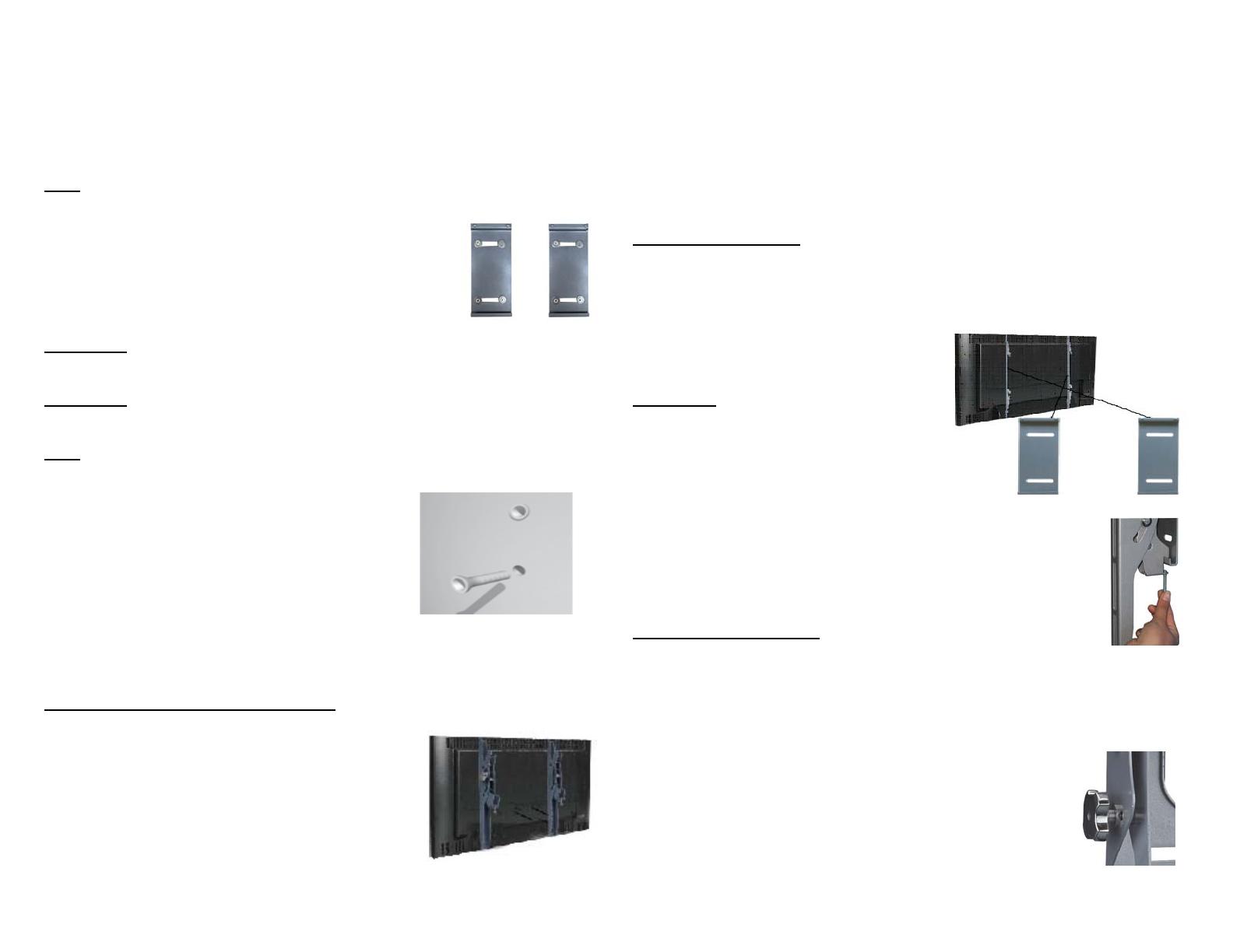
Endgültige Installation
Hängen Sie die Tragearme in das TV-Gerät ein, indem Sie die Löcher an den
Tragearmen mit den mit Schraubenwindungen versehenen Löchern an der
Rückseite des TV-Geräts in Übereinstimmung bringen, die Schrauben
hineinstecken und dann im Uhrzeigersinn festziehen, bis sie vollständig
hineingeschraubt sind.
1. Verwenden Sie einen
Sternschraubenzieher.
ACHTUNG: Für diese Fase der Montage
sind zwei Personen notwendig.
2. Zur endgültigen Montage des
LCD/Plasma Bildschirms hängen Sie
vorsichtig die am Gerät angebrachten
Tragearme in die obere und untere
Schiene der Wandplatten.
3. Ein weiteres Merkmal der Wandhalterung ist die
Sicherheitsschraube, die es unmöglich macht, das TV-Gerät
von der horizontalen Stange abzumontieren. Es genügt, die
Schrauben unterhalb der Tragearme des TV-Geräts fest
anzuziehen.
Funktion und Einstellung
Sie können die Neigung des Bildschirms regulieren, indem Sie die Schrauben
links und rechts an den Tragearmen des TV-Geräts benutzen.
1. Drehen Sie Schrauben gegen den Uhrzeigersinn, um die Stange der
Halterung zu lockern.
2. Um einen Neigungswinkel nach oben zu erreichen, drücken Sie auf die
obere Seite der Halterung und bringen Sie die Halterung in
die von Ihnen gewünschte Position, drehen Sie dann die
Schraube leicht zu. Um das Gerät nach vorne zu neigen,
drücken Sie auf die untere Seite der Halterung, bringen Sie
das Gerät in die von Ihnen gewünschte Position und
drehen Sie dann die Schraube leicht zu.
3. Wenn Sie die Halterung Ihren Bedürfnissen entsprechend
eingestellt haben, drehen Sie die Schrauben an den Tragearmen im
Uhrzeigersinn wieder fest zu.
  • Page 1 1
  • Page 2 2
  • Page 3 3
  • Page 4 4
  • Page 5 5
  • Page 6 6
  • Page 7 7
  • Page 8 8
  • Page 9 9
  • Page 10 10
  • Page 11 11
  • Page 12 12

VISA VE-S42T Owner's manual

Category
Flat panel wall mounts
Type
Owner's manual
This manual is also suitable for

Ask a question and I''ll find the answer in the document

Finding information in a document is now easier with AI