Page is loading ...

IINNVVEERRSSIIOONN
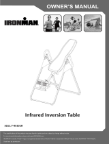
TTAABBLLEE
OWNER’S MANUAL
MODEL#75118
2011, Aug.
CAUTION: Weight on this product should not exceed 136kgs (300lbs).
CAUTION: Exercise of a strenuous nature, as is customarily done on this equipment, should not be undertaken
without first consulting a physician. No specific health claims are made or implied as they relate to the
equipment. Measurements made by the equipment are believed to be accurate, but only the measurements of
your physician should be relied upon.
IMPORTANT:
Read all instructions carefully before using this product. Retain this owner's manual for future reference.
Instructions for assembly, including correct fitting of guards and other device, and warnings about the likely
injuries to young children if exercise equipments are operated in their vicinity without properly fitted guards.
Product may vary slightly from picture.

TABLE OF
CONTENTS
ONE YEAR
LIMITED
WARRANTY
WARNING
Warranty
Warning
Safety Precautions
Overview Drawing
Parts List
Hardware Packing List
Assembly Instructions
Safety Operating
Instructions
Operation and Adjustments
Warm Up and Cool
Down Routine
LifeGear Inc. warrants to the
original purchaser that this
product is free from defects in
material and workmanship when
used for the purpose intended,
under the conditions that it has
been installed and operated in
accordance with LifeGear’s
Owner’s Manual. LifeGear’s
obligation under this warranty is
limited to replacing or repairing,
free of charge, any parts which
may prove to be defective under
normal home use. This warranty
does not include any damage
caused by improper operation,
misuse or commercial
application.
From the date of purchase, the
frame is warranted to be free
from defects for 1 (one) year.
This warranty is offered only to
the original owner and is not
transferable. Proof of purchase
is required.
NOTE: Maximum Weight
Capacity for this product is
300lbs/136kgs.
Transport and Storage:
Humidity Between : 10% - 80%
Temperature Between : -20 c - 60 c
WARNING
Before using this product,
please consult your personal
physician for a complete
physical examination.
Frequent and strenuous
exercise should be approved
by your doctor. If any
discomfort should result from
your use of this product, stop
exercising and consult your
doctor. Proper usage of this
product is essential. Please
read your manual carefully
before exercising.
Please keep all children away
from the equipment during
use and when equipment is
unattended.
Always wear appropriate
clothing, including athletic
shoes when exercising. Do not
wear loose clothing that could
become caught during
exercise.
Make sure that all bolts and
nuts are tightened when
equipment is in use. Periodic
maintenance is required on all
exercise equipment in order to
keep it in good condition.
1

SAFETY PRECAUTIONS
This inversion table was designed and built for optimum safety. However, certain precautions apply
whenever you operate the exercise equipment. Be sure to read the entire manual before assembling and
operating this equipment. Also, please note the following safety instructions:
1. Consult your physician or other health care professionals before using the inversion table.
2. Always wear proper exercise apparel when using the equipment.
3. If any time you feel faint, light-headed or dizziness while operating the equipment, stop exercise
immediately. You should also stop exercising if you are experiencing pain or pressure.
4. Keep children and pets away from the equipment while in use.
5. Only one person should use the equipment at a time.
6. Make sure your equipment is correctly assembled before you use it. Be sure all screws, nuts, and bolts
are tightened prior to use.
7. Do not operate this or any exercise equipment if it is damaged.
8. Watch your body: come up slowly, dizziness after a session means you came up too fast. Wait a while
after eating before using the inversion table. If you get nauseous, come up as soon as you feel queasy.
9. Always use this equipment on a clear and level surface. Do not use outdoors or near water.
10. Keep hands and feet away from any moving parts. Do not insert any object into any openings.
11. Keep loose clothes, jewelry away from moving parts.
12. WARNING: ALWAYS HOLD ON TO THE SAFETY HANDLES AND GO BACK SLOWLY WHEN
INVERTING. FAILURE TO COMPLY COULD RESULT IN SERIOUS BODILY INJURY.
WARNING: Before using this equipment you should consult with your personal
physician to see if inversion equipment is appropriate for you. Do not use this
equipment without your physician's approval. Do not use this equipment if you have
any of the following conditions or ailments:
Extreme obesity
Glaucoma, retinal detachment or conjunctivitis
Pregnancy
Spinal injury, Cerebral Sclerosis, or acutely swollen joints
Middle ear infection
High blood pressure, Hypertension, Recent stroke or Transient ischemic attack
Heart or circulatory disorders for which you are being treated
Hiatus hernia or Ventral hernia
Bone weaknesses including Osteoporosis, Unhealed fractures, Modularly pins, or Surgically
implanted orthopedic supports.
Use of anti-coagulants including Aspirin in high doses.
2

SAFETY PRECAUTIONS
3

OVERVIEW DRAWING
4
ˆˆ
˄˅
˅ˊ
˄ˈ
˄ˆ
ˆˌ
˅˅
˄ˌ
ˆ˄
˅˃
˅˅
˅ˈ
˄˄
˄ˈ
˄ˉ
˅ˊ
˄ˆ
ˌ
ˊ
˄ˉ
˄ˆ
˄ˈ
˅ˇ
˅ˆ
ˇ˃
ˆ˄
ˇ˅
˅ˈ
˅ˈ
˅ˊ
˄ˉ
˄˄
ˆ˄
ˊ
˄ˉ
ˆ
˄ˊ
˅ˈ
˄ˈ
ˉ
˅˄
˄ˆ
˄ˆ
ˇˆ
˅˄
˄ˈ
˄ˆ
˅
8L
˄ˆ
ˇˆ
ˆˋ
˅ˌ
ˆ˄
˄ˈ
ˆ˅
˅ˉ
ˆˋ
˄ˆ
ˆ˃
˄ˌ
˅ˌ
˄ˇ
ˆˊ
˄ˋ
˅ˋ
ˇˊ
ˈ
ˇˉ
ˆˉ
ˆˈ
ˇ
ˇ˄
ˇ˄
ˇˈ
˄˃
˄ˆ
˄ˉ
˄ˈ
˄ˆ
˄˅
ˆˇ
˄ˉ
˄˅
˅ˊ
˄˅
˅ˊ
8R
ˇˇ
˅ˊ
ˊ
ˊ
˄
˅ˊ
ˆˉ
ˈ
ˇˋ
ˇˋ
ˇˌ
ˇˌ

5
PARTS LIST
Part # Description Quantity Part # Description Quantity
1 Front U-Frame 1
2 Rear U-Frame 1
3 Adjustable Boom 1
4 Bed Frame 1
5 Pivot Arm 2
6 Adjustable lnstep Frame 1
7 Steel Heel Holder Bracket 4
8R Right Folding Arm 1
8L Left Folding Arm 1
9 Rod 1
10 Bolt M8x23 2
11 Hex Head Bolt M6x47 2
12 Phillips Screw M6x30 4
13 Washer Ø 20xØ 8.5x1.5 16
14 Round Plate 1
15 Lock Nut M8 8
16 Lock Nut M6 6
17 Small Spring Knob 1
18 Large Spring Knob 1
19 Safety Hook 2
20 Rubber Pad 1
21 Oval End Cap 2
22 Foot Bar End Cap 2
23 Spring 1
24 Square End Cap 1
25 Round End Cap 4
26 Lower Bed Frame Bushing 2
27 Washer Ø 16xØ 6.5x1.0 8
28 Upper Bed Frame Bushing 1
29 Handlebar 2
30 Knob 1
31 Rubber Heel Holder 4
32 Nylon Strap 1
33 Loop Strap 1
34 Strap Lock 1
35 Nylon Bed 1
36 Foam Grip 2
37 Protective Cover 2
38 Hex Head Bolt M8x23 2
39 Foot Bar 1
40 Hex Head Bolt M8x50 2
41 Square End Cap 2
42 Spring Latch 1
43 Hex Head Bolt M8x38 2
44 Height Scale 1
45 Plastic Bushing 1
46 Pad 1
47 Double Sided Tape 1
48 Nut Cap Ø 27xØ 13.5 2
49 Pivot Arm Ring 2
* Some of these parts have already been
assembled for you on the table. Please only
use the following list if you need to purchase
additional parts.

HARDWARE PACKING LIST
6
Part # Description Quantity
11 Hex Head Bolt M6x47 ----------------------------------------------------------------------------------------2
13 Washer Ø 20xØ 8.5x1.5 --------------------------------------------------------------------------------------12
15 Lock Nut M8 ------------------------------------------------------------------------------------------------------6
16 Lock Nut M6 ------------------------------------------------------------------------------------------------------2
27 Washer Ø 16xØ 6.5x1.0 ----------------------------------------------------------------------------------------4
38 Hex Head Bolt M8x23 ----------------------------------------------------------------------------------------2
40 Hex Head Bolt M8x50 ----------------------------------------------------------------------------------------2
41 Square End Cap -------------------------------------------------------------------------------------------------- 1
43 Hex Head Bolt M8x38 ----------------------------------------------------------------------------------------2
48 Nut Cap Ø 27xØ 13.5 ------------------------------------------------------------------------------------------2
49 Pivot Arm Ring --------------------------------------------------------------------------------------------------2
NOTE: The parts described above are all the parts you need to assemble this inversion table.
Before you start to assemble, please check the hardware packing to make sure they are
included.
All the other parts described in page 5 parts list are pre-assembled in the factory.
ASSEMBLY
Set all parts in a clear area on the floor and remove the packing materials. Refer to the part lists for help
to identify the parts. Follow the steps to assemble the inversion table.
Double open wrench M12x14 (2PCS)

ASSEMBLY INSTRUCTIONS
STEP 1:
Stand up the base of the machine by separating the u-frames. Pull the Front and Rear U-Frames
(1, 2) as far apart from each others as possible. Then push down on the middle of the Left and
Right Folding Arms (8L, 8R) until they are fully locked down.
7
The product is weighted more than 20 kg and should be
assembled and moved by two or more people.
1
2
8R
8L

STEP 2:
Install two Ø 27xØ 13.5 Nut Caps (48) onto M8 Lock Nuts (15). Slide one Protective Cover (37) on to
each side of the base as shown, and pull down on the Protective Covers (37) until the bottom of
the covers are slightly lower than the Left and Right Folding Arms (8L, 8R). Use the velcro straps
on the bottom of the Protective Covers (37) to secure the covers to the Left and Right Folding
Arms (8L, 8R). When the covers are assembled correctly, the Left and Right Folding Arms (8L, 8R)
should be fully covered by the Protective Covers (37).
8
37
2
1
INVERSION
T
ABLE
48
15
48

STEP 3:
Slide the bottom of the Pivot Arms (5) into the brackets that located at each side of the Bed Frame
(4), align to the desired hole on the arm with the peg on the bracket. Insert the peg into the hole
to lock the Pivot Arms (5) in place. It is recommended that you use the bottom hole on the Pivot
Arms (5) until you become more familiar with the equipment.
STEP 4:
Install the Pivot Arm Rings (49) onto the Pivot Arms (5). Mount the Bed Frame (4) to the Rear
U-Frame (2) by inserting the ends of the Pivot Arms (5) into the channels on the plates. The
slotted portion of the rollers on the end of the Pivot Arms (5) should be inserted into the channels
on the plates.
9
4
5
2
5
5
49
49
5
AB
49

STEP 5:
Slide the Rod (9) through the large round hole on the side of the Adjustable Boom (3), and secure
the Rod (9) on the Adjustable Boom (3) with one M6x47 Hex Head Bolt (11), one M6 Lock Nut (16),
and two Ø 16xØ 6.5x1.0 Washers (27). Slide one Steel Heel Holder Bracket (7) and one Rubber Heel
Holder (31) onto one end of the Rod (9) until the lock tooth is wedged into the slot in the Rod (9) as
shown in small figure. Use the same procedure to attach the other Steel Heel Holder Bracket (7) and
Rubber Heel Holder (31) onto the other end of the Rod (9).
Note: Make sure the lock teeth are wedged into the slots in the Rod (9) to lock the Steel Heel Holder
Brackets (7) and Rubber Heel Holders (31) in place before use.
STEP 6:
Slide the Foot Bar (39) into the bottom of the Adjustable Boom (3) and align two of the holes on
the Foot Bar (39) with two holes on the Adjustable Boom (3). Secure the Foot Bar (39) in place
using two M8x50 Hex Head Bolts (40), two M8 Lock Nuts (15), and four Ø 20xØ 8.5x1.5 Washers (13).
10
16
27
7
31
11
9
31
7
27
3
39
40
13
13
15
3

11
STEP 7:
Attach the Adjustable Instep Frame (6) to the Adjustable Boom (3) by inserting the Adjustable
Instep Frame (6) into the square bracket on the boom. Slide the Adjustable Instep Frame (6)
completely into the square bracket, insert the M6x47 Hex Head Bolt (11) with a Ø 16xØ 6.5x1.0
Washer (27) halfway through the square bracket, slide the M6x47 Hex Head Bolt (11) through the
ring at the bottom of the Spring (23), slide the M6x47 Hex Head Bolt (11) through the rest of the
square bracket, and secure at the other end with a Ø 16xØ 6.5x1.0 Washer (27) and M6 Lock Nut
(16). Attach the Square End Cap (41) onto the back of square bracket of Adjustable Boom (3).
Note: To slide the Adjustable Instep Frame (6) into the square frame, you must first pull out the
Small Spring Knob (17).
27
27
27
27
41
41
16
16
17
17
27
27
23
23
6
3
23
23
11
11
27
27
11
11
6
16
16

STEP 8:
Pull out the Large Spring Knob (18), and slide the Adjustable Boom (3) into the square bracket on
the bottom of the Bed Frame (4) as shown. Slide the Adjustable Boom (3) upward until the desired
height on the Height Scale (44) is just below the bracket on the bed frame. Lock the Adjustable
Boom (3) in place by releasing the Large Spring Knob (18) and sliding the Adjustable Boom (3) up
or down slightly until the Large Spring Knob (18) "pops" down into the locked position. For added
safety, secured the Knob (30) into the back side of the bracket on the Bed Frame (4).
12
1
0
1
7
8
1
1
1
8
0
1
2
1
8
3
18
5
1
3
1
4
1
8
8
1
9
0
1
5
1
6
1
9
3
17
1
95
1
8
1
9
8
1
9
2
0
0
2
0
2
0
3
2
1
2
0
5
2
2
2
0
8
2
3
2
1
0
2
0
3
2
4
2
0
5
2
5
4
3
30
18
44

13
STEP 9:
Attach the top end of Handlebar (29) onto the Rear U-Frame (2) and Pivot Arm Ring (49) with one
M8x 23 Hex Head Bolt (38), one M8 Lock Nut (15), and two Ø 20xØ 8.5x1.5 Washers (13). Attach the
bottom end of the Handlebar (29) onto the Rear U-Frame (2) with one M8x38 Hex Head Bolt (43),
one M8 Lock Nut (15), and two Ø 20xØ 8.5x1.5 Washers (13). Repeat above same steps to attach the
other Handlebar (29) onto the Rear U-Frame (2) and Pivot Arm Ring (49).
13
15
29
43
13
13
15
38
13
2
49

STEP 10:
Attach the Nylon Strap (32) to the Strap Lock (34) by inserting the end of the Nylon Strap (32) up
through the bottom of the Strap Lock (34), loop the Nylon Strap (32) over the Pre-assembled Loop
Strap (33) and down through the Strap Lock (34). Now, loop the strap back over itself, and insert
back through the Strap Lock (34), and pull tight to secure.
STEP 11:
Attach the Nylon and Loop Straps (32, 33) to the Inversion Table by hooking the end of the Nylon
Strap (32) to the pre-assembled loop on the back of the Bed Frame (4) as shown. Now hook the
other end of Loop Strap (33) to the other Pre-assembled loop on the Front U-Frame (1) as shown.
14
19 3433 32 19
19
33
34
32
19
34
32
1
4
19
19

SAFETY OPERATING INSTRUCTIONS
15
Pivot arm is NOT aligned correctly.
The pivot arm is not inserted all the
way into the curved slot.
Make sure the pivot arm is inserted all the
way into the slot. Pivot arm is aligned correctly
when the groove sits directly on the curved
slot and the pivot arm is able to rotate freely.
WARNING: Please make sure both pivot arms are in the same hole to prevent serious
injury from occurring.
Incorrect
Correct

OPERATION AND ADJUSTMENTS
16
ADJUSTING THE STRAP
For added safety, a nylon strap has been included to restrict the degree of inversion. This strap
can be adjusted to different lengths to allow for a greater or lesser degree of inversion. To
lengthen the Nylon Strap (32) feed the top end of Nylon Strap (32) into the strap lock, and pull on
the lower end of the strap. To shorten the length feed the bottom end of Nylon Strap (32) into the
strap lock, and pull on the top end.
ADJUSTING THE BOOM
The Adjustable Boom (3) can be moved to a variety of different positions, in order to
accommodate the height of the person on the inversion table. To adjust the boom loosen the
Knob (30), pull out the Large Spring Knob (18), and slide the boom up or down until the desired
height on the Height Scale (44) is positioned just below the Square Bushing (26). When the boom
is in the desired position, simply release the Large Spring Knob (18), slide the boom slightly up or
down until the Large Spring Knob (18) locks into place, and tighten the Knob (30).
4
18
30
3
44
32
32
SHORTEN
THE STRAP
LENGTHEN

17
PIVOT ARMS
The Pivot Arms (5) can be adjusted to allow for a greater or lesser degree of inversion. To adjust
the Pivot Arms (5) simply pull out on them until the post is out of the hole, slide them up or down
to the desired hole, push in until the post goes through the desired hole. The bottom hole
provides the least amount of inversion, while the top hole provides the greatest amount. It is
recommended that beginners use the bottom hole until they are familiar with the inversion table.
NOTE: Both Pivot Arms (5) must be adjusted to the same hole. Trying to adjust the Pivot Arms (5)
on two different positions could cause damage to the inversion table, or injury to the user.
THE HANDLEBARS
For added convenience and safety, a set of Handlebars (29) has been added to the inversion table.
These Handlebars (29) are located at the top of the Rear U-Frame (2). The Handlebars (29) are
there to help you return to the upright position from any degree of inversion. If you wish to
return to the upright position, and the bed is moving too slowly, or not moving at all, simply grab
the Handlebars (29) and pull on them until you return to the upright position.
NOTE: The inversion table should always return to the upright position when you move your
hands below your waist. If it does not, the inversion table is probably not adjusted correctly to
your height.
4
5

18
ADJUSTING THE ANGLE HOLDER
Pull up on the Small Spring Knob (17), slide the Adjustable Instep Frame (6) upward. Stand on the
Foot Bar (39) located at the bottom of the Adjustable Boom (3). Pull up on the Small Spring Knob
(17), allow the Adjustable Instep Frame (6) to slide back into the Adjustable Boom (3). Push in
slightly on the Adjustable Instep Frame (6) until the Rubber Heel Holders (31) are around your
ankles. Release the Small Spring Knob (17) and adjust the Adjustable Instep Frame (6) slightly
until the Small Spring Knob (17) locks into place.
GENERAL PRECAUTIONS
1. Make sure that the Pivot Arms (5) are locks on the lowest hole for the first few attempts.
2. It is recommended that someone be with you while you are using this inversion table for the
first few times.
3. Make sure that the Rubber Heel Holders (31) are holding your feet securely.
4. Make sure that the Adjustable Boom (3) is properly set to your height.
5. Make sure that the Adjustable Boom (3) is held securely by both the Large Spring Knob (18) and
the Knob (30).
6. Make sure that there is enough room for the bed to rotate completely.
17
6
3
31

19
BALANCING THE INVERSION TABLE
The inversion table is like a very sensitively balanced fulcrum. It responds to very slight changes
in weight distribution. So, it is very important to make sure that the height is adjusted properly.
To do this, mount the inversion table, lock your ankles into the rubber heel holders, and lie back
with your hands at your sides. Slowly place you hands across you chest. While in this position,
your head should still be above our feet. If your feet are above your head, dismount and adjust
the height again.
USING THE INVERSION TABLE
1. Start by lying fully back on the bed with your hands at your side, or resting on your thighs.
2. Keeping your hands close to your body begin to raise your arms slowly allowing the table to
rotate backward. Stop, or lower your arms to control the downward rotation of the table.
3. Raise your arms until they are over your head. At this point, the inversion table will be as far
back as it can go.
4. As you get more comfortable with the use, rock the bed slowly by moving your arms up and
down slowly.
5. It is recommended that the inversion table be used for five or ten minutes each morning, and
again each evening.
6. Return to the upright position by slowly moving your hands back down to your thighs.
/