Page is loading ...

5/8/14, 5:55 AMInstallation Procedures | ClarkDietrich Building Systems
Page 1 of 5http://www.clarkdietrich.com/products/shaftwall/clarkdietrich-shaftwall-systems/technical-content/installation-procedures
Shaftwall › ClarkDietrich Shaftwall Systems › Technical Content
INSTALLATION PROCEDURES
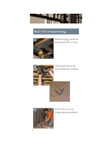
Helpful Hints
In structural steel-frame construction, install perimeter J-Tabbed Track sections before applying spray-on fireproofing.
Pre-cut C-T studs 3/4" less than the opening’s height between top and bottom J-Tabbed Track.
Items to be anchored to the wall (cabinets, sinks, handrails, etc.) should be fastened to steel plates secured behind or
between layers of 1/2" gypsum.
Use Type-S screws for 25-gauge steel framing. Use type S-12 screws for 20-gauge (or heavier) steel framing.
It is important that the job engineer approve the type, size, and maximum spacing of track fasteners to meet the design
load requirements.
Limitations of Use
Shaftwall assemblies are designed as non-load-bearing partitions only.
Do not install in areas which will be adjacent to occupancies of unusually high moisture conditions.
Provide control joints so that maximum length of continuous partition is 30 feet. Wherever possible, the partition
control joints should coincide with those in the building structure.
Elevator door frames should be supported independently of the shaftwall. However, interfacing of elevator frame to
shaftwall system may require attachment with jamb clips and/or grouting.
Where penetrations occur in the partitions, additional reinforcement at corners may be necessary to distribute stresses
if control joints are not used and if excessive loads need to be supported.
To prevent air movement and resulting whistling, the partition perimeters, as well as all penetrations, should be
effectively sealed with a non-hardening sealant.
Finishing of all joints in face layers should be done within temperature limitations of the specific joint treatment used.
Not recommended for use as an unlined HVAC supply shaft or duct.
Hollow cavities must be fire stopped at each floor.
Installation Procedures - Vertical Shaftwalls
1. Layout per construction drawings. Secure J-Tabbed Track as perimeter framing and plumb to ceiling, floor and sides.
Attached with suitable fasteners, spaced not more than 24" o.c. Apply a bead of non-hardening, flexible sealant to the
perimeter.
2
. Pre-plan the stud layout 24" o.c. and adjust the spacing at either end so the end studs will not fall closer than 12" from
the end.
3
. Erect the first 1" Shaftliner panel, cut 3/4"-1" less than the total height of the framed section. Plumb the panel against
the web of the J-Tabbed Track and bend out tabs in J-Tabbed Track to secure panels in place.
4
. Insert C-T Stud, cut 3/4" less than overall height, into the top and bottom J-Tabbed Tracks and fit tightly over previously

5/8/14, 5:55 AMInstallation Procedures | ClarkDietrich Building Systems
Page 2 of 5http://www.clarkdietrich.com/products/shaftwall/clarkdietrich-shaftwall-systems/technical-content/installation-procedures
installed 1" panel. Allow equal clearance between top and bottom J-Tabbed Track.
5. Install the next 1" Shaftliner inside the J-Tabbed Track and within the tabs of the C-T stud.
6. Progressively install succeeding studs and panels as described above until the wall section is enclosed. The final panel
section may be secured with tabs from the J-Tabbed Track at 12" o.c.
7. Where wall heights exceed the standard or available length of Shaftliner panels, the panels may be cut and stacked with
joints occurring within the top or bottom third points of the wall. Joints of adjacent panels should be alternately
staggered to prevent a continuous horizontal joint. Gypsum panels must engage a minimum of 2 tabs.
8. CT Studs cannot be spliced. They must be installed full height, one piece.
9. For doors, ducts or other large penetrations or openings, install J-Tabbed Track as perimeter framing. Use 20-gauge
track with a 3" back leg for elevator doors and block cavity with 12" wide gypsum filler strips for doors exceeding 7'-0"
height.
Location of Gypsum Board Joints
1. Shaftliner panels may be abutted (spliced or stacked) within the cavity as shown in the drawing above. The shorter panel
should be at least two feet long or of sufficient length to engage two stud tabs on each panel edge. NOTE: In addition,
some local codes may also require that these splices be back-blocked with a 12" x 24" piece of gypsum even though the
tests were preformed with these joints unblocked. Also , back blocking may be done with the CT Stud of proper length
and placed horizontal. Please check with your local jurisdiction.
2. For the shaftwall system, finished one side, install the first layer of 1/2" fire code board horizontally with 1" Type-S screws
spaced 24" o.c. and 3" from all edges. The horizontal joints must be offset from any splice joints in the shaftliner panels
by at least 12".
3. The face layer, also fire code board, installed parallel to framing with 1-5/8" Type-S screws spaced 12" o.c. at all framing
members maintaining a 6" edge distance. All edge and end joints should be offset from the base layer by 24"
4. For the stairwall system, finished both sides, each side must be installed vertically with 1" Type-S Screws spaced 12" o.c.
maintaining a 3" distance from edge. Offset edges and ends on opposite sides 24" o.c.

5/8/14, 5:55 AMInstallation Procedures | ClarkDietrich Building Systems
Page 3 of 5http://www.clarkdietrich.com/products/shaftwall/clarkdietrich-shaftwall-systems/technical-content/installation-procedures
5. Caulk all perimeter edges and abutments with dissimilar materials, and penetrations in the facing layers with a non-
hardening flexible sealant.
6. All joints on face layers are to be taped and finished and fastener heads finished with joint compounds meeting ASTM
C475 standard specification.
Installation Procedures - Horizontal Shaftwalls for Corridor Ceilings and Stairway Soffits
Two Hour Horizontal Shaft Wall Assembly Instructions – See Figures 8 - 9 below
1. Horizontal ceiling applications are not designed for any live load, mechanical equipment, or for any storage load.
2. Maximum spans are as shown in Table 2.
3. The corridor ceiling or stair soffit horizontal assembly is constructed from the floor.
4. J-track (Item ) is first secured to all corridor walls or stair stringer framing around the perimeter of the ceiling or stair
soffit to be protected.
5. The J-track (Item ) will be at a minimum:
a. 33-mil, 0.0346-in (20-ga) thickness for 25-ga and 20-ga CT-studs. (Item )
b. 43-mil, 0.0451-in (18-ga) thickness for 18-ga CT-studs. (Item )
6. The J-track (Item ) is positioned with the shorter 1-in long leg of the track facing the floor.
a. Fasteners are placed through the web of the J-track to the supporting structure
b. Mechanical fasteners shall be spaced a maximum of 24-in on-center along the length of the J-track to the
supporting structure.
c. The track to perimeter wall connection (Item ) shall be detailed by the designer to provide a minimum of 200 lbs
of shear capacity for every CT-stud location.
7. 1-inch thick x 24-inches-wide gypsum shaft liner panels (Item ) are inserted in the J-runners (Item ) towards the
ceiling (2-in leg of the J-runner).
a. Measure the overall dimensions of the opening and determine if the first 1-in shaft liner installed should be cut
lengthwise so that the final shaft liner panel is not less than 8-in in width.
b. The first liner panel will be secured to the J-track by using #6 x 1-5/8-in drywall screws 12-in on-center and at each
end through the longer leg of the J-track.
8. CT-stud (Item ) of the required depth and thickness will positioned so that it secures the free edge of the first shaft
liner panel within the “T” portion of the CT-stud.
9. Do not splice CT-studs. Use only full length pieces of the proper length.
10. Both ends of the CT-stud (Item ) will be secured to both flanges of the J-runner using a minimum ½” long #8 pan-
head screw (Item ).
11. The sequence of alternating placement of shaft liner panels (Item ) and CT-studs (Item ) will continue with each
CT-stud engaging the long edges of the 1-in shaft liner panels.
12. The end of each 1-in shaft liner panel within the perimeter J-runner track is fastened to the J-runner track flange with
three #6 x 1 5/8” Type S screws (12-in on-center).
13. Liner panels may be cut; butt the factory ends of the liner panels. The butt joints shall occur within the outermost one
third points of the span. Joints in adjacent liner panels shall be alternately staggered to prevent a continuous joint.
14. Secure the last liner panel to the tabbed J-runner by using #6 x 1-5/8-in drywall screws 12-in on-center and at each end
through the longer leg of the J-track.
15. For a two-hour assembly two layers of 1/2" Type C or 5/8" Type X gypsum board (Item ) should be installed at right

5/8/14, 5:55 AMInstallation Procedures | ClarkDietrich Building Systems
Page 4 of 5http://www.clarkdietrich.com/products/shaftwall/clarkdietrich-shaftwall-systems/technical-content/installation-procedures
angles to the framing members. Install the inner layer with #6 (Item ) x 1" Type S drywall screws, 24" o.c., starting 3"
maximum from the ends of the C-T studs. Butt joint of adjacent panels should be centered on a stud flange. Install the
outer layer of 1/2" Type C or 5/8" Type X gypsum board with #6 (Item ) x 1-5/8” Type S drywall screws, 12" o.c. in the
field and at the perimeter. Offset the board joints a minimum of one stud spacing (24”) between layers.
16. Caulk the perimeter edges and abutments with dissimilar materials and any penetrations with a non-hardening flexible
sealant (Item ).
17. All joints on the outer layer shall be taped and finished and fastener heads finished with joint compounds meeting ASTM
C474.
Figure 8 & 9 descriptions
1. J-Track
2. Corridor Side Gypsum
3. C-T Stud (full span length)- See Table 2 above.
4. Liner Panel on top side. One seam only per stud bay allowed.
5. Fastener thru J-Track into wall at 24"o.c. maximum spacing.
a. Fastener must provide a minimum of 200 Lbs. of shear value per C-T Stud
6. Framing fastener thru J-Track top & bottom legs into C-T Stud.
7. Gypsum fasteners thru gypsum into framing.
8. Approved Fire-Resistance joint sealant system.

5/8/14, 5:55 AMInstallation Procedures | ClarkDietrich Building Systems
Page 5 of 5http://www.clarkdietrich.com/products/shaftwall/clarkdietrich-shaftwall-systems/technical-content/installation-procedures
© 2014 Clarkwestern Dietrich Building Systems LLC
Site Search Products Sitemap Locations Contact Us Patents & Trademarks Terms & Conditions
View mobile site • Web development by arsnova.cc, Indianapolis
The data contained in this site is intended to be informative and accurate.
However, it is to be used as a technical guideline only and does not replace the judgments and designs of a qualified architect
and/or engineer. ClarkDietrich Building Systems reserves the right to change data, tables, or charts shown herein without
notification.
Contact ClarkDietrich Technical Services at 888-437-3244 for any questions about ClarkDietrich's Shaftwall
Systems.
/