Page is loading ...

1
HI 4221 & HI 4222
pH/mV/ISE/Temperature
Bench Meters
Instruction Manual
www.hannainst.com

2
HI 4221 and HI 4222 are warranted for two years against defects in workmanship and materials when used
for their intended purpose and maintained according to instructions. Electrodes and probes are guaranteed for
six months. This warranty is limited to repair or replacement free of charge.
Damage due to accidents, misuse, tampering or lack of prescribed maintenance is not covered.
If service is required, contact the dealer from whom you purchased the instrument. If under warranty, report
the model number, date of purchase, serial number and the nature of the failure. If the repair is not covered
by the warranty, you will be notified of the charges incurred. If the instrument is to be returned to Hanna
Instruments, first obtain a Returned Goods Authorization number from the Technical Service Department and
then send it with shipping costs prepaid. When shipping any instrument, make sure it is properly packed for
complete protection.
To validate your warranty, fill out and return the enclosed warranty card within 14 days from the date of
purchase.
Dear Customer,
Thank you for choosing a Hanna Instruments product. This manual will provide you with the necessary
information for correct use of the instrument.
Please read this instruction manual carefully before using the instrument.
If you need additional technical information, do not hesitate to e-mail us at [email protected] or see the
back side of this manual for our worldwide sales and technical service contacts.
These instruments are in compliance with
directives.
WARRANTYWARRANTY
WARRANTYWARRANTY
WARRANTY

3
TABLE OF CONTENTSTABLE OF CONTENTS
TABLE OF CONTENTSTABLE OF CONTENTS
TABLE OF CONTENTS
WARRANTY ...................................................................................................................................... 2
PRELIMINARY EXAMINATION .............................................................................................................. 4
GENERAL DESCRIPTION ...................................................................................................................... 4
FUNCTIONAL DESCRIPTION ................................................................................................................ 5
SPECIFICATIONS ................................................................................................................................ 8
OPERATIONAL GUIDE ....................................................................................................................... 9
DISPLAYING MODES ......................................................................................................................... 11
SYSTEM SETUP ............................................................................................................................... 14
pH SETUP ...................................................................................................................................... 20
mV SETUP ..................................................................................................................................... 32
ISE SETUP (HI 4222 only) .............................................................................................................. 33
pH CALIBRATION & MEASUREMENTS ................................................................................................. 39
mV & RELATIVE mV MEASUREMENTS ................................................................................................ 44
ISE CALIBRATION & MEASUREMENTS (HI 4222 only) ........................................................................ 46
LOGGING ....................................................................................................................................... 57
PC INTERFACE .................................................................................................................................... 62
pH BUFFER TEMPERATURE DEPENDENCE .......................................................................................... 63
ELECTRODE CONDITIONING & MAINTENANCE ..................................................................................... 64
TROUBLESHOOTING GUIDE .............................................................................................................. 66
TEMPERATURE CORRELATION FOR pH SENSITIVE GLASS ...................................................................... 67
ACCESSORIES .................................................................................................................................. 68

4
GENERAL DESCRIPTIONGENERAL DESCRIPTION
GENERAL DESCRIPTIONGENERAL DESCRIPTION
GENERAL DESCRIPTION
Remove the instrument from the packing material and examine it carefully to make sure that no damage has
occurred during shipping. If there is any damage, notify your dealer or the nearest Hanna Service Center.
The meters are supplied complete with:
• HI 1131B Glass-body Combination pH Electrode
• HI 7662-T Temperature probe
• pH 4.01 & 7.01 Buffer solutions, 20 mL each
• HI 700661 Cleaning Solution, 2 x 20 mL
• HI 7071S Electrolyte solution
• HI 76404N Electrode Holder
• 12Vdc Power Adapter
• Instruction Manual
HI 4221 and HI 4222 are supplied with 12 Vdc/230 Vac adapter.
HI 4221-01 and HI 4222-01 are supplied with 12 Vdc/115 Vac adapter.
Note: Save all packing material until you are sure that the instrument works properly. Any defective item
must be returned in the original packing with the supplied accessories.
PRELIMINARY EXAMINATIONPRELIMINARY EXAMINATION
PRELIMINARY EXAMINATIONPRELIMINARY EXAMINATION
PRELIMINARY EXAMINATION
HI 4221 and HI 4222 are professional bench meters with color graphic LCD for pH, ORP (Oxidation Reduction
Potential), ISE (HI 4222 only) and Temperature measurements with Calibration Check.
The display can be configured as a single channel or dual channel display (HI 4222 only) in various modes: Basic
information only, GLP information, Graph mode and Log History mode. Each channel can be configured as pH, mV,
Relative mV or ISE (HI 4222 only).
The main features of the instruments are:
• One (HI 4221), or two (HI 4222) input channels;
• Manual selection, automatic and semiautomatic pH calibration up to five points, with standard (1.68, 3.00,
4.01, 6.86, 7.01, 9.18, 10.01 and 12.45) and custom buffers (up to 5 custom buffers);
• Manual Selection and Custom Standard ISE calibration up to five points, with standard (0.1, 1, 10, 100,
1000 ppm) and custom solutions (up to 5 custom solutions), with or without temperature compensation;
• AutoHold feature to freeze first stable reading on the LCD;
• Two selectable alarm limits;
• Five selectable logging modes: Automatic logging with and without AutoHold feature, Manual logging with
or without AutoHold and AutoHold logging mode;
• Up to 100 logging lots;
• Selectable log interval and log sampling features for Automatic logging;
• GLP feature;
• Online and offline graph;
• User-friendly interface on large color graphic LCD (240x320 pixels);
• PC interface via RS232, and USB.

5
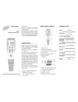
HI 4221 DESCRIPTION
FRONT PANEL
REAR PANEL
1) Liquid Crystal Display (LCD)
2) Main Keyboard
3) USB connector
4) ON/OFF switch
5) Power adapter socket
6) RS232 serial communication connector
7) Temperature probe socket
8) BNC electrode connector for pH/ORP measurements
9) Reference input socket
FUNCTIONAL DESCRIPTIONFUNCTIONAL DESCRIPTION
FUNCTIONAL DESCRIPTIONFUNCTIONAL DESCRIPTION
FUNCTIONAL DESCRIPTION

6
HI 4222 DESCRIPTION
FRONT PANEL
REAR PANEL
1) Liquid Crystal Display (LCD)
2) Main Keyboard
3) USB connector
4) ON/OFF switch
5) Power adapter socket
6) RS232 serial communication connector
7) Temperature probe socket (Channel 2)
8) BNC electrode connector for pH/ORP/ISE measurements (Channel 2)
9) Reference input socket (Channel 2)
10) Temperature probe socket (Channel 1)
11) BNC electrode connector for pH/ORP/ISE measurements (Channel 1)
12) Reference input socket (Channel 1)

7
KEYBOARD DESCRIPTION
FUNCTION KEYS
VIRTUAL KEYS
The upper row keys are assigned to the virtual keys placed on the bottom of the LCD, which allow you to
perform the displayed function, depending on the current menu (e.g.
,
and in
Measure
mode).
Note: All the virtual keys are assigned to the focused channel (HI 4222 only).
LCD GENERAL DESCRIPTION
To enter/exit calibration mode.
To select the desired measurement mode, pH, mV, Rel mV (or ISE – HI 4222 only).
To enter Setup (System, pH, mV or ISE) and to access Log Recall function.
To obtain general informations about the selected option/operation.

8
SPECIFICATIONSSPECIFICATIONS
SPECIFICATIONSSPECIFICATIONS
SPECIFICATIONS
1224IH2224IH
EGNAR
– Hp000.02ot000.2
± Vm0.0002
– 01*1
6–
01*99.9ot
01
.cnoc
– /Cº0.021ot0.02 – K51.393ot51.352/Fº0.842ot0.4
NOITULOSER
Hp100.0/Hp10.0/Hp1.0
Vm1.0
– .cnoc100.0/.cnoc10.0/.cnoc1.0/.cnoc1
K1.0/Fº1.0/Cº1.0
YCARUCCA
Fº86/Cº02@
± Hp1.0
± Hp10.0
± Hp200.0 ± DSL1
± Vm2.0 ± DSL1
–
± )snoitnelavonom(%5.0
± )snoitnelavid(%1
± /Cº2.0 ± /Fº4.0 ± K2.0
egnartesffoVmevitaleR ± Vm0.0002
noitarbilaCHp
elbaliavasreffubdradnats8,noitarbilactniop-evifotpU
,10.7,68.6,10.4,00.3,86.1(54.21,10.01,81.9,)sreffubmotsuc5dna
noitarbilaCESI –
,noitarbilactniop-evifotpU
elbaliavasnoitulosdradnatsdexif5
,tinutnemerusaemhcaerof
snoitulosmotsuc5dna
slennahctupnI1 2
noitasnepmocerutarepmeT
morfcitamotuArolaunaM
– /Cº0.021ot0.02 – K393ot352/Fº0.842ot0.4
edortcelEHpB1311IH
eborperutarepmeTT-2667IH
ecafretniCPBSUdna232SRdetalosi-otpo
ecnadepmitupnI01
21
smho
ylppusrewoPretpadacdV21
snoisnemiD)”7.3x1.9x3.6(mm49x132x061
thgieW)bl6.2(gK2.1
tnemnorivnE
K323–372/Fº221–23/Cº05–0
gnisnednoc-nonHR%59.xam
ytnarraWsraey2

9
POWER CONNECTION
Plug the 12 Vdc adapter into the power supply socket.
Notes: • These instruments use non volatile memory to retain the pH, Ion calibrations and all other
settings, even when unplugged.
• Make sure a fuse protects the main line.
ELECTRODE AND PROBE CONNECTIONS
For pH or ORP measurements connect a pH/ORP electrode with internal reference to the BNC connector
located on the rear panel of the instrument (for the desired channel – HI 4222 only).
For ISE measurements (HI 4222 only) connect, to the desired channel, an ISE electrode with internal
reference to the BNC connector located on the rear panel of the instrument.
For electrodes with a separate reference connect the electrode’s BNC to the BNC connector and the electrode’s
reference to the reference input socket.
For temperature measurements and automatic temperature compensation connect the temperature probe to the
appropriate socket (for the desired channel – HI 4222 only).
INSTRUMENT START UP
• Turn the instrument on from the power switch located on the rear panel of the instrument.
• Please wait until the instrument finishes the initialization process.
Note: It is normal for the loading process to take a few seconds. If the instrument doesn’t display the next
screen, restart the meter using the power switch. If the problem persists, contact your dealer.
OPERATIONAL GUIDEOPERATIONAL GUIDE
OPERATIONAL GUIDEOPERATIONAL GUIDE
OPERATIONAL GUIDE

10
CHANNEL SELECTION (HI 4222 only)
• Press
while in
Measure
mode to access channel
selection menu. Four available options will be displayed:
Channel 1, Channel 2, or multi-channel with the first or the
second channel focused. The “Choose Channel Configuration”
message is displayed in the Reminder messages area.
• Select the desired option by pressing the appropriate key:
,
, or . The instrument will enter in the
selected option
Measure
mode.

11
DISPLAYING MODESDISPLAYING MODES
DISPLAYING MODESDISPLAYING MODES
DISPLAYING MODES
For each measurement mode (pH, mV, Rel mV or Ion) the following display configurations are available:
Basic, Good Laboratory Practice (GLP), Graph and Log History.
Basic
Accessing this option, the measured value and its units are displayed on the LCD, along with the temperature
value, temperature compensation mode, and GLP data.
To choose the Basic displaying mode:
• Press
while in
Measure
mode. The “Choose Display Configuration” message will be displayed in
the Reminder messages area.
• Press
. The instrument will display the basic information for the selected measurement mode.
GLP
Accessing this option, detailed GLP data will be displayed on the LCD for
pH Measure
and
ISE Measure
modes
only: Last Calibration date and time, Offset and Slope values, Calibration Buffers/Standards and general
information regarding the buffers/standards: the calibration temperature, temperature compensation mode,
date and time. For
pH Measure
, the Electrode Condition is also displayed on the LCD in percent.
Note: If only a one-point pH calibration is performed or the current calibration does not include at least two consecutive
standard buffers of pH 4.01, 7.01 (6.86) and 10.01 (9.18) buffers, the Electrode Condition will be unknown.
To access the GLP displaying mode:
• Press
while in
Measure
mode. The “Choose Display Configuration” message will be displayed in
the Reminder messages area.
• Press . The instrument will display the detailed GLP data.

12
Graph
Accessing this option, the online graph with currently logged values (pH, mV, Rel mV, or ISE vs. Seconds) will
be displayed.
If there is no active log, the previously logged data for the selected parameter will be plotted.
Notes: • If no data were logged, the graph displaying mode will not be accessible.
• If no automatic log is saved, the offline graph will not be available.
To access the offline / online graph:
• Press
while in
Measure
/
Logging
mode. The “Choose Display Configuration” message will be
displayed in the Reminder messages area.
• Press
.

13
When the online graph is displayed:
•Use
and to move the graph along X (Time) axis.
• Press to access the zoom menu for Y axis. Use or for zooming Y (parameter) axis.
• Press
to return to the main menu.
When the offline graph is displayed:
• Use the arrow keys to move the graph along X (Time) and Y (parameter) axes.
• Press
to access the zoom menu for X and Y axes. Use , or / / /
to switch between the active zooming axes. Press or to zoom the selected axis.
Note: While in zoom graph menu the key is not accessible.
• Press
to return to the main menu.
Log History
Accessing this option, last logged records will be displayed on the LCD. The log history list also contains the appropriate
mV values, the logged temperature, the temperature compensation source, as well as the records time stamp.
Note: If no data were logged, the “Log History Empty” message will be displayed on the LCD.
To access the Log History displaying mode:
• Press
while in
Measure
mode. The “Choose Display Configuration” message will be displayed in
the Reminder messages area.
• Press . The instrument will display the log history regarding the selected
Measure
mode.
Notes: • When an alarm condition is active, all logged records will have an exclamation mark (!).
• If another
Measure
mode is selected, the Log History will reset.
• If the temperature unit is changed, all logged temperature values will be automatically displayed
in the new temperature unit.

14
SYSTEM SETUPSYSTEM SETUP
SYSTEM SETUPSYSTEM SETUP
SYSTEM SETUP
The System Setup menu allows the user to customize the user interface, consult the meter information, set the
external serial communication interface and to restore the manufacturer settings.
Accessing System Setup
• Press
while in
Measure
mode.
• Press
. The system setup options will be displayed on
the LCD.
To access a System Setup option:
• Use
or to highlight the desired option.
• Press
to access the selected option.
The following is a detailed description of the System Setup option
screen.
Beeper
This option allows the user to enable or disable the beeper. When the beeper is enabled, a specific beep will
be heard when the reading becomes stable, when an alarm condition is reached,
when pressing a key or if
a wrong key is pressed.
Stability Indicator
When the reading becomes stable, the instrument delivers a medium beep only if this option is ON, along with the
“Stable” indicator on the LCD.
Alarm
If this option is ON, a continuous double beep will be heard each time the set limits in
Measure
mode are
exceeded, along with the “Alarm” indicator on the LCD.
Key Pressed
If this option is ON, a short beep will be heard each time a valid key is pressed.
Wrong Key
If this option is ON, a long beep will be heard when an incorrect key is pressed.
To set the Beeper:
• Press while in
Measure
mode.
• Press
.

15
• Use
or to select the Beeper option.
• Press
and use or to highlight the
desired beeper status option you want to modify.
• Press
and use or to highlight the
desired option.
• Press
to confirm your selection and return to the Beeper
menu or press
to return to the Beeper menu without
changing.
Saving Confirmation
When enabling this option, a prompt will appear on the LCD alerting the user to save the modified values by
pressing
, exiting without saving by pressing or canceling the saving operation and return to the
editing mode by pressing
. If disabled, the modified values will be saved automatically.
To modify the Saving Confirmation option:
• Press
while in
Measure
mode.
• Press
.
• Use
or to select the Saving Confirmation option.
• Press
and use or to highlight the
desired Saving Confirmation option.
• Press
to confirm your selection or press
to
cancel operation.
GLP Data
This option allows the user to set general information which will appear in the log reports. The options are
available for both channels (HI 4222 only) and can have a max of 10 characters.
Operator ID
– this option allows you to edit the name of the operator.
Instrument ID
– this option allows you to edit an identification name/number for the instrument.
Company Name
– this option allows you to edit the company name.
Additional Info 1 & Additional Info 2
– for general purpose notations.

16
To set the GLP Data:
• Press
while in
Measure
mode.
• Press
.
• Use
or to select the GLP Data option.
• Press
and use or to highlight the
desired option.
• Press
to edit the desired information. The Text Editor menu
will be displayed on the LCD.
• Enter the desired information by accepting the highlighted character
which is added to the text bar, using
. The and
keys help the user select the desired character. It is also
possible to delete the last character by positioning the cursor on the
Backspace character (
) and pressing .
• Press
to return to the GLP Data options. If the Saving Confirmation is enabled, press to accept
the modified option,
to escape without saving or to return to the editing mode. Otherwise,
the modified options are saved automatically.
Date & Time
This option allows the user to set the current date & time and the format in which they appear. These parameters
will be displayed on the
Measure
screens and also when storing measured data.
Set Date and Time
This option allows you to set the current date (year/month/day) and time (hour/minute/second).
Notes: • Only years starting with 2000 are accepted.
• The time is set using the selected time format. For 12 Hour time format only, the AM/PM can also
be selected with
or .
Set Time Format
This option allows you to choose between 12 Hour (AM/PM) time format and 24 Hour time format from the
displayed pop-up menu.
Set Date Format
This option allows you to choose the desired date format from 6 available options: DD/MM/YYYY; MM/DD/YYYY;
YYYY/MM/DD; Mon DD, YYYY; DD-MM-YYYY and YYYY-Mon-DD.
To set the Date & Time:
• Press
while in
Measure
mode.
• Press
.

17
• Use
or to select the Date & Time option.
• Press
and use or to highlight the
desired option you want to modify.
• Press
to confirm your selection. Use /
to select next/previous entry to be edit. Press and use
or to set the desired value, then press
to save the modified value (for Set Date and Time option). For
the other two options press
to confirm your selection
and select one of the displayed options with
or .
• Press
to confirm your selection and return to the Date &
Time options.
• Press
to return to Date & Time options (for Set Date and Time option only). If the Saving Confirmation
is enabled, press
to accept the modified option, to escape without saving or to
return to the editing mode. Otherwise, the modified option is saved automatically.
Note: If the time is changed with more than one hour before last pH/ION calibration, a pop-up warning will
appear on the LCD, notifying the user that a date/time conflict has occured and some time-dependent
modes could work improperly (e.g.
Measure
, GLP, Log).
LCD Setup
This option allows the user to set the Contrast, the Backlight of the LCD and the Backlight Saver. The Contrast
parameter can be adjusted within 7 steps, while the Backlight parameter within 4 steps. The Backlight Saver can
be set from 1 to 60 minutes or it can be OFF (disabled). All the changes are visible on the LCD for each parameter.
Note: If the instrument backlight is turned off after the set period of time, press any key to turn it back on.
To set the LCD Setup:
• Press
while in
Measure
mode.
• Press
.
• Use
or to select the LCD Setup option.
• Press
and use key to highlight the desired parameter.
• Use or to adjust the contrast / backlight or to
set the desired backlight saver time.
• Press
to confirm the modified options and return to the
System Setup menu.

18
Language
This option allows the user to choose the desired language in which all information will be displayed.
To select the Language:
• Press
while in
Measure
mode.
• Press
.
• Use
or to select the Language option.
• Press
and use or to highlight the
desired language.
• Press
to confirm your selection and return to the System
Setup menu or press
to return to the System Setup
menu without changing.
Note: After selecting the desired language, a warning pop-up is
displayed on the LCD, informing the user that the selected
language becomes the current language only after restarting
the instrument.
Serial Communication
This option allows the user to set the desired speed for the serial communication (baud rate) between the
instrument and PC. The meter and the PC program must have the same baud rate.
To set the Serial Communication:
• Press
while in
Measure
mode.
• Press
.
• Use
or to select the Serial Communication
option.
• Press
and use or to highlight the
desired baud rate.
• Press
to confirm your selection and return to the System
Setup menu or press
to return to the System Setup
menu without changing.
Meter Information
This option provides general information about the instrument serial number (each instrument has an unique identification
serial number), the software version and the factory calibration date and time (for mV and temperature).

19
Note: All the instruments are factory calibrated for mV and temperature. After one year following factory
calibration, the “Factory Calibration Due” message will appear on the LCD, in the Reminder messages
area, notifying the user that the instrument should be taken to the nearest Hanna Customer Service for
factory calibration.
To view the Meter Information:
• Press
while in
Measure
mode.
• Press
.
• Use
or to select the Meter Information option.
• Press
to confirm your selection and to view the Meter
Information or press
to return to the System Setup
menu.
Restore Factory Settings
This option allows the user to reset the instrument to the default factory settings.
To restore the Factory Settings:
• Press
while in
Measure
mode.
• Press
.
• Use
or to select the Restore Factory Settings
option.
• Press
to confirm your selection. A pop-up menu will be
displayed, asking for confirmation.
• Press
to confirm your selection and return to the System
Setup or press
to return to the System Setup menu
without restoring defaults.
• Press
to return to
Measure
mode.

20
The pH Setup menu allows the user to set the parameters associated with pH measurement and calibration.
These parameters can be set specifically for each channel (HI 4222 only). The settings will be applied only
to the active channel.
Accessing pH Setup
• Press
while in
Measure
mode and then to
select pH range for the desired channel.
• Press
and then to access pH Setup menu.
To access a pH Setup option:
• Use
or to highlight the desired option.
• Press
to access the selected option.
The following is a detailed description of the pH Setup option
screens.
Temperature
The temperature has a direct influence on pH. This option allows the user to choose the temperature source and
units, as well as the desired manual temperature for manual temperature compensation mode.
Temperature Source
(HI 4222 only)
If using a temperature probe, Automatic Temperature Compensation will be performed relative to the displayed
temperature, with the “ATC” indicator displayed on the LCD. For HI 4222 only, the ATC option can be selected for
Channel 1 or Channel 2, in accordance with the active channel utilizing a probe, or for both channels if two
temperature probes are used. If no temperature probe is detected, Manual Temperature Compensation will be
performed, with the “MTC” indicator on the LCD.
Temperature Unit
Accessing this option, the desired temperature unit can be chosen (Celsius, Fahrenheit or Kelvin degrees) and the
meter will automatically make the conversion for the selected unit.
Manual Temperature
If no temperature probe is connected, the desired temperature can be set manually. The default setting is 25°C.
If the measured temperature is different, the value can be manually adjusted in order to obtain an accurate pH
reading.
pHpH
pHpH
pH
SETUP SETUP
SETUP SETUP
SETUP
/