Remote Processing Coorporation RPC-320 User manual
- Type
- User manual

RPC-320 USER'S MANUAL REV 2
Page i RPC-320
Copyright 1997, 1999 - Remote Processing Corporation.
All rights reserved. However, any part of this document
may be reproduced with Remote Processing cited as the
source.
The contents of this manual and the specifications her ein
may change without notice.
TRADEMARKS
RPBASIC-52™ is a trademark of Remote Processing
Corporation.
PC SmartLINK® is a trademark of Octagon Systems
Corporation.
BASIC-52© is a trademark of Intel Corporation.
Remote Processing Corporation
79 75 E. Harvard Ave.
Denver, Co 802 31 USA
Tel: (303) 690 - 1588
Fax: (303) 690 - 1875
w w w .rp3 .com
NOTICE TO USER
The information contained in this manual is believed
correct. However, Remote Processing assumes no
responsibility for any of the circuits described herein,
conveys no license under any patent or other right, and
make no representations that the circuits are free from
patent infringement. Remote Processing makes no
representation or warr anty that such applications will be
suitable for the use specified without further testing or
modification. The user must make the final
determination as to fitness for a particular use.
Remote Processing Corporation' s general policy does not
recommend the use of its products in life support
applications where the failure or malfunction of a
component may directly threaten life or injury. It is a
Condition of Sale that the user of Remote Processing
products in life support applications assum es all the risk
of such use and indemnifies Remote Pr ocessing against
all damages.
P/N 1366
Revision: 2.8

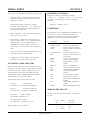
TABLE OF CONTENTS
Page ii RPC-320
SECTION 1 OVERVIEW
DESCRIPTION ................... 1-1
MANUAL ORGANIZATION .......... 1-1
MANUAL CONVENTIONS ........... 1-1
Symbols and Terminology ......... 1-2
TECHNICAL SUPPORT ............. 1-2
SECTION 2 SETUP AND OPERATION
INTRODUCTION ................. 2-1
OPERATING PRECAUTIONS ......... 2-1
EQUIPMENT .................... 2-1
FIRST TIME OPERATION ........... 2-2
Using a PC ................... 2-2
Using a Terminal ............... 2-2
UPLOADING AND DOWNLOADING
PROGRAMS ................. 2-2
Editing program s and program ming hints 2-3
WHERE TO GO FROM HERE ......... 2-4
TROUBLESHOOTING .............. 2-4
SECTION 3 SAVING PROGRAMS
INTRODUCTION ................. 3-1
SAVING A PROGRAM ............. 3-1
AUTORUNNING .................. 3-2
PREVENTING AUTORUN ........... 3-2
LOADING A PROGRAM ............ 3-2
CHANGING EPROM SIZE ........... 3-2
ALTERNATE EPROMS ............. 3-3
COMMANDS .................... 3-3
SECTION 4 SERIAL PORTS
DESCRIPTION ................... 4-1
COM0 SERIAL PORT .............. 4-1
COM1 SERIAL PORT .............. 4-1
RS-422/485 OPERATING INFORMATION . 4-2
RS-422/485 Termination network ..... 4-2
Two wire RS-485 ............... 4-3
Multidrop Network .............. 4-3
ACCESSING SERIAL BUFFERS ....... 4-3
ACCESSING COM0 AND COM1 ....... 4-4
DISABLING CON TROL-C ........... 4-4
SERIAL PORT PIN OUT ............ 4-4
SECTION 5 RAM MEMORY
INTRODUCTION ................. 5-1
CHANGING M EMORY ............. 5-1
BATTERY BACKUP ............... 5-1
Checking the battery ............. 5-1
RESERVED MEMORY ............. 5-2
STORING VARIABLES IN RAM ....... 5-2
BLOCK DATA TRANSFER ........... 5-3
ASSEMBLY LANGUAGE INTERFACE .. 5-3
COMMANDS .................... 5-3
SECTION 6 DIGITAL AND OPTO PORTS
INTRODUCTION ................. 6-1
DIGITAL I/O PORTS ............... 6-1
Digital Port J3 ................. 6-1
Digital Port P6 ................. 6-2
High Current Port L8 ............ 6-2
Optically Isolated Input ........... 6-2
Digital I/O Commands ............ 6-2
High Curr ent Output ............. 6-3
Interfacing Digital I/ O to an opto-module
rack ..................... 6-4
Interfacing to switches and other devices 6-4
Digital I/O program ming exa mple .... 6-4
Pulse Width Modulation (PWM) ...... 6-5
COMMANDS .................... 6-6
SECTION 7 CALENDAR/CLOCK
DESCRIPTION ................... 7-1
SETTING DATE AND TIME .......... 7-1
COMMANDS .................... 7-1
SECTION 8 DISPLAY PORT
INTRODUCTION ................. 8-1
CONNECTING DISPLAYS ........... 8-1
WRITING TO THE DISPLAY ......... 8-1
PROGRAMMING EXAMPLE ......... 8-1
DISPLAY TYPES ................. 8-2
DISPLAY CONNECTOR PIN OUT ..... 8-2
COMMANDS .................... 8-2
SECTION 9 KEYPAD PORT
INTRODUCTION ................. 9-1
PROGRAMMING EXAMPLE ......... 9-1
KEYPAD P ORT P IN OU T - J5 ......... 9-2
SECTION 10 ANALOG INPUT
DESCRIPTION ................... 10-1
CONNECTING ANALOG INPUTS ...... 10-1
Overvoltage conditions ............ 10-1
Grounding .................... 10-1
INITIALIZATION ................. 10-1
Differential Mode ............... 10-2
Examples using CON FIG AIN ....... 10-2
Acquiring Analog Data .............. 10-2
Noise Notes ................... 10-3
Temperature Measurement ......... 10-3
Data logging on a timer tick ........ 10-4
MEASURING HIGHER VOLTAGES .... 10-4
CONVERTING ANALOG MEASUREMENTS 10-4
Measuring 4-20 mA current loops ..... 10-4
AMPLIFIERS .................... 10-5
CALIBRATION .................. 10-5
COMMANDS .................... 10-5

TABLE OF CONTENTS
Page iii RPC-320
SECTION 11 WATCHDOG TIMER
DESCRIPTION ................... 11-1
EXTERNAL RESET ................ 11-1
DESCRIPTION ................... 11-1
OPTICALLY ISOLATED INTERRUPT ... 11-1
INTERRUPT CHARACTERISTICS ...... 11-1
SECTION 12 EXTERNAL INTERRUPT
DESCRIPTION ................... 12-1
PROGRAMMING ................. 12-1
Program examples .............. 12-1
COMMANDS .................... 12-2
SECTION 13 MULTI-MODE COUNTER
DESCRIPTION ................... 13-1
SECTION 14 POWER REDUCTION
FURTHER POWER REDUCTION ...... 14-1
Program Exam ple ............... 14-2
SECTION 15 TECHNICAL INFORMATION
ELECTRICAL SPECIFICATIONS ...... 15-1
MEMORY AND I/O BANK MAP ....... 15-2
MECHANICAL SPECIFICATIONS ..... 15-2
JUMPER DESCRIPTIONS ........... 15-2

SOFTWARE REVISION HISTORY
Page iv RPC-320
V1.04 Release for RPC320
V1.05 BSAVE returned a hardware er ror when ver ify
was bad. In fact, save was OK.
V1.06 LCD graphics hardware CS and reset are
reversed. Compensated in software.
V1.07 MTOP was useless in any system, especially a
32K RAM.
V1.08 Variables E and F would get dropped if
followed by a space.
Added delays between data strob e writes to
LCD display.
V1.09 STR(7, . . .) did not put in a CR into the put
string, causing longer strings to be printed.
V1.10 Initial release for RPC-330.
Added AOT command (330 only)
Added COUNT, ON COM , ON COUNT, ON
LINE, and ON KEYPAD
V1.11 11/29/95
Added day of week to DAT E comm and and
function.
V1.12 12/01/95
Added code to use Atmel 29C040A flash.
V1.13 01/12/96
Added code to support IEE centry series
display (3602-100-05420)
Includes PRINT #port
V1.14 03/28/96
Fixed bug in ON COUNT. Returns error for
lines > 100.
V1.15 06/26/96
PEEK$ could cause BASIC to lock up under
right conditions.
V1.16 02/18/97
ON LIN E OFF could cause program to lock up
if running ON COM.
Syntax error when DISPLAY used with IF-
THEN-ELSE.
Added PE EKF and POKE F commands.

OVERVIEW SECTION 1
Page 1-1 RPC-320
DESCRIPTION
The RP C-320 is an embedded contr oller with a built in
Basic language. Several features make it suitable as a
stand alone unit:
Built in RPBASIC-52 programm ing language
supports hardware using single commands. On card
flash EPROM programm er can save up to 8
programs to 62K , or about 500K tota l.
High speed multimode counter accepts quadrature or
single inputs. Programmable for up/dow n, binary,
divide-by-N, X1, X2 or X4 quadrature counting.
LCD character and gr aphic display a nd keypad p orts
for operator interface.
Two R S-232 ser ial ports, one of which is
configurable for RS-422/485.
Watchdog timer resets card if a program "crashes".
34 digital I/O lines, 9 of which are high current
outputs. 24 of these lines can connect to an opto
rack or other TTL devices.
Eight channel, 12 bit resolution analog to digital
converter. Configurable operational amplifiers
allow you to signal condition inputs or measure
temperature.
32K, 128K, or 512K RAM battery backable to save
process variables and other data when power is off.
32K or 512K flash EPROM to save program s and
data.
The RPC -320 uses an 80C320 CPU operating at 22.1184
Mhz. It can operate stand alone or on a network using
the RS-485 port. Its 4.7" x 7.0" size with 4 mounting
holes makes it easy to mount in a NEMA box.
Compactness is enhanced by on-board analog and digital
terminal strips.
RPBASIC-52 programming language is standard. T his
language is a version of the original Intel BASIC-52. It
was modified for the RPC -320 for control, data
acquisition applications, and on board hardware features.
Program development can take place on your PC, using
your word processor, or on the RPC-320. Programs
from your PC are downloaded using a serial
communication program.
MANUAL ORGANIZATION
This manual provides all the infor mation r equired to
install, configure, and operate the RPC-320. Using this
manual you will be able to:
Interface the RPC-320 to your IBM compatible PC
or terminal.
Understand the operation of the RPC-320 hardware
using RPBASIC-52 programming software.
This manual assumes you are familiar with some type of
BASIC programming software. The syntax used by
RPBASIC-52 is similar to BASIC-52. If you are not
experienced with any BASIC softwar e, y ou may w ant to
refer to books and training programs available through
your local book store. The BASIC-52 Programm ing
Manual has information and examples for the original
commands. Commands unique or modified by
RPBASIC-52 are in the Software Supplement in this
manual.
Each chapter or section is written to first provide an
overview. Then, m ore specific information is provided.
Each chapter has some examples using Basic. A
summary of related hardware commands is at the end of
most chapters.
MANUAL CONVENTIONS
Information appearing on your screen is shown in a
different type.
Example:
RPBASIC-52 V1.0
Copyright Intel (1985) and Remote Processing
Bytes free: 27434

OVERVIEW SECTION 1
Page 1-2 RPC-320
Symbols and Term inology
NOTE: Text under this heading is helpful information.
It is intended to act as a reminder of some
operation or interaction with another device that
may not be obvious.
WARNING:
Information under this heading warns you of
situations which might cause catastrophic or
irreversible damage.
W[-] Denotes jumper block pins.
< xxx> Paired angle brackets are used to indicate a
specific key on your keyboard. F or exam ple
< esc> means the escape key.
BASIC uses the decimal convention for designating
addresses and data. There are times when hexadecimal
notation is more convenient to use. Notation use d in this
manual and BASIC-52 is the ' H' character after the
number. 8CH stands for 8C hexadecimal.
TECHNICAL SUPPORT
If you have a question about the RPC-320 or RPBASIC-
52 and can' t find it in this manual, call us and ask for
technical support. Technic al support hours ar e 9 AM to
4 PM mountain time.
When you call, please have your RPC-320 and BASIC-
52 PROGRAMMING MANUAL ready. Many times it is
helpful to know what the RPC-320 is used for, so please
be ready to describe its application as well as the
problem.
Phone: 303-690-1588
FAX: 303-690-1875
The RPC -320 uses a Dallas Semiconductor DS80C320
processor. Additional information can be obtained from
Dallas Semiconductor (214-450-0448, F AX 214-450
0470), or your distributor.

OVERVIEW SECTION 1
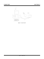
Page 1-3 RPC-320
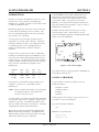
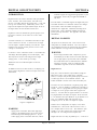
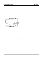
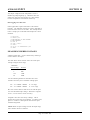
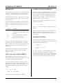
Figure 1-1 System layout

SETUP AND OPERATION SECTION 2
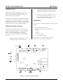
Page 2-1 RPC-320
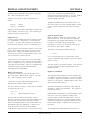
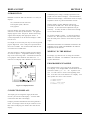
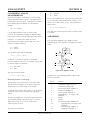
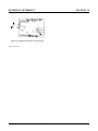
Figure 2-1 Connector location and function
INTRODUCTION
The RPC -320 is ready to program as soon as you
connect it to a ter minal or PC and apply pow er. This
chapter describes what is needed to get a sign- on
message and begin programming.
Requirements for uploading and downloading programs
are discussed. A "W here to go from here" section tells
you what chapters to refer to in order to use the various
capabilities of the RPC-320. Finally, a troubleshooting
section helps out on the most common problems.
OPERATING PRECAUTIONS
The RPC -320 is designed to handle a wide variety of
temperature ranges at low power. These characteristics
require using CM OS com ponents. CM OS is static
sensitive. To avoid damaging these components,
observe the following precautions before handling the
RPC-320.
1. Ground yourself before handling the RPC -320
or plugging in cables. Static electricity
can easily arc through cables and to the card.
Simply touching your PC before you touch the
card can greatly reduce the amount of static.
2. Do not insert or remove components when
power is applied. While the ca rd is a + 5 volt
only system, other voltages generated on the
card which affect other components.
EQUIPMENT
You will need the following equipment to begin using the
RPC-320:
RPC-320 embedded controller
PC with a serial port and com munications
program
or a
Terminal
VTC -9F ser ial cable
+ 5, 200 ma power supply
Refer to Chapter 4, SERIAL PORTS, for wiring
information to make your own serial cable.

SETUP AND OPERATION SECTION 2
Page 2-2 RPC-320
FIRST TIME OPERATION
Become familiar with the locations of connectors before
getting started. See Figure 2-1.
RPC -320 jump ers have been set at the factory to operate
the system immediately. For first time operation, do not
install any connectors or parts unless specified below.
Jumpers should be kept in default positions.
1. Connect power.
The RPC-320 needs + 5 ±0.25 volts at 100 ma.
Any well regulated supply that supplies this will
work. Be careful when using "switching" power
supplies. Some of the se supplies do not regulate
properly unless they are adequately loaded. Don' t
forget that power requirements increase w hen opto
modules are used. G4 opto m odules require up to
20 ma each.
Make sure pow er is off. Connect the power supply
to one of the appropriately marked terminals on the
RPC-320. There two power connectors: P2 and P 6.
Either one may be used to connect power.
2. Hook up to a PC or terminal.
You can use either a PC or CRT term inal to
program the RPC-320. Connect one end of the
VTC-9F connector to the 10 pin COM0 port on the
RPC-320. Refer to Figure 2-1 for connector
location.
Using a PC
Connect the VTC-9F serial cable to the PC's COM1
or COM 2 port. Y ou may need a 9 pin male to 25
pin female adapter. The VTC-9F is designed to
plug directly into the 9 pin serial port connector on a
PC.
Start up your serial communication program. Set
comm unication par ameter s to 9600 baud, 8 da ta
bits, no parity, 1 stop.
Using a Terminal
Follow your terminal instructions to set the baud
rate to 9600 baud, 8 data bits, no parity, and 1 stop.
You may need a 9 pin male to 25 pin male adapter
to connect the VTC-9F.
3. Power up.
Turn on your power supply. On power up a
copyright message is printed.
RPBASIC-52 V1.09
RPC-320
Copyright Remote Processing (1994)
Bytes free: 63740
65,536 bytes of additional expanded memory detected
512K byte EPROM installed
If a nonsense message appears, your terminal or PC
may not be set to the appropriate communication
parameters. If the system still does not respond,
refer to TROUBLESHOOTING later in this chapter.
The sign on message may differ based on the RAM
and flash EPROM installed.
4. Testing.
The system is now in the " imme diate mode" and is
ready for you to start programming. T ype the
following program:
10 FOR X=0 TO 2
20 PRINT "Hello ",
30 NEXT
40 PRINT
Now type RUN. The system will display:
Hello Hello Hello
READY
>
Terminate a program by typing a < Ctrl> -C.
UPLOADING AND DOWNLOADING
PROGRAMS
Downloading program s means transferring them from
your PC (or terminal) to the RPC-320. Uploading
means transferring them from the RPC -320 back to the
PC. This section explains how to do both of these
procedures using generalized instructions for terminal
programs (Procomm , Windows Ter minal, etc.)
When uploading or downloading files, select ASCII text
format. XMODEM, YMODEM, or other formats are
not used.
RPBASIC-52 does not know when you are typing in a
program or if something else (laptop or mainfr ame) is

SETUP AND OPERATION SECTION 2
Page 2-3 RPC-320
sending it char acters. The uploa d and dow nload file
does not contain any special codes; they are sim ply
ASCII characters.
Uploading programs is simply a process of receiving an
ASCII file. You or your program simply need to send
"LIST" to receive the entire program . The default baud
rate (9600) is rather high. The RP C-320' s baud rate is
changed using the CONFIG BAUD command.
Downloading a program requires transmitting an ASCII
file. As you type in (or download) a line, RPBASIC-52
tokenizes, or com piles, that line. The time to do this
depends upon its complexity and how many lines of code
have been entered.
RPBASIC-52 m ust finish compiling a line before starting
the next one. When a line is compiled, a "> " character
is sent. This should be your terminal programs pacing
character for downloading.
If your communications program cannot look for a
pacing prompt, set it to delay transmission after each line
is sent. A 100 ms delay is usually adequate, but your
program may be long and complex and require more
time. A r esult of a short transmission time is missing or
incomplete program lines.
Editing programs and program ming hints
Files uploaded or downloaded are simply ASCII DOS
text files. No special characters or control codes are
used. You may create and edit programs using your
favorite word processor or editor. Just be sure to save
files in DOS text form at.
A technique used to further program documentation and
reduce code space is the use of comments in a
downloaded file. For example, you could have the
following in a file written on your editor:
REM Check position
REM Read output from the pot and
REM calculate the position
2200 a = ain(0) :REM Get position
The first 3 comments downloaded to the RPC -320
are ignored. Similarly, the empty lines between
comm ents are a lso ignored . L ine 2200, with its
comment, is a part of the program and could be listed.
The major pena lty by wr iting a progr am this w ay is
increased download time.
Notice that you can write a program in lower case
characters. RPBASIC-52 translates them to upper case.
Some program mers put "N EW" as the first line in the
file. During debugging, it is common to insert
"temporary" lines. This ensures that these lines are
gone. Downloading time is increased when the old
program is still pre sent. If you like to wr ite programs in
separate modules, you can download them separately.
Modules are assigned blocks of line numbers. Start up
code might be from 1 to 999. Interrupt handling
(keypad, serial ports) might be from lines 1000 to 1499.
Display output might be from 1500 to 2500. The
programmer must determine the number of lines
required for each section.
RPBASIC-52 automatically formats a line for minimum
code space. For example, you could download the
following line of code:
10 fora= 0to5
When you listed this line, it would appear as:
10 FOR A=0 TO 5
Spaces are displayed but not stored. The following line:
10 for a = 0 to 5
would be compressed and displayed as in the second
example above. Spaces are removed. However, spaces
as part of a remark or PRINT are not removed.
Instead of uploading and downloading programs, you can
save them to the on card EPROM. This is useful if you
are using a terminal to write program s. Simply type
SAVE. To retrieve a program, type LOAD.

SETUP AND OPERATION SECTION 2
Page 2-4 RPC-320
WHERE TO GO FROM HERE
If you want to do this: Turn to
Chapter
Save a program 3
Run a program at power up or
reset (autorun) 3
Know m ore abo ut serial por ts 4
Install a different RAM memory chip 5
Using RAM to save variables 5
Run an assembly language program 5
Configure digital I/O lines 6
Detect on/off switch status 6
Use high current outputs 6
Connect an external opto rack 6
Calendar/clock option 7
Connect Displays 8
Use a keypad 9
Measure voltages 10
Using inter rupts 12
Multi-mode counter 13
Use low power operation 14
Refer to the table of contents for a more detailed listing.
TROUBLESHOOTING
You would probably turn to this section because you
could not get the sign on message. If you are getting a
sign on message but can't enter characters, then read
section 5 below . T he following are troubleshooting hints
when you can' t get anything.
1. Check the power source. If it is below 4.65 volts at
the input power terminal, the RPC -320 will reset.
Power is 5 ±0.25 volts. Make sure it is a clean 5
volt source. If it dips intermittently to 4.65 volts
(due to switching noise or ripple), the card will reset
for about 100 ms. If the noise is frequent enough,
the card will be in permanent reset. Check U7, pin
8. If it is high (about 5 volts), then the card is in
reset. This line should be low (about 0 volts).
2. Check the COM 0 port (J3). Remove the connector
from COM 0. Refer to the outline drawing ear lier in
this chapter. Connect an oscilloscope (preferred) or
a voltmeter to pin 3 (Txd) and gr ound. Pin 3 should
be -6 volts or more negative. (Pin 1 is designated
by the v symbol on the connector. Pin 3 is next to
it, nearer the key opening.) If you have -6 volts or
more, press the reset switch. If you have a scope
attached, you should see a burst of activity. With a
volt meter, you should see a change in voltage.
Using a Fluke 8060A set to measure AC, you
should see a momentary reading above 2 volts.
3. Install the serial cable and make sure the voltages
and output activity are still there. Output is from
pin 3 on the VTC-9F. If not, check to make sure
something is not shorting the output.
4. Check the serial parameters on your PC or terminal.
They should be set to:
9600 baud, no parity, 8 data bits, 1 stop
5. If you are receiving a sign on message but not able
to enter characters, check U8, pin 4 for at least -6
volts. When it is near 0 volts, the terminal or PC's
Tx line is not connected. When you press a
character on the terminal or PC, you should see the
voltage go positive. Check the serial cable.
Transmitted signals from the PC or terminal are
from pin 5 on the 10 pin IDC connector.
If all of this fails, call technical support listed in chapter
1.

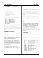
SAVING PROGRAMS SECTION 3
Page 3-1 RPC-320
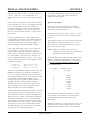
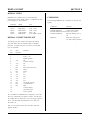
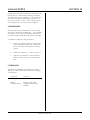
Figure 3-1 W3 autorun jumper
INTRODUCTION
Program s are stored in an EPROM in socket U6. You
can store one or more programs, depending upon
EPROM size. A BASIC program can call another when
a 512K byte EPROM is used.
Maximum program size that can be run at any one time
is about 62K, not including space for variables. 32K
bytes is the maximum program size when a 29C256 IC
type is used to save a program.
A conservative rule to determine program memory
requirements is one line requires 40 bytes. 32K bytes
would stor e 800 lines of code. Your application could
be significantly more or less, depending upon the
number of comm ands/line, comments, and pr int
statements.
Despite the fact you may have a 128K or 512K RAM
installed, the maximum program size RPBASIC-52 can
run at one time is about 60K (including room for some
variable storage). The table below shows the maximum
capacity, maximum number of program lines, program
size at one time, and number of programs for an
EPROM type.
EPROM Max Prog Max No.
type Cap. lines Bytes Progs
29C256 30K 400 32K 1
29C040 509K 12400 62K 8
One program can call another using the EXECUTE n
command. n is from 0 to 7, depending upon the
EPROM type.
NOTE: When a program calls another, the old program
is completely replaced. All variables and
arrays are cleared (set to 0).
To keep variables, you m ust save them before calling the
new progr am. When the new program is running, these
variables are restored. Use PEEK and POKE to read
and save numbers and strings. See Chapter 5, STORING
VARIABLES IN RAM for more inform ation.
Binary data is saved and read from the EPROM using
BSAVE and BLOAD commands. The EP ROM has a
limited number of write cycles (about 1000), so writing
information should be kept to a minimum.
A flash EPROM is non-volatile (retaining data even
when power is disconnected), having an unlimited
number of read cycles and a limited number of write
cycles (about 1,000). A program is not run from
EPROM . It is transferred to RAM and run from there.
Programs in RAM can be m odified. They ar e saved to
EPROM for execution later.
The RPC -320 can autorun on power up or r eset by
removing jumper (W9). W hen autorun is on, the
program in EPROM segment 0 is loaded into RAM and
begins to execute immediately.
This chapter discusses saving programs to EPROM (U6)
and program autoexecution.
SAVING A PROGRAM
For this example, assume you wanted to save the
following program:
20 FOR N= 0 TO 2
30 PRINT "Hello ",
40 NEXT
50 PRINT
If this progr am is not alr eady in, type it in now (or , if
you prefer, use your own program).
Type in the following command:
SAVE
RPBASIC-52 responds with:
Saving 35 bytes
Verifying --- OK

SAVING PROGRAMS SECTION 3
Page 3-2 RPC-320
The time it takes save a program depends upon the
length and complexity of the program and flash EPROM
type. Programming rate is roughly 600 bytes/second. If
the program is not successfully saved to EPROM, an
error message will appear.
Saving a program overw rites the pr evious one. There is
no way to recover the old one since both occupy the
same space.
Using SAVE without any parameters is the same as
typing SAVE 0.
When a 128K (29C 010) or 5 12K (29C 040) EP ROM is
installed in U6, the SAVE segment parameter is 0 or 1
(128K) or 0 - 7 (512K). EXECU TE loads and runs the
program in the segment specified by SAVE. A 32K
(29C256) EPROM can run just one program.
Make the following modifications to the above program
as instructed to see how one program can call another.
There must be a 128K or 512K EPROM installed to run
this code.
Add the following lines:
10 PRINT "Program segment 0"
60 EXECUTE 1
Now type:
SAVE 0
Now m odify lines 10 and 60 as follows:
10 PRINT "Program segment 1"
60 EXECUTE 0
Now type:
SAVE 1
To see the programs operate, type RUN. To stop program
execution, press < Ctrl-C> .
You may notice there is a slight pause between the
printed hello' s and program segment number . This is
the time it takes to clear memory and load the program.
Loading and clearing take appr oximately 0.25 seconds in
a very small program up to 1 second in a very large
program.
AUTORUNNING
To autorun a program:
1. Make sure there is a program in EPROM (from
above). When using a 128K or 512K size EPROM,
make sure the start up progr am was saved to
segment 0.
2. Remove jumper W9.
Push the reset button. The program will run. If there
are any error s, the program will stop (assuming you
have not trapped them with ON ERROR) and display the
error m essage. EX ECUTE n is used within any
program to load and run another program. The EPROM
size must be a 128K or 512K.
PREVENTING AUTORUN
When troubleshooting a program, it' s not always
convenient for an autoexecute file to r un. This is
especially true if the program has been configured to
ignore the < ESC> or < Ctl-C> keys.
To prevent autorun, install jumper W9 before power up
or reset.
LOADING A PROGRAM
There are tim es when y ou may w ish to tempor arily
modify or otherwise test out a change to a program.
Since the program is loaded into RAM in autorun,
modifications are m ade withou t affecting the pr ogram in
EPROM. Use the LOAD or LOAD n comm and to
transfer the EPROM program to RAM.
If you find out that modifications are not desirable or did
not work, you can restore the original program to RAM
using the LOAD command.
CHANGING EPROM SIZE
The RPC-320 can com e with a 32K or 512K flash
EPROM . The size may be changed at any time. Set
W3 according to the type/size.
Type Size W3
Bytes Configuration
29C256 32K [3-5], [4-6]
29C010 128K [3-5], [2-4]

SAVING PROGRAMS SECTION 3
Page 3-3 RPC-320
29C040 512K [1-3], [2-4]
To change the EPRO M in U6, remove the IC and
replace it with the new one. When installing a 29C256,
pin 1 on the IC goes into socket pin 3. The top two
rows of pins are empty.
ALTERNATE EPROMS
Flash EPROMs are more expensive than UV er asable or
OTPs as of this writing. Large volume OEM' s may
wish to use lower cost EPRO Ms.
Program development must use flash EPROM s. When a
program is finished, the flash EP ROM is used as a
master. Use an external program to duplicate progr ams.
Jumper W2 is normally configured for flash EPROM
(W2[3-5] and W2[4-6]). For non-flash EPRO Ms, W2 is
configured for [1-3] and [2-4]. Large volume OEM's
should contact Remote Processing regarding pre-
configuring W2 and W3 for your application.
COMMANDS
The following is a list of RPBASIC-52 commands used
for saving, loading, and executing programs and data.
These commands and functions are explained in the
Software Supplement in this manual.
Command Function
BLOAD Transfers binary data from
EPROM to RAM
BSAVE Transfers binary data from RAM
to flash EPROM
EXECUTE Loads, clears memory, then runs
a program from within a program
LOAD n Loads a program from EPROM
SAVE n Saves a program to flash EPROM

SERIAL PORTS SECTION 4
Page 4-1 RPC-320
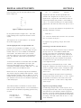
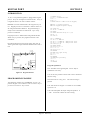
Figure 4-1 Serial port and jumper locations
DESCRIPTION
The RPC -320 has two serial ports that interface to a
printer, terminal, RS-485 network, or other serial
devices. This chapter describes their characteristics and
how to use them. Frequent references are m ade to
commands listed in the BASIC-52 Programm ing Manual
or RPBASIC-52 Software Supplement in this manual.
Please refer to these manuals for more information about
these commands.
Serial por ts are num bered C OM 0 and CO M1. COM 0 is
RS232 only and is used for progr am development.
During r un time, it can be used for other functions.
COM 1 is a general purpose port and is jumperable for
RS-232 or RS-422/485.
Each port has a 256 character interrupt driven input and
output buffer. This allows sending characters without
slowing down program execution. However, if the
PRIN T buffer fills, pr ogram execution is susp ended until
all PRINT characters are in the buffer. Both ports have
a 256 character input buffer. When more than 256
characters are received, excess ones are ignored.
CONFIG BAUD controls baud rate and RS-232/485
mode (COM1 only).
ON C OM$ is useful whe n data is sent in pac kets. This
multitasking command branches to a BASIC subroutine
when a specific character or number of chara cters is
received.
Another useful function is STR. Strings can be
formatted, analyzed for length and content. When used
in conjunction with ON COM$, networ king over RS-485
is much easier than with the original BASIC-52.
COM0 SERIAL PORT
This port uses a VTC-9F serial cable to connect external
serial devices to the port. The cable con sists of a 10 pin
IDC connector wired one-to-one to a DB-9 connector.
Line 10 is sim ply cut off. The pin out is designed so it
plugs directly into the 9 pin serial port connector on a
PC.
CTS is a output and is set to high on power up.
Normally, this tells the other device to send data. The
CTS line is set high or low to hold off communication.
The sending device must have a RTS input. Line 400
sets CTS high and 500 sets it low, or to hold off.
400 LINEB 5,0,(LINEB(5,0) .AND. 247)
500 LINEB 5,0,(LINEB(5,0) .OR. 8)
COM 0 is normally used for program ming. D uring run
time it may be used as a general purpose serial port.
When used for programming or with the INPUT
statement, it will accept ASCII character values from 0
to 127. When used with the GET function, it will return
ASCII values from 0 to 255.
COM1 SERIAL PORT
COM 1 is either an RS-232 or RS-422/ 485 port. A
VTC-9F serial cable, described above, is used for RS-
232 level communications. RS-485 is from screw
terminals. COM 1 has 2 hardw are handshaking lines,
CTS and RTS.
RTS is an input to the card. W hen RT S to the car d is
low, it usually indicates the sender does not want any
data sent to it. The status of this port is read by the
LINEB statement. The example below returns a status
of the RTS line:
100 B = LINEB(5,1) .AND. 32
If B = 32, the sender is not requesting information and
nothing further should be printed.
The CTS line may be set high or low to hold off
communication from a sending device. The sender must
recognize the CTS line. Line 400 sets CTS high and 500
sets it low, or to hold off.

SERIAL PORTS SECTION 4
Page 4-2 RPC-320
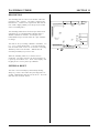
Figure 4-2 Network diagram
400 LINEB 5,0,(LINEB(5,0) .AND. 251)
500 LINEB 5,0,(LINEB(5,0) .OR. 4)
Jumper W4 determines if COM 1 receive is RS-232 or
RS-422/485.
W4[1-2] RS-485
W4[2-3] RS-232 (default)
COM1 default is RS-232. Use the CONFIG BAUD
statement to set the software to RS-422 or RS-485.
When set to RS-422, the transmitter is always on. RS-
485 mode turns on the transmitter only when sending.
RS-422/485 OPERATING INFORMATION
RS-422/485 Termination network
When the RPC-320 is the last physical unit on a network
(RS-485), or it is the only unit (RS-422), the receiver
must be terminated to prevent ringing. Jumper block
W5, 6 installs or removes this network. Insert a jumper
in W5 and W6 to install the network terminator.
Only one slave device on a RS-485 network should have
a terminator installed. The host transmitter should also
have a 100 ohm resistor in series with a 0.1 mfd
capacitor. T he term inator on the RPC -320 includes p ull
up and pull down resistors to prevent lines from floating
and generating er roneous char acters.

SERIAL PORTS SECTION 4
Page 4-3 RPC-320
Figure 4-3 Data packet
Two wire RS-485
The RS-485 port on the RPC-320 is set up for 4 wire
mode. 2- wire mode causes transmitted data to be
received. To use the RPC-320 is this mode, your code
should "flush" the received data or otherwise remove
transmitted information.
Mechanically, to make a 2- wire system, simply connect
T+ to R+ and T- to R-. M ake sure CON FIG BAUD is
set up for RS-485 mode.
Multidrop Network
You can use the RPC-320 in a multidrop network by
using CO M1' s RS-422/485 port. You can c onnect up to
32 units (including other RPC-320' s) over a 4,000 foot
range.
Figure 4-2 shows an example of a multidrop network.
This network includes a host and one or m ore devices.
The host transmits data packets to all of the devices, or
nodes, in the network. A data packet includes an
address, com mand, data, and a checksum. See figure 4-
3. The packet is received by all devices, and ignored by
all except the one addressed.
The relationship described below between nodes and the
host is a master-slave. The host dir ects all
communication. Nodes "do not speak unless spoken to".
Peer to peer communication, while possible with the
RPC-320, is not discussed here.
There are m any communication protocols. F or this
example, a protocol might look som ething like this:
> 22MB1
The protocol starts w ith the < cr> character. This
character synchronizes all units and alerts them that the
next few characters coming down are address and data.
In this case, "> 22" is the units address. "M " is the
comm and and " B1" is the checksum. T he comm and is
terminated with a < cr> character.
The response depends upon the nature of the command.
Suppose the command M means "return a digital I/O
port status". The RPC-320 could read the port and
respond with AA2< cr> . The first A is an
acknowledge, that is no errors were detected in the
message. The data, A2, is a hex number and is broken
down as follows:
Bit/line 7 6 5 4 3 2 1 0
Status 1 0 1 0 0 0 1 0 = A2
Lines 1, 5 and 7 are high while the others are low.
The following program fragment uses ON C OM$ and
STR in a network environment. ON COM$ generates an
interrupt when a < CR> is received. The interrupt
program uses a STR function to deter mine if the da ta
packet was addressed to this card.
10 STRING 200,20
20 ON COM$ 1,0,13,1000
30 $(1) = ">05"
.
.
.
1000 $(0) = COM$(1)
1010 A = STR(8,$(0),$(1))
1020 IF A = 0 THEN RETURN
.
.
Line 20 sets up ON COM$ to interrupt on a < CR> and
branch to line 1000. Line 30 sets up this card' s address.
Line 1010 checks to see if the received message = this
card's address. If not, the subroutine ends. When there
is a match, further processing is performed.
ACCESSING SERIAL BUFFERS

SERIAL PORTS SECTION 4
Page 4-4 RPC-320
You can access C OM0 and COM 1 buffers in three ways:
1. INPUT statement. This removes all characters in
the buffer up to the term inator cha racter and puts
them into a variable.
When using the INPUT statement, program
execution is suspended until a < cr> (Enter key) is
received. W hether this is a problem depends on
your particular application.
INPUT strips bit 7. This means ASCII characters
from 0 to 127 are received.
2. GET function. Char acters ar e removed one at a
time as an ASCII value. A 0 is returned when the
buffer is empty. Use the C OM function to
determine if the buffer is empty or if a 0 is an
ASCII value. Use UIn to select the serial port for
GET.
If you don' t read the b uffer an d the buffer fills, all
subsequent characters are discarded.
3. COM$(n) retrieves all characters in the buffer,
including other control codes (except CR).
ACCESSING COM0 AND COM1
INPUT and GET functions retrieve data using the UIn
comm and. UI0 routes inputs to C OM 0 while U I1 inputs
from the COM1 port. PRINT outputs are set by the
UOn command. UO0 prints out COM0 while UO1
outputs COM1 using the PRIN T comm and. PR INT #1,
is an alternative way to print to COM 1.
The following show how UIn and UOn work.
100 UI0 Set to COM0
110 INPUT A Get data from COM0 port
520 UI1 Switch to COM1 port
530 INPUT B Get data from COM1 port
800 REM Print to COM0
810 PRINT "Temperature:",T
900 REM Print to COM 1
910 PRINT#1, "Set pressure at:",CA
Power up default is set to COM0.
DISABLING CONTROL-C
Program execution is terminated by entering a
< Cntl> < C> . To disable < Cntl> < C> so program
execution is not terminated, execute the following
statement:
DBY(38) = DBY(38) .OR. 1
COMMANDS
The following is a list of RPBASIC-52 commands used
for serial I/O. These commands and functions are
explained in the BASIC-52 Programming Manual and
RPBASIC-52 Software Supplement in this manual.
Command Function
CLEAR COM$ Clears serial input buffer
COM$ Returns string from buffer
COM Returns number of characters
in buffer
CONFIG BAUD Sets serial port parameters
GET Returns a character from the
serial buffer
INPUT Receives string from port
LIST Outputs program listing
PRINT Outputs data in various
formats
PRINT #, Prints to a specified port
SPC Print out n number of spaces
STR String handling commands
TAB Tabs to predetermined
positions
UI0 Reroute inputs to COM0
UI1 Route inputs to COM1
UO0 Rerou te PRIN T statement to
COM0
UO1 Route P RINT statement to
COM1
USING PRINT formatting statement
SERIAL PORT PIN OUT
Pin outs for J1 and J2 are shown below. Unused pins
are open.
J1 & Name Direction
J2 from card
3 Tx Out
4 RTS* In

SERIAL PORTS SECTION 4
Page 4-5 RPC-320
5 RXD In
6 CTS Out
9 Ground
10 +5
*RTS input not in COM0.
A serial cable is made by simply taking a 10 pin female
IDC connector and crim ping a 9 wir e ribbon c able to it.

RAM MEMORY SECTION 5
Page 5-1 RPC-320
Figure 5-1 RAM and W1 jumper location
INTRODUCTION
32K, 128K, or 512K of RAM may be battery backed on
the RPC-320. RAM size can be changed at any time.
RAM is in socket U5.
RAM is backed up when a DS1216DM is installed.
Battery life depends upon RAM size, its power
consumption, ambient temperature, and amount of time
the board is operating. Generally, a battery life of about
3 to 5 years is e xpec ted . Op er ati ng the boar d at 50 °C
reduces battery life by 1/2.
The DS1216DM is also a real time clock. Thus, DATE
and TIM E function s and com mands a re available when it
is installed. See Chapter 7 for more inform ation.
This chapter discusses changing RAM, saving and
retrieving variables, running assembly language
programs, and battery condition. Figure 5-1 shows the
location of U3 and jumper W1.
Increasing RAM size does not necessarily increase the
program size RPBASIC-52 can handle. Maximum
program and variable size is 60K. Additional RAM does
increase the amount of space available for PEEK and
POKE storage.
CHANGING MEMORY
Different types of memory can be installed at any time.
RPC-320 models come with either 32K or 128K of RAM
installed. Maximum is 512K.
To change a memory chip, you need to rem ove the
original chip, install the new one, and set jumper W1.
To install a new memory chip:
1. Turn off power to the RPC-320.
2. Remove the memory chip from U5.
3. Orient the chip so pin 1 is towards the inside.
If installing a 32K RAM, place the chip at the
bottom
of the socket (m emor y chip pin 1 goes into
socket pin 3). The top two socket pins in each row
are empty.
If installing a 128K or 512K, install the chip into the
socket.
4. Check and change, as necessary, jum per W 1 to
conform to the new mem ory.
RAM size Jumper W1
32K [1-2]
128K [1-2]
512K [2-3]
BATTERY BACKUP
An optional battery backup module may be installed.
Principal is the same as installing a RAM chip.
WARNING:
An additional modification must be performed to the
DS1216DM module when a 512K RAM is installed.
Contact Rem ote Processing for details.
To install a module:
1. Remove the RAM IC in U5.
2. Install the DS1216DM in U5.
3. Re-install the RAM chip into the top of the module.
Checking the battery
Battery voltage is approximately 3.0 volts, measured
between pin 16 (ground) and 30 (128K RAM), 14 and 28
(32K RAM), or 16 and 32 (512K RAM) on the IC itself
(not the circuit side of the board). Be sure to power up
the RPC -320 once to a ctivate the batter y backup cir cuit
in the module.
Page is loading ...
Page is loading ...
Page is loading ...
Page is loading ...
Page is loading ...
Page is loading ...
Page is loading ...
Page is loading ...
Page is loading ...
Page is loading ...
Page is loading ...
Page is loading ...
Page is loading ...
Page is loading ...
Page is loading ...
Page is loading ...
Page is loading ...
Page is loading ...
Page is loading ...
Page is loading ...
Page is loading ...
Page is loading ...
Page is loading ...
Page is loading ...
Page is loading ...
Page is loading ...
Page is loading ...
Page is loading ...
Page is loading ...
Page is loading ...
Page is loading ...
-
 1
1
-
 2
2
-
 3
3
-
 4
4
-
 5
5
-
 6
6
-
 7
7
-
 8
8
-
 9
9
-
 10
10
-
 11
11
-
 12
12
-
 13
13
-
 14
14
-
 15
15
-
 16
16
-
 17
17
-
 18
18
-
 19
19
-
 20
20
-
 21
21
-
 22
22
-
 23
23
-
 24
24
-
 25
25
-
 26
26
-
 27
27
-
 28
28
-
 29
29
-
 30
30
-
 31
31
-
 32
32
-
 33
33
-
 34
34
-
 35
35
-
 36
36
-
 37
37
-
 38
38
-
 39
39
-
 40
40
-
 41
41
-
 42
42
-
 43
43
-
 44
44
-
 45
45
-
 46
46
-
 47
47
-
 48
48
-
 49
49
-
 50
50
-
 51
51


Remote Processing Coorporation RPC-320 User manual
- Type
- User manual
Ask a question and I''ll find the answer in the document
Finding information in a document is now easier with AI
Other documents
-
OEHLBACH 6016 Datasheet
-
WTI RPC-4840N User manual
-
Diamond Systems Emerald-MM-Opto User manual
-
Lindy USB to Serial RS485 Converter User manual
-
Black Box IC821A Datasheet
-
Cary Audio Design RS-232 User manual
-
Radio Shack 26-3651 User manual
-
 Matrix Hairstyles GLK24064-25 User manual
-
 Parker Products OPS1200 User manual
-
 Opengear IM4000 User manual


