Page is loading ...

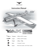
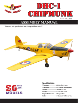
1 Wingspan : 1,630 mm 64.17 in.
1 Length : 1,320 mm 51.97 in.
1 Weight : 3.3 -3.5 kg 7.26-7.70 lbs.
Parts listing required (not included):
1 Servo : 08 servos.
1 Radio : 06 channels.
1
Engine :
55- 61 cu.in - 2 stroke; 91 cu.in - 4 stroke.
1 Electric motor: Rim Fire.60
1 Battery: 5 - 6cells - Li - Poly - 18.5-22.2V - 5,000mAh.
1 ESC : 80A
Made in Vietnam.
SPECIFICATION
INSTRUCTION MANUAL BOOK
ITEM CODE: BH44-A.

2
CHIPMUNK-Item code BH44-A. INSTRUCTION MANUAL.
This instruction manual is designed to help you build a great flying aeroplane. Please read this
manual thoroughly before starting assembly of your CHIPMUNK. Use the parts listing below to
identify all parts.
WARNING.
Please be aware that this aeroplane is not a toy and if assembled or used incorrectly it is
capable of causing injury to people or property. WHEN YOU FLY THIS AEROPLANE YOU
ASSUME ALL RISK & RESPONSIBILITY.
If you are inexperienced with basic R/C flight we strongly recommend you contact your R/C supplier
and join your local R/C Model Flying Club. R/C Model Flying Clubs offer a variety of training
procedures designed to help the new pilot on his way to successful R/C flight. They will also be able
to advise on any insurance and safety regulations that may apply.
TOOLS & SUPPLIES NEEDED.
1 Thick cyanoacrylate glue.
1 30 minute epoxy.
1 5 minute epoxy.
1 Hand or electric drill.
1 Assorted drill bits.
1 Modelling knife.
1 Straight edge ruler.
1 2mm ball driver.
1 Phillips head screwdriver.
1 220 grit sandpaper.
1 90° square or builder’s triangle.
1 Wire cutters.
1 Masking tape & T-pins.
1 Thread-lock.
1 Paper towels.
Some more parts.
HARDWARE PACK
COWLING.
Landing gear.....
To avoid scratching your new airplane, do not
unwrap the pieces until they are needed for
assembly. Cover your workbench with an old
towel or brown paper, both to protect the air-
craft and to protect the table. Keep a couple of
jars or bowls handy to hold the small parts af-
ter you open the bag.
Please trial fit all the parts. Make sure you
have the correct parts and that they fit and are
aligned properly before gluing! This will assure
proper assembly. CHIPMUNK ARF is hand
made from natural materials, every plane is
unique and minor adjustments may have to
be made. However, you should find the fit su-
perior and assembly simple.
The painted and plastic parts used in this kit
are fuel proof. However, they are not tolerant
of many harsh chemicals including the follow-
ing: paint thinner, C/A glue accelerator, C/A glue
debonder and acetone. Do not let these chemi-
cals come in contact with the colors on the
covering and the plastic parts.
PARTS LISTING.
FUSELAGE ASSEMBLY
1 (1) Fuselage.
WING ASSEMBLY
1 (1) Right wing half with pre-installed
aileron.
1 (1) Left wing half with pre-installed
aileron.
1 Some more parts........
Tail section assembly
1 (1) Vertical stabilizer with pre-
installed rudder.
1 (1) Horizontal stabilizer with pre-
installed elevator halves.
SUGGESTION.
NOTE.

3
CHIPMUNK-Item code BH44-A. INSTRUCTION MANUAL.
Caution: this model is not a toy!
If you are a beginner to this type of powered model, please ask an experienced model flyer for help
and support. If you attempt to operate the model without knowing what you are doing you could
easily injure yourself or somebody else. Please keep your safety and well-being in mind at all
times.
Important: before you start construction
Even if you have already built a large number of RC models please read right through these
instructions and check all the kit components against the parts list. We have taken great trouble to
keep construction as simple as possible, without making any compromises in the area of safety.
Note regarding the film covering
Minor creases or bubbles may develop in the film covering due to major fluctuations in weather
conditions (temperature, humidity etc.); in rare cases you may even find a slight warp in a
component. These minor faults are in the nature of film-covered built-up wooden structures, and
can easily be corrected using a heat gun, as commonly used for modelling.
Creases: Blow warm air over the area and rub down with a soft cloth.
Wing warp: Hold the panel twisted gently in the opposite direction to the warp, and apply
warm air to remove the creases from the covering.
Caution! do not heat the film more than is absolutely necessary. If the air or the iron is too hot, the
film may melt and holes may be formed.
This model is highly pre-fabricated and can be built in a very short time. However, the work which
you have to carry out is important and must be done carefully. The model will only be strong and fly
well if you complete your tasks competently - so please work slowly and accurately.
When self-tapping screws have to be screwed into wood, apply a little white glue to prevent
them shaking loose: just squirt white glue into the hole and fit the screw.
+ This is not a toy
+ Be sure that no other flyers are using your radio frequency.
+ Do not smoke near fuel
+ Store fuel in a cool, dry place, away from children and pets.
+ Wear safety glasses.
+The glow plug clip must be securely attached to the glow plug.
+ Do not flip the propeller with your fingers.
+ Keep loose clothing and wires away from the propeller.
+ Do not start the engine if people are near. Do not stand in line with the side of the propeller.
+ Make engine adjustments from behind the propeller only. Do not reach around the spinning
propeller.
SAFETY PRECAUTION.

4
CHIPMUNK-Item code BH44-A. INSTRUCTION MANUAL.
REPLACEMENT LARGE PARTS
8. Spinner.
5. Plastic - enginemount.
2. Wheels
7. Fuel tank.
3. Tail gear set.
1. Oleo struts landing gear
6. Plastic parts of elevator pushrod.
4.nylon steering arm
REPLACEMENT SMALL PARTS
B. Wing panel (B1& B2).
C. Fuselage.
D. Horizontal stabilizer(D1,D2).
F1. Aluminium tube wing.
G. Decal sheets.
F2. Aluminium tube for
Horizontal stabilizer.
G
A. Cowling.
E.Rudder.
4x25mm
5x35mm
3x12mm
5x35mm
35x25mm

5
CHIPMUNK-Item code BH44-A. INSTRUCTION MANUAL.
1 1. Install the rubber grommets and brass
eyelets onto the aileron and flap servo.
INSTALLING THE AILERON- FLAP SERVOS.
Temporary pin to
keep hinge centered.
Assemble then apply drops of thin
C/A to center of hinge,on both sides.
Cut the covering
away from the slot.
1 2. Using a modeling knife, remove the cov-
ering servo tray.
Servo tray.
Aileron
servo tray
Bottom side.
Flap.
Aileron.
Flap.
Aileron.
Bottom side.

6
CHIPMUNK-Item code BH44-A. INSTRUCTION MANUAL.
1 3. Drill 1,5mm pilot holes through the block
of wood for each of the four mounting screws
provided with the servo. Install servo into ai-
leron servo tray as same as picture below.
1 4. Using the thread as a guide and using
masking tape, tape the servo lead to the end
of the thread: carefully pull the thread out.
When you have pulled the servo lead out, re-
move the masking tape and the servo lead
from the thread.
Electric wire.
Thread.
1 5. Instal servo tray with aileron servo into
the wing as same as picture below.
2x10mm.
Aileron.
Install aileron control horn as same as
picture below.
Control horn of Aileron
INSTALLING THE AILERON CONTROL HORN.
Control horn
of Aileron
Repeat the procedure for the other wing
half.
Secure
A+B Epoxy
PLUS glue
Secure

7
CHIPMUNK-Item code BH44-A. INSTRUCTION MANUAL.
1 3. Plug the aileron servo into the receiver
and center the servo. Install the servo arm onto
the servo. The servo arm should be perpen-
dicular to the servo and point toward the mid-
dle of the wing.
1 1. Working with the aileron linkage for
now, thread one clevis onto one of the
threaded wires.
1 2. Attach the clevis to the outer hole in the
control horn. Install a silicone tube on the
clevis.
INSTALLING THE AILERON
LINKAGES.
1 6. Insert the 90 degree bend down through
the hole in the servo arm. Install one nylon
snap keeper over the wire to secure it to the
arm. Install the servo arm retaining screw and
remove the masking tape from the aileron.
1 4. Locate one nylon servo arm, and using
wire cutters,remove all but one of the arms.
Using a 2mm drill bit, enlarge the third hole
out from the center of the arm to accommo-
date the aileron pushrod wire.
1 5. Using pliers, carefully make a 90 degree
bend down at the mark made. Cut off the ex-
cess wire, leaving about 4mm beyond the
bend.
M2 lock nut.
M2 clevis. Snap keeper.
Bend .
Cut.

8
CHIPMUNK-Item code BH44-A. INSTRUCTION MANUAL.
Electric wire.
Thread.
2x10mm.
Flap control horn
2.INSTALLING THE FLAP CONTROL HORN.
Install Flap control horn as same as picture
below as same as the way of aileron.
Repeat the procedure for the other wing
half.
Flap.
A+B Epoxy
PLUS glue
II. FLAP.
1 .Install servo tray with flap servo in to the
wing as same as picture below.
Flap.
Aileron.
Repeat the procedure for the other wing
half.
1.INSTALLING THE FLAP SERVOS.

9
CHIPMUNK-Item code BH44-A. INSTRUCTION MANUAL.
3.INSTALLING THE FLAP LINKAGES.
Flap
control .
Bend.
Flap.
Cut.
Flap.
4x12mm

10
CHIPMUNK-Item code BH44-A. INSTRUCTION MANUAL.
Repeat the procedure for the other wing
half.
Bottom side
Flap Aileron
Secure
INSTALLING LANDING GEAR.
A+B Epoxy
PLUS glue.
3x15mm
5x35mm
5x35mm
See pictures below:

11
CHIPMUNK-Item code BH44-A. INSTRUCTION MANUAL.
Mark point and
drill a hole
2mm.
Secure.
3x15mm
5x35mm
Secure.
Bottom side.
Secure.
Repeat the procedure for the other gear
half.

12
CHIPMUNK-Item code BH44-A. INSTRUCTION MANUAL.
Locate the long piece of wire used for the
throttle pushrod. One end of the wire has been
pre-bend in to a “Z” bend at the factory. This
“Z” bend should be inserted into the throttle
arm of the engine when the engine is fitted onto
the engine mount. Fit the engine to the engine
mount using the screws provided.
See pictures below:
ENGINE MOUNT.
3.5x25mm.
4x25mm.
Drill a hole 4mm
diameter.
120mm
INSTALLING THE ENGINE.
Drill a hole
2.5mm diameter.
Mark point.

13
CHIPMUNK-Item code BH44-A. INSTRUCTION MANUAL.
Secure
35 x25mm
INSTALLING THE STOPPER ASSEMBLY
1 1. The stopper has been pre-assembled
at the factory.
1 2. Using a modeling knife, cut one length
of silicon fuel line (the length of silicon fuel line
is calculated by how the weighted clunk should
rest about 8mm away from the rear of the tank
and move freely inside the tank). Connect one
end of the line to the weighted clunk and the
other end to the nylon pick up tube in the stop-
per.
FUEL TANK.
Left side.
Pushrod wire.
Right side.
1 3. Carefully bend the second nylon tube
up at a 45 degree angle (using a cigarette
lighter). This tube will be the vent tube to the
muffler.
1 4. Carefully bend the third nylon tube down
at a 45 degree angle (using a cigarette lighter).
This tube will be vent tube to the fueling valve.
When the stopper assembly is installed in
the tank, the top of the vent tube should rest
just below the top surface of the tank. It should
not touch the top of the tank.

14
CHIPMUNK-Item code BH44-A. INSTRUCTION MANUAL.
1 9. To secure the fuel tank in place, ap-
ply a bead of silicon sealer to the forward area
of the tank, where it exits the fuselage behind
the engine mounting box and to the rear of the
tank at the forward bulkhead.
1 5. Test fit the stopper assembly into the
tank. It may be necessary to remove some of
the flashing around the tank opening using
a modeling knife. If flashing is present, make
sure none of it falls into the tank.
1 6. When satisfied with the alignment of
the stopper assembly tighten the 3mm x 20mm
machine screw until the rubber stopper ex-
pands and seals the tank opening. Do not over
tighten the assembly as this could cause the
tank to split.
1 8. Feed three lines through the fuel tank
compartment and through the pre-drilled hole
in the firewall. Pull the lines out from behind
the engine, while guiding the fuel tank into
place. Push the fuel tank as far forward as
possible, the front of the tank should just about
touch the back of the firewall.
Blow through one of the lines to ensure the
fuel lines have not become kinked inside the
fuel tank compartment. Air should flow through
easily.
1 7. Using a modeling knife, cut 3 lengths of
fuel line 150mm long. Connect 2 lines to the 2
vent tubes and 1 line to the fuel pickup tube in
the stopper.
Do not secure the tank into place perma-
nently until after balancing the airplane. You
may need to remove the tank to mount the
battery in the fuel tank compartment
Fuel tank.
Silicon not
included.
Tie wrap.

15
CHIPMUNK-Item code BH44-A. INSTRUCTION MANUAL.
1 1. Install one adjustable metal connector
through the third hole out from the center of
one servo arm, enlarge the hole in the servo
arm using a 2mm drill bit to accommodate the
servo connector. Remove the excess mate-
rial from the arm.
INSTALLING THE THROTTLE PUSHROD.
After installing the adjustable metal con-
nector apply a small drop of thin C/A to
the bottom nut. This will prevent the con-
nector from loosening during flight.
Throttle servo
Throttle servo
Throttle pushrod
secure.

16
CHIPMUNK-Item code BH44-A. INSTRUCTION MANUAL.
COWLING.
1 1. Slide the fiberglass cowl over the en-
gine and line up the back edge of the cowl with
the marks you made on the fuselage.
1 2. While keeping the back edge of the
cowl flush with the marks, align the front of
the cowl with the crankshaft of the engine. The
front of the cowl should be positioned so the
crankshaft is in nearly the middle of the cowl
opening. Hold the cowl firmly in place using
pieces of masking tape.
1 3. Slide the cowl back over the engine
and secure it in place using four wood screws.
See picture below.
1 4. Install the muffler and muffler extension
onto the engine and make the cutout in the
cowl for muffler clearance. Connect the fuel
and pressure lines to the carburetor, muffler
and fuel filler valve.
Trim and cut.
Right side
Left side.
Right side
Drill a hole
2mm
3 x 12mm
Drill a hole
2mm

17
CHIPMUNK-Item code BH44-A. INSTRUCTION MANUAL.
Secure.
Left side.
Machine
screw.
Right side
Machine
screw.
Front view.
Install the spinner backplate, propeller and
spinner cone. The spinner cone is held in
place using two 3mm x 12mm machine
screws.
INSTALLING THE SPINNER.
3x12mm
Secure

18
CHIPMUNK-Item code BH44-A. INSTRUCTION MANUAL.
1 Horizontal stabilize installation .
See picture below.
HORIZONTAL STABILIZER, VESTICAL
INSTALLATION.
Secure
SERVO INSTALLATION.
ELEVATOR INSTALLATION.
1 2. Mount the servo to the tray using the
mounting screws provided with your radio sys-
tem.
1 1. Install the rubber grommets and brass
collets into the elevator servo. Test fit the servo
into the servo tray.
elevator servo.
elevator servo.
Assemble then apply drops of thin
C/A to center of hinge,on both sides.
Temporary pin to
keep hinge centered.
Cut the covering
away from the slot.

19
CHIPMUNK-Item code BH44-A. INSTRUCTION MANUAL.
Aluminium tube 9mm
193mm
Epoxy glue
Epoxy glue

20
CHIPMUNK-Item code BH44-A. INSTRUCTION MANUAL.
Elevator control horn install as same as the
way of aileron control horn. Please see pic-
tures below.
Control horn of elevator.
A+B Epoxy
PLUS glue
M2
M2 lock nut.
Elevator pushrod install as same as the way
of aileron pushrod.
ELEVATOR PUSHROD INSTALLATION.
Control horn
of elevator.
Elevator
pushrod.
Bottom side.
C/A glue
Top side.
Bottom side.
ELEVATOR CONTROL HORN INSTALLATION.
/