Page is loading ...

KING CANADA
I
I
N
N
S
S
T
T
R
R
U
U
C
C
T
T
I
I
O
O
N
N
M
M
A
A
N
N
U
U
A
A
L
L
COPYRIGHT © 2013 ALL RIGHTS RESER
VED BY KING CANADA TOOLS INC.
MODEL: 8440N
O
O
I
I
L
L
-
-
F
F
R
R
E
E
E
E
A
A
I
I
R
R
C
C
O
O
M
M
P
P
R
R
E
E
S
S
S
S
O
O
R
R
K
K
I
I
T
T
plusplus
performanceperformance
04/2013

W
W
A
A
R
R
R
R
A
A
N
N
T
T
Y
Y
I
I
N
N
F
F
O
O
R
R
M
M
A
A
T
T
I
I
O
O
N
N
2
2
-
-
Y
Y
E
E
A
A
R
R
L
IMITED WARRANTY
FOR THIS OIL-FREE AIR COMPRESSOR
K
K
I
I
N
N
G
G
C
C
A
A
N
N
A
A
D
D
A
A
T
T
O
O
O
O
L
L
S
S
OFFERS A 2-YEAR LIMITED WARANTY
FOR NON-COMMERCIAL USE.
PROOF OF PURCHASE
Please keep your dated proof of purchase for warranty and servicing purposes.
REPLACEMENT PARTS
Replacement parts for this product are available at our authorized King Canada service centers across Canada.
LIMITED TOOL WARRANTY
King Canada makes every effort to ensure that this product meets high quality and durability standards. King Canada warrants to the
original retail consumer a 2-year limited warranty as of the date the product was purchased at retail and that each product is free from
defects in materials. Warranty does not apply to defects due directly or indirectly to misuse, abuse, normal wear and tear, negligence
or accidents, repairs done by an unauthorized service center, alterations and lack of maintenance. King Canada shall in no event be
liable for death, injuries to persons or property or for incidental, special or consequential damages arising from the use of our
products.
To take advantage of this limited warranty, return the product at your expense together with your dated proof of purshase to an
authorized King Canada service center. Contact your retailer or visit our web site at www.kingcanada.com for an updated listing of our
authorized service centers. In cooperation with our authorized serviced center, King Canada will either repair or replace the product if
any part or parts covered under this warranty which examination proves to be defective in workmanship or material during the
warranty period.
NOTE TO USER
This instruction manual is meant to serve as a guide only. Specifications and references are subject to change without prior notice.
PARTS DIAGRAM & PARTS LISTS
Refer to the Parts section of the King Canada web site for the most updated parts diagram and parts list.
KING CANADA INC. DORVAL, QUÉBEC, CANADA H9P 2Y4
www.kingcanada.com

I
I
M
M
P
P
O
O
R
R
T
T
A
A
N
N
T
T
S
S
A
A
F
F
E
E
T
T
Y
Y
I
I
N
N
S
S
T
T
R
R
U
U
C
C
T
T
I
I
O
O
N
N
S
S
RISK OF EXPLOSION OR FIRE
WHAT CAN HAPPEN
I
t is normal for electrical contacts within the motor and
pressure switch to spark.
If electrical sparks from the compressor come in contact with
flammable vapors, they may ignite, causing fire or explosion.
Restricting any of the compressor ventilation openings will
cause serious overheating and could cause fire.
Unattended operation of this compressor could result in
personal injury or property damage.
HOW TO PREVENT IT
Always operate the compressor in a well ventilated area free
of combustible materials, gasoline or solvent vapors. If
s
praying flammable materials, locate the compressor at least
20 feet away from the spray area. An additional length of hose
may be required.
Store flammable materials in a secure location away from the
compressor.
Never place objects against or on top of the compressor.
Operate compr
essor in an open area at least 12 inches away
from any wall or obstruction that would restrict the flow or
fresh air to the ventilation openings.
Operate compressor in a clean, dry and well ventilated area.
Do not operate compressor indoors in a confined area.
Always remain in attendance with the compressor when it is
operating.
RISK OF BURSTING
WHAT CAN HAPPEN
1. Failure to properly drain condensed water from the tank,
causing rust and thinning of the steel tank.
2. Modifications or attempted repairs to the tank.
3. Unauthorized modifications to the unloader valve, safety
valve or any other components which control tank pressure.
4. Excessive vibration can weaken the air tank and cause
rupture or explosion.
Attachments & Accessories; Exceeding the operating pres-
sure of air tools can cause them to explode.
HOW TO PREVENT IT
Drain tank daily or after every use. If the tank developes a leak,
replace tank or get a new air compressor. Never drill into, weld
or make any modifications to the tank or its attachments.
The tank is designed to withstand specific operating
pressures. Never make adjustments or parts substitutions to
alter the factory set operating pressures.
For essential control of air pressure, you must install a
RISK OF BURNS
WHA
T CAN HAPPEN
T
ouching exposed metal such as the compressor head or
outlet tubes, can r
esult in serious bur
ns.
HOW TO PREVENT IT
Never touch any exposed metal parts on compressor during or
immediately after operation. The compressor will remain hot
several minutes after use.
Do not r
each around pr
otective shrouds or attempt
maintenance until the compressor has cooled down
RISK OF PROPER
TY DAMAGE WHEN
TRANSPORTING COMPRESSOR
WHAT CAN HAPPEN
Oil can leak or spill and could r
esult in fir
e or br
eathing hazar
d,
serious injury or death can result. Oil leaks will damage carpet,
paint or other surfaces in vehicules or trailers.
HOW TO PREVENT IT
Always place compressor on a protective mat when trans-
porting to protect against damage to vehicule from leaks.
Remove compr
essor from vehicule immediately apon arrival.

S
S
P
P
E
E
C
C
I
I
F
F
I
I
C
C
A
A
T
T
I
I
O
O
N
N
S
S
&
&
E
E
L
L
E
E
C
C
T
T
R
R
I
I
C
C
A
A
L
L
I
I
N
N
F
F
O
O
R
R
M
M
A
A
T
T
I
I
O
O
N
N
W
W
A
A
R
R
N
N
I
I
N
N
G
G
ALL ELECTRICAL CONNECTIONS MUST BE DONE BY A QUALIFIED ELECTRICIAN. FAILURE TO COMPLY MAY RESULT IN SERIOUS
INJURY! ALL ADJUSTMENTS OR REPAIRS MUST BE DONE WITH THE COMPRESSOR DISCONNECTED FROM THE POWER
SOURCE. FAILURE TO COMPLY MAY RESULT IN SERIOUS INJURY!
P
P
O
O
W
W
E
E
R
R
S
S
U
U
P
P
P
P
L
L
Y
Y
W
W
A
A
R
R
N
N
I
I
N
N
G
G
:
:
YOUR COMPRESSOR MUST BE CONNECTED TO A 120V
OUTLET, USING A 15-AMP TIME DELAY FUSE OR CIRCUIT BREAKER.
FAILURE TO CONNECT IN THIS WAY CAN RESULT IN INJURY FROM
SHOCK OR FIRE.
G
G
R
R
O
O
U
U
N
N
D
D
I
I
N
N
G
G
Your compressor must be properly grounded. Not all outlets are properly
grounded. If you are not sure if your outlet is properly grounded, have it
checked by a qualified electrician.
W
W
A
A
R
R
N
N
I
I
N
N
G
G
:
:
IF NOT PROPERLY GROUNDED, THIS COMPRESSOR CAN
CAUSE ELECTRICAL SHOCK, PARTICULARLY WHEN USED IN DAMP
LOCATIONS. TO AVOID SHOCK OR FIRE, IF THE POWER CORD IS
WORN OR DAMAGED IN ANY WAY, HAVE IT REPLACED IMMEDIATELY.
If this compressor should malfunction or breakdown, grounding provides
a path of least resistance for electric current, to reduce the risk of electric
shock. This compressor is equipped with a cord having an equipment-
grounding conductor and grounding plug. The plug must be plugged into
an appropriate outlet that is properly installed and grounded in
accor
dance with all local codes and ordinances.
W
W
A
A
R
R
N
N
I
I
N
N
G
G
:
:
TO MAINTAIN PROPER GROUNDING, DO NOT REMOVE OR
ALTER THE GROUNDING PRONG IN ANY MANNER.
1
1
2
2
0
0
V
V
O
O
P
P
E
E
R
R
A
A
T
T
I
I
O
O
N
N
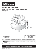
As received from the factory, your compressor is ready to run for 120V
operation. This machine is intended for use on a circuit that has an outlet
and a plug which looks like the one illustrated in Fig.1.
W
W
A
A
R
R
N
N
I
I
N
N
G
G
:
:
DO NOT USE A TWO-PRONG ADAPTOR FOR THEY ARE NOT
IN ACCORDANCE WITH LOCAL CODES AND ORDINANCES. NEVER
USE IN CANADA.
F
F
I
I
G
G
U
U
R
R
E
E
1
1
LENGTH OF
CONDUCTOR
0-25 FEET
26-50 FEET
51-100 FEET
WIRE SIZES REQUIRED
(AMERICAN WIRE GAUGE)
120V LINES
NO.16
NO.16
NO. 14
F
F
I
I
G
G
U
U
R
R
E
E
2
2
E
E
X
X
T
T
E
E
N
N
S
S
I
I
O
O
N
N
C
C
O
O
R
R
D
D
S
S
The use of any extension cord will cause some loss of power. IT
IS RECOMMENDED TO USE A LONGER AIR HOSE INSTEAD
OF AN EXTENSION CORD. Use the chart below in Fig.2 to
determine the recommended minimum wire size (A.W.G-
American Wire Gauge) extension cord. Use only 3-wire
extension cords which have 3-prong grounding type plugs and
3-hole receptacles which accept the tool’s plug.
For circuits that are further away from the electrical circuit box, the
wire size must be increased proportionately in order to deliver
ample voltage to the motor. Refer to Fig.2 for wire length and
size.
PROPERLY GROUNDED OUTLET
CURRENT CARRYING PRONGS
GROUNDING PRONG
S
S
P
P
E
E
C
C
I
I
F
F
I
I
C
C
A
A
T
T
I
I
O
O
N
N
S
S
M
odel ............................................................................................................................................................................................8440N
Voltage ............................................................................................................................................................................................120V
Amperage ........................................................................................................................................................................................3.7A
R
PM (no load speed)......................................................................................................................................................................2,900
Phase ....................................................................................................................................................................................................1
Hertz................................................................................................................................................................................................60Hz
Maximum operating pressure ....................................................................................................................................................100 PSI
CFM @ 40 PSI ..................................................................................................................................................................................0.82
CFM @ 90 PSI ..................................................................................................................................................................................0.60
Tank size ....................................................................................................................................................................2x 1.5 US Gallons

O
O
P
P
E
E
R
R
A
A
T
T
I
I
O
O
N
N
C
C
O
O
N
N
T
T
R
R
O
O
L
L
S
S
C
C
H
H
E
E
C
C
K
K
V
V
A
A
L
L
V
V
E
E
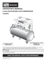
W
hen the air compressor is operating, the check valve is “open”, allowing compressed
air to enter the air tank. When the air compressor reaches “Cut-Out” pressure, the
check valve “closes”, allowing air pressure to remain inside the air tank.
O
O
N
N
/
/
O
O
F
F
F
F
S
S
W
W
I
I
T
T
C
C
H
H
(
(
A
A
)
)
F
F
I
I
G
G
.
.
3
3
Turn this switch ON (press upwards as shown) to provide power to the automatic
pressure switch and OFF to remove power at the end of each use.
P
P
R
R
E
E
S
S
S
S
U
U
R
R
E
E
S
S
W
W
I
I
T
T
C
C
H
H
The pressure switch automatically starts the motor when the tank pressure drops below
the factory set “Cut-In” pressure. It also stops the motor when the air tank pressure
reaches the factory set “Cut-Out” pressure.
R
R
E
E
G
G
U
U
L
L
A
A
T
T
O
O
R
R
(
(
A
A
)
)
F
F
I
I
G
G
.
.
4
4
The air pressure coming from the air tank is controlled by the regulator. Turn the
regulator knob clockwise to increase pressure and counterclockwise to decrease
pressure. To avoid minor readjustment after making a change in the pressure setting,
always approach the desired pressure from a lower pressure. When reducing from a
higher to a lower setting, first reduce the pressure less than that desired, then bring it
up to the desired pressure. Depending on the air requirements of each particular
accessory, the outlet regulated air pressure may have to be adjusted while operating
the accessory.
O
O
U
U
T
T
L
L
E
E
T
T
P
P
R
R
E
E
S
S
S
S
U
U
R
R
E
E
G
G
A
A
U
U
G
G
E
E
(
(
B
B
)
)
F
F
I
I
G
G
.
.
4
4
The outlet pressure gauge indicates the air pressure available at the outlet side of the
regulator. The pressure is controlled by the regulator and is always less than or equal
to the tank pressure.
T
T
A
A
N
N
K
K
P
P
R
R
E
E
S
S
S
S
U
U
R
R
E
E
G
G
A
A
U
U
G
G
E
E
(
(
C
C
)
)
F
F
I
I
G
G
.
.
4
4
The tank pressure gauge indicates the reserve air pressure in the tank.
“
“
O
O
N
N
E
E
T
T
O
O
U
U
C
C
H
H
”
”
1
1
/
/
4
4
”
”
Q
Q
U
U
I
I
C
C
K
K
R
R
E
E
L
L
E
E
A
A
S
S
E
E
C
C
O
O
U
U
P
P
L
L
E
E
R
R
(
(
D
D
)
)
F
F
I
I
G
G
.
.
4
4
Connect the coil hose with a 1/4” male fitting installed and connect it this female quick
release coupler.
D
D
R
R
A
A
I
I
N
N
V
V
A
A
L
L
V
V
E
E
(
(
A
A
)
)
F
F
I
I
G
G
.
.
5
5
The drain valve is located at the base of the air tank and is used to drain condensation
at the end of each use.
S
S
A
A
F
F
E
E
T
T
Y
Y
P
P
R
R
E
E
S
S
S
S
U
U
R
R
E
E
R
R
E
E
L
L
E
E
A
A
S
S
E
E
V
V
A
A
L
L
V
V
E
E
(
(
A
A
)
)
F
F
I
I
G
G
.
.
6
6
If the pr
essur
e switch does not shut of
f the air compr
essor at its cutout pressur
e
setting and the air pressure keeps rising, the safety valve will protect against high
pressure by “popping out” above factory set pressure (slightly higher than the pressure
switch cut-out setting).
W
W
A
A
R
R
N
N
I
I
N
N
G
G
!
!
: If the safety pressure release valve does not work properly, over
pressurization may occur, causing air tank rupture or an explosion. Pull the ring on the
safety valve daily to make sure that the safety valve operates freely. If the valve is stuck
or does not operate smoothly, it must be replaced with the same type of valve.
F
F
I
I
G
G
U
U
R
R
E
E
3
3
F
F
I
I
G
G
U
U
R
R
E
E
4
4
F
F
I
I
G
G
U
U
R
R
E
E
5
5
F
F
I
I
G
G
U
U
R
R
E
E
6
6

S
S
E
E
T
T
-
-
U
U
P
P
,
,
O
O
P
P
E
E
R
R
A
A
T
T
I
I
O
O
N
N
&
&
S
S
T
T
O
O
R
R
I
I
N
N
G
G
S
S
E
E
T
T
T
T
I
I
N
N
G
G
U
U
P
P
Y
Y
O
O
U
U
R
R
A
A
I
I
R
R
C
C
O
O
M
M
P
P
R
R
E
E
S
S
S
S
O
O
R
R
Operate the air compressor in a dry, clean, cool, well ventilated area. Clean or blow off dust or dirt that collects on the air compressor. A clean
a
ir compressor runs cooler and provides longer service. The ventilation openings on your air compressor are necessary to maintain proper
operating temperature. Do not place rags or other containers on or near these openings.
A
A
D
D
D
D
I
I
T
T
I
I
O
O
N
N
A
A
L
L
R
R
E
E
G
G
U
U
L
L
A
A
T
T
O
O
R
R
S
S
A
A
N
N
D
D
C
C
O
O
N
N
T
T
R
R
O
O
L
L
S
S
Since the air tank pressure is usually greater than that which is needed, a regulator is employed to control the air pressure ahead of any
individual driven device. Seperate air transformers which combine the function of air
regulation, moisture and dirt removal should be used where applicable.
P
P
r
r
e
e
p
p
a
a
r
r
a
a
t
t
i
i
o
o
n
n
f
f
o
o
r
r
u
u
s
s
e
e
:
:
1. Before attaching air hose or accessories, make sure the On/Off switch is set to “OFF”
and the air regulator is closed (completely turned counterclockwise).
2. Attach the 1/4” male fitting (A) Fig.7 to one end of coil hose (B), then connect the
male fitting (A) into the quick connect outlet (C), then attach the 1/4” female quick
connect (D) to the other end of the coil hose. Attach optional air tool or supplied
accessories. To prevent air leaks, it is recommended to install Teflon Tape (not
supplied) on the threads at both ends of the coil hose.
W
W
A
A
R
R
N
N
I
I
N
N
G
G
: Too much air pressure causes a hazardous risk of bursting. Check the manufacturer's maximum pressure rating for air tools and
accessories. The regulator outlet pressure must never exceed the maximum pressure rating of the tool being used.
3. Turn the switch to the On position and allow tank pressure to build. Motor will stop when tank pressure reaches “cut-out” pressure.
4. Open the regulator by turning it clockwise. Adjust the regulator to the correct pressure setting. The compressor is ready for use.
After Use:
1. Set the switch to Off.
2. Turn the regulator counterclockwise to set the outlet pressure to zero.
3. Disconnect the air tool or accessory.
4. Pull ring on safety valve (A) Fig. 6, allowing air to bleed fr
om the tank until tank pr
essure is appr
oximately 20 psi. Release safety valve ring.
5. Drain water from air tank. Turn drain valve (A) Fig. 5, counterclockwise to open.
W
W
A
A
R
R
N
N
I
I
N
N
G
G
!
!
:
:
W
W
A
A
T
T
E
E
R
R
W
W
I
I
L
L
L
L
C
C
O
O
N
N
D
D
E
E
N
N
S
S
E
E
I
I
N
N
T
T
H
H
E
E
A
A
I
I
R
R
T
T
A
A
N
N
K
K
.
.
I
I
F
F
N
N
O
O
T
T
D
D
R
R
A
A
I
I
N
N
E
E
D
D
W
W
A
A
T
T
E
E
R
R
W
W
I
I
L
L
L
L
C
C
O
O
R
R
R
R
O
O
D
D
E
E
A
A
N
N
D
D
W
W
E
E
A
A
K
K
E
E
N
N
T
T
H
H
E
E
A
A
I
I
R
R
T
T
A
A
N
N
K
K
C
C
A
A
U
U
S
S
I
I
N
N
G
G
A
A
R
R
I
I
S
S
K
K
O
O
F
F
A
A
I
I
R
R
T
T
A
A
N
N
K
K
R
R
U
U
P
P
T
T
U
U
R
R
E
E
.
.
NOTE: If drain valve is plugged, pull ring on safety valve (A) Fig. 6, and hold until all air pressure has been released. The drain valve can then
be removed, cleaned, and reinstalled.
6. After the water has been completely drained, tur
n drain valve to close. The air compr
essor can now be stor
ed.
F
F
I
I
G
G
U
U
R
R
E
E
7
7

M
M
A
A
I
I
N
N
T
T
E
E
N
N
A
A
N
N
C
C
E
E
&
&
T
T
R
R
O
O
U
U
B
B
L
L
E
E
S
S
H
H
O
O
O
O
T
T
I
I
N
N
G
G
T
T
R
R
O
O
U
U
B
B
L
L
E
E
No start condition
Low pressure
Safety valve releasing
Tank pressure drops
when compr
essor
shuts off
Excessive moitur
e
coming out of air hose
P
P
O
O
S
S
S
S
I
I
B
B
L
L
E
E
C
C
A
A
U
U
S
S
E
E
Fuse blown or circuit breaker tripped
Loose electrical connections
Overheated motor
Air leak in safety valve
Defective check valve
Defective pressure switch or
impr
oper adjustment
Loose drain valve
Loose connections at regulator or
pressure switch
Excessive water in the tank
Humidity too high
C
C
O
O
R
R
R
R
E
E
C
C
T
T
I
I
V
V
E
E
A
A
C
C
T
T
I
I
O
O
N
N
Check for cause of blown fuse/breaker and replace
Check wiring connections
Turn compressor off, wait until total cool-down before restarting
Check valve manually by pulling upwards on ring. If condition
persists replace valve
Replace check valve
Check for proper adjustment and if problem persists, replace
pr
essur
e switch
Tighten drain valve
Check connections for leaks, seal with Teflon tape
Drain tank thr
ough drain valve
Move compressor to area of less humidity. Risk of electric
shock!
T
T
R
R
O
O
U
U
B
B
L
L
E
E
S
S
H
H
O
O
O
O
T
T
I
I
N
N
G
G
M
M
A
A
I
I
N
N
T
T
E
E
N
N
A
A
N
N
C
C
E
E
Before doing any maintenance or adjustments to your air compressor, the following safety precautions should be taken:
- Disconnect electrical power.
- Release air tank pressure.
D
D
a
a
i
i
l
l
y
y
o
o
r
r
b
b
e
e
f
f
o
o
r
r
e
e
e
e
a
a
c
c
h
h
u
u
s
s
e
e
:
:
1. Drain condensation from tank.
2. Check for any unusual noise or vibration.
3. Be sure all nuts and bolts are tight.
K
K
E
E
E
E
P
P
T
T
O
O
O
O
L
L
C
C
L
L
E
E
A
A
N
N
Periodically blow out all air passages with dry compressed air. Clean all plastic parts with a soft damp cloth. NEVER use solvents to clean
plastic parts. They could possibly dissolve or otherwise damage the material.
C
C
A
A
U
U
T
T
I
I
O
O
N
N
: Wear safety glasses while using compressed air.
F
F
A
A
I
I
L
L
U
U
R
R
E
E
T
T
O
O
S
S
T
T
A
A
R
R
T
T
Should your compressor fail to start, check to make sure the prongs on the cord plug are making good contact in the outlet. Also, check
compressor fuse or tripped circuit breakers in the line.

INSTRUCTION MANUAL
COPYRIGHT © 2009 ALL RIGHTS RESERVED BY KING CANADA TOOLS INC.
MODEL: 8200B
18 GA. X 2” BRAD NAILER KIT
plusplus
performanceperformance

WARRANTY INFORMATION
2-YEAR
LIMITED WARRANTY
FOR THIS 18 GA. BRAD NAILER KIT
KING CANADA TOOLS
OFFERS A 2-YEAR LIMITED WARRANTY
FOR NON-COMMERCIAL USE.
PROOF OF PURCHASE
Please keep your dated proof of purchase for warranty and servicing purposes.
REPLACEMENT PARTS
Replacement parts for this tool are available at our authorized KING CANADA service centers across Canada. For servicing, contact
or return to the retailer where you purchased your product along with your proof of purchase.
LIMITED TOOL WARRANTY
KING CANADA makes every effort to ensure that this product meets high quality and durability standards. KING CANADA warrants to
the original retail consumer a 2-year limited warranty as of the date the product was purchased at retail and that each product is free
from defects in materials. Warranty does not apply to defects due directly or indirectly to misuse, abuse, negligence or accidents,
repairs or alterations and lack of maintenance. KING CANADA shall in no event be liable for death, injuries to persons or property or
for incidental, special or consequential damages arising from the use of our products. To take advantage of this warranty, the product
or part must be returned for examination by the retailer. Shipping and handling charges may apply. If a defect is found, KING CANADA
will either repair or replace the product.
KING CANADA
T
OOLS INC. DOR
V
AL, QUEBEC, CANADA
H9P 2Y4

SPECIFICATIONS
Model ............................................................................................................................................................................................8200B
Air inlet ......................................................................................................................................................................................1/4” NPT
Compressed air:
Maximum permissible operating pressure ................................................................................................................120 PSIG (8.3 bar)
Recommended operating pressure range ............................................................................................................................70-100 PSI
Nail range ....................................................................................................................................5/8” to 2” 18ga. brad head finish nails
Width ..........................................................................................................................................................................................1.25mm
Thickness ........................................................................................................................................................................................2mm
Nail capacity ....................................................................................................................................................................100 brad nails
GETTING TO KNOW YOUR NAILER
Nail loading area
Air inlet
Trigger
Magazine
Nail discharge area
AVAILABLE
KING INDUSTRIAL
18 GA. - BRAD NAILS
BN-1816 5/8’’ (16MM APPROX.)
BN-1820
3/4’
’
(18MM
APPROX.)
BN-1825 1’
’ (25MM APPROX.)
BN-1830 1 3/16’’ (29MM APPROX.)
BN-1832 1-1/4’’ (30MM APPROX.)
BN-1838 1-1/2’’ (36MM APPROX.)
BN-1840 1-9/16’’ (38MM APPROX.)
BN-1845
1-3/4’’ (42MM APPROX.)
BN-1850 2’’ (50MM APPROX.)
Air deflector
Magazine latch
Safety release

SAFETY INSTRUCTIONS
• Read and understand this manual and all the safety instructions before operating this nailer. If
you have any questions, please contact our authorized service centres or retailers for help.
• Never allow the use of flammable gases as a power source for the nailer. Use filtered,
lubricated and regulated compressed air only.
• Never use gasoline or other flammable liquids to clean this nailer. Vapors in the nailer will ignite
by a spark and cause the nailer to explode.
• Do not exceed the maximum permissible operating pressure of this nailer (120 PSIG).
• Disconnect the nailer from its air supply before clearing jams, servicing, adjusting and while the
nailer is not in use.
• Do not keep the trigger pulled on contact safety trip mechanism when carrying or holding the
nailer. Never carry the nailer by the air hose or pull on the air hose to move the nailer.
• At the workplace, always wear protective equipment such as Z87 safety glasses, hearing and
head protection.
• Do not use a check valve or any other fitting which allows air to remain in the nailer.
• Do not place your hand or any part of your body in the nail discharge area of the nailer when
connecting or disconnecting from the air supply.
• Never point any operational nail driving tool at yourself or at any other person.

LUBRICATION
AIR SUPPLY AND CONNECTIONS
LUBRICATION AND MAINTENANCE
• Your nailer needs to be lubicated before and after the first time you use it.
• Disconnect the air supply from the nailer before lubricating.
• Turn the nailer so that the inlet is facing up and put
ONE DROP of high speed spindle oil or oil without
detergent into the air inlet. Never use detergent oil or additives. Operate the nailer briefly after adding
oil.
• Wipe off excessive oil at the exhaust. Excessive oil will damage O-rings of the nailer. If a in-line oiler
is used, manual lubrication through the air inlet is not required on a daily basis.
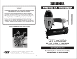
AIR SUPPLY AND CONNECTIONS
WARNING!
THE FOLLOWING ILLUSTRATION SHOWS THE CORRECT MODE OF CONNECTION TO THE AIR
SUPPLY SYSTEM WHICH WILL INCREASE THE EFFICIENCY AND USEFUL LIFE OF THE NAILER.
• Many air tool users find it convenient to use an oiler to help provide oil circulation through the tool and
it increases the efficiency and useful life of the tool. Check oil level in the oiler daily.
• Many air tool users find it convenient to use a filter to remove moisture and impurities which can rust
or wear internal parts of the tool. A filter also increases the efficiency and useful life of the tool. The
filter must be checked on a daily basis and, if necessary
, drained.
• For better performance, install a 3/8” quick connector (1/4” NPT
threads) with an inside diameter of
.315” on your tool and a 3/8” quick coupler on the air hose.
Quick couplers
Quick connector
Oiler
Air hose
Quick
connector
Regulator
Filter
Compressor

FIRING MODES &
VERIFICATION
OPERATING A CONTACT SAFETY TRIP TOOL (SEQUENTIAL MODE):
• The operator is required to have the finger off the trigger and the nose of the nailer to be placed on the
workpiece.
• The contact safety trip mechanism is then depressed against the workpiece and the trigger is pulled to
drive the nail.
• The trigger is released after each nail is driven.
• Move the nailer to the next location and repeat the above procedure.
VERIFICATION
• Disconnect the air supply from the air inlet.
• Empty all nails from the magazine.
• Make sure the trigger and the contact safety trip mechanism moves up and down without sticking.
• Connect the air supply to the nailer air inlet.
• Depress the contact safety trip mechanism against the workpiece without pulling the trigger. The
nailer must not cycle.
Never use the tool if a cycle occurs.
• Hold the nailer clear of the workpiece. The contact safety trip mechanism should return to its original
down position. Pull the trigger. The tool must not cycle.
Never use the nailer if a cycle occurs.
• Depress the contact safety trip mechanism against the workpiece and pull the trigger, the nailer must
cycle.
Operational modes
This nailer may be operated in either “sequential” or “bump fire” mode.
Sequential Mode
This firing method is recommended when precise nail placement is required. In sequential mode, the nailer is actuated by depressing the
nailer nose against the work surface, the trigger then needs to be pulled and released each time a nail is driven.
Bump Fire Mode
This firing method is recommended when less precise nail placement is required. In bump fire mode, the trigger must be depressed with the
nailer nose off the work surface. Then, the nose of the nailer is tapped against the work surface causing a nail to be driven. Each time the
nailer nose is depressed, a nail is driven.

LOADING NAILER & CLEARING JAMS
LOADING NAILER MAGAZINE
• Disconnect the air hose from the nailer air inlet.
• Depress the magazine latch, pull back on the magazine cover.
• Insert a stick of nails into the magazine. Make sure the pointed ends of the nails are as close to the
bottom edge of the magazine as possible, ensuring the head of the nail is aligned with the
appropriate machined groove in the magazine.
• Push the magazine cover forward until the latch catches.
CLEARING JAMS
Disconnect the nailer from the air compressor before adjusting, clearing jams, servicing,
relocating and during non-operation.
• Disconnect the air hose from the nailer air inlet.
• Depress the magazine latch, pull back on the magazine cover and remove all nails.
• Undo the three cap screws (A) and remove the front plate (B) and the intermediary plate (C) from the
nailer. Using pliers, remove the jammed nail from nail discharge area (D) and reinstall all parts in reverse
order and secure them in place using the same 3 cap screws.

OPERATING YOUR NAILER
OPERATING YOUR NAILER
WARNING! protect your eyes and ears. Wear Z87 safety glasses with side shields. Wear hearing
p
rotection. Employers are responsible for ensuring the user or anyone near the nailer wears the
above mentioned safety protection.
WARNING! Check and replace any damaged or worn components.
• Add one/two drops of 30W oil for air tools into the air inlet.
• Install a quick connect fitting to the nailer.
• Connect the nailer to an air compressor using a 3/8” I.D. hose. Make sure the magazine does not
contain any nails and that the air hose has a rated working pressure exceeding 200 psi and a female
quick coupler.
• Regulate the air pressure to obtain 85 psi. Check the operation of the contact safety trip mechanism
following the instructions in this manual.
• Load magazine with nails following the instructions in this manual.
• Reconnect the air hose to the nailer air inlet.
• Test for proper nail penetration by driving nails into scrap wood. If the nails do not achieve the desired
penetration, regulate the air pressure to a higher setting until the desired penetration is achieved. Do
not exceed 100 psi.

MAINTENANCE & TROUBLESHOOTING
CLEANING YOUR NAILER
• Never use gasoline or other flammable liquids to clean the nailer. Vapors in the nailer will ignite
by a spark and cause the tool to explode and result in death or serious personal injury.
• Disconnect the air supply from the nailer.
• Remove tar buildup with #2 kerosene fuel oil or diesel fuel. Do not allow solvent to get into the
cylinder or dammage may occur. Dry off the tool completely before use.
• Air leaking at trigger valve
area.
• Air leaking between
housing and nose.
• Air leaking bewteen
housing and cap assembly.
• Nailer skips a nail.
• Nailer runs too slowly or
has loos of power.
• Jammed nails.
• O-rings in trigger valve are damaged.
• Loose screws in housing.
• Damaged O-rings.
• Bumper damage.
• Loose screws.
• Damaged seal.
• Worn bumper.
• Dirt in nailer nose.
• Dirt or damage prevents nails from mov-
ing freely in the magazine.
• Inadequate air flow to nailer.
• Worn O-ring on piston or lack of
lubrication.
• Damaged O-rings on trigger valve.
• Air leaks.
• Cap seal is leaking.
• Nailer is not sufficiently lubricated.
• Broken spring in cap assembly.
• Exhaust port in cap is blocked.
• Driver guide worn or damaged.
• Nails are bent.
• Magazine or nose screws are loose.
• Damaged driver.
• O-rings must be replaced and safety trip
mechanism must be verified.
• Screws need to be tightened.
• O-rings must be replaced.
• Bumper needs to be replaced.
• Screws need to be tightened.
• Seal must be replaced.
• Bumper needs to be replaced.
• Clean.
• Magazine must be cleaned.
• Fitting hose and air compressor need to
be checked.
• O-rings must be replaced, lubricate.
• O-rings must be replaced.
• Screws and fittings need to be tightened.
• Seal needs to be replaced.
• Lubricate.
• Spring needs to be replaced.
• Damaged internal parts must be replaced.
• Replace driver guide.
• Replace with undamaged nails.
• Screws need to be tightened.
• Replace driver.
Problem Cause Solution
TROUBLESHOOTING CHART
WARNING: Stop using this tool immediately if any of the following problems occur. Serious personal injury could occur. Any
repairs or replacements must be done by a qualified person or an authorized service centre only.
REPLACEMENT DRIVER, BUMPER & O-RING REPAIR KITS
After prolonged use of your Nailer, the internal O-rings, Bumper & Driver may have to be replaced
caused by wear & tear
.
T
o repair
, a complete Driver
, Bumper & O-ring Replacement
Accessory
Kit is available for your Nailer (model: KW
-1
17). Contact your local King Canada distributor for
more information.
KW-117
PARTS DIAGRAM & PARTS LISTS
Refer to the Parts section of the King Canada web site for the most updated parts diagram and
parts list.
/