Geovision IP Camera Quick start guide
- Category
- Security cameras
- Type
- Quick start guide
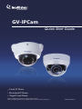
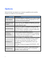
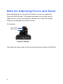
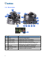
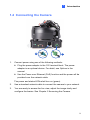
The Geovision IP Camera provides day and night surveillance with features such as automatic IR-cut filter and IR LEDs, adjustable 3-axis pan, tilt, and rotate, and motorized varifocal lens for zooming and focusing from the web interface. It supports H.265 video codec for better compression ratio while maintaining high-quality pictures. With PoE connectivity, you can transmit power and data over a single Ethernet cable, simplifying installation.
The Geovision IP Camera provides day and night surveillance with features such as automatic IR-cut filter and IR LEDs, adjustable 3-axis pan, tilt, and rotate, and motorized varifocal lens for zooming and focusing from the web interface. It supports H.265 video codec for better compression ratio while maintaining high-quality pictures. With PoE connectivity, you can transmit power and data over a single Ethernet cable, simplifying installation.


-
 1
1
-
 2
2
-
 3
3
-
 4
4
-
 5
5
-
 6
6
-
 7
7
-
 8
8
-
 9
9
-
 10
10
-
 11
11
-
 12
12
-
 13
13
-
 14
14
-
 15
15
-
 16
16
-
 17
17
-
 18
18
-
 19
19
-
 20
20
-
 21
21
-
 22
22
-
 23
23
-
 24
24
-
 25
25
-
 26
26
-
 27
27
-
 28
28
-
 29
29
-
 30
30
-
 31
31


Geovision IP Camera Quick start guide
- Category
- Security cameras
- Type
- Quick start guide
The Geovision IP Camera provides day and night surveillance with features such as automatic IR-cut filter and IR LEDs, adjustable 3-axis pan, tilt, and rotate, and motorized varifocal lens for zooming and focusing from the web interface. It supports H.265 video codec for better compression ratio while maintaining high-quality pictures. With PoE connectivity, you can transmit power and data over a single Ethernet cable, simplifying installation.
Ask a question and I''ll find the answer in the document
Finding information in a document is now easier with AI
Related papers
-
Geovision GV-GVS2100 Quick start guide
-
-
-
-
-
-
-
Geovision GV-TDR4702 Quick start guide
-
-
Geovision IP Camera Quick start guide
Other documents
-
Genius IPCAM 300 User manual
-
advidia A-35 Installation guide
-
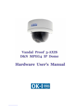 OK-I IP outdoor rugged dome series Hardware User Manual
-
i3 International L16 User manual
-
 USAVision UVS-ADR1300 Quick start guide
-
SecurityMan IPCAM-SD Owner's manual
-
Hikvision DS-2CD4132F-Z Installation guide
-
 avertX HD6012 Quick start guide
-
Milesight 5MP AI 23X PTZ Mini Bullet Plus Camera User guide
-
AVer TR310 User manual


