Page is loading ...

M16
DIGITAL MIXING CONSOLE
USER MANUAL AND USER GUIDE
www.wharfedalepro.com
BUS-1
SEND-1
1
9
2
10
3
11
4
12
5
13
6
14
7
15
8
16
BUS-2
SEND-2
BUS-3
SEND-3
BUS-4
SEND-4
BUS-5&6
SEND-5
BUS-7&8
SEND-6
BUS-9&10
SEND-7
BUS-11&12
SEND-8
10
0
5
5
10
20
30
40
50
60
10
0
5
5
10
20
30
40
50
60
10
0
5
5
10
20
30
40
50
60
10
0
5
5
10
20
30
40
50
60
10
0
5
5
10
20
30
40
50
60
10
0
5
5
10
20
30
40
50
60
10
0
5
5
10
20
30
40
50
60
10
0
5
5
10
20
30
40
50
60
SIG
MIX
DIGITAL MIXING CONSOLE
PEAK
R
L
0
MIXOUTPUT
10
0
5
5
10
20
30
40
50
60
ADJUST
PRESS FOR FINE
1
GAIN
2
GAIN
3
GAIN
4
GAIN
5
GAIN
6
GAIN
7
GAIN
8
GAIN
60dB
0
60dB
0
60dB
0
60dB
0
60dB
0
60dB
0
60dB
0
60dB
0
60dB
0
60dB
0
60dB
0
60dB
0
60dB
0
60dB
0
60dB
0
60dB
0
9
GAIN
10
GAIN
11
GAIN
12
GAIN
13
GAIN
14
GAIN
15
GAIN
16
GAIN
SYSTEM DEFINED
IN 9-16IN 1-8 OUT 1-8
PLAY/PAUSE
SENDS
MASTER
+10
-

TABLE OF CONTENTS
INTRODUCTION ................................................................................................................1
COMMONLY USED CONNECTIONS ................................................................................2
FRONT PANEL ...................................................................................................................3
REAR PANEL ...............................................................................................................4
SPECIFICATION-1 ...............................................................................................................5
SPECIFICATION-3..............................................................................................................6
DIMENSIONS ...................................................................................................................7
MIC – EDIT 1 ......................................................................................................................8
MIC – Edit 2 ........................................................................................................................9
MIC – EQ ..........................................................................................................................10
MIC – EQ LIBRARY...........................................................................................................11
MIC
–
COMPRESSOR......................................................................................................12
SYSTEM............................................................................................................................13
SETUP
–
WIFI...................................................................................................................14
SETUP
–
SCENE..............................................................................................................15
SETUP
–
MULTIMEDIA....................................................................................................16
SETUP
–
FX ASSIGN........................................................................................................17
SETUP – DEFINE LAYER.................................................................................................18
FX
–
MODULATION..........................................................................................................19
FX
–
DELA .......................................................................................................................20
FX
–
GEQ..........................................................................................................................21

Introduction
The M16 mixer is a unique and innovative multi-functional digital mixing console,with many advantages such as small
size,light weight, intuitive and simple operation, user friendly interface and a premium touch screen.
The flagship hardware configuration uses 4th generation industrial floating-point SHARC processing. This delivers
24bits/192kHzAD/DA and powerful interface performance to ensure the highest possible audio quality.
The custom layer, channel link and mute groups make it ideal for live performances, conferences,schools, churches,
cultural auditoriums, weddings, concerts, homes, bands, multi-purpose halls and other sound reinforcement
applications.
Quick Setup Guide
Key Features:
• 16 channel high-performance analogue pre-amplifiers
• 16 microphone inputs with 8 x XLR and 8 x Combi XLR/Jack input connectors
• 16 segment high-precision main output level metering
• 10.1 inch 1280 x 800 pixel HD IPS touchscreen
• 9 x high-quality 100mm motorised faders.
• 8 x assignable balanced outputs
• 6 x built-in effect modules, 2 modulations, 2 delays plus 2 reverbs
• 4 x mono AUX busses, 4 x stereo GROUP buses, 1 x stereo L/R output and 1 x stereo monitor bus output
• 2 x 31-band graphic equalizers
• 2 x USB ports for playback, recording, system updates plus scene import and exports
• 1 x expansion slot for optional USB, Dante and AES/EBU boards
• 1 x RS232 connector - Support Central Control System Access
• Support for iPad remote control
• Support for MP3, WAV, FLAC, APE and other formats of audio source playback
01. Connect the mixer to the electrical outlet with the supplied power AC adapter.
02. Connect the amplifier or active speaker/studio monitor to the main output XLR connector on the back of
the mixer.The default connection for the Amplifier or the Active Speaker/monitor Left channel is on the output
connector number 7. The Amplifier or the Active Speaker/monitor Right channel is on the output connector
number 8.
03. Connect the external audio source (such as the microphone or CD player) to the mixer before the mixer is
powered on. Alternatively, ensure the channel fader is at the bottom level or muted before connecting third-party
equipment.
04. Confirm again that the Master fader and Monitor level is at the bottom and then switch on the console by
holding down the Power button for 5 seconds.
05. Switch on the Amplifier or Active Speaker/monitor (if applicable).
06. Configure the input channel. Rename it and change the representative colour as per the input source.
07. Enable Phantom power if the connected equipment requires Phantom power (ie Condenser microphone)
08. Set the fader to the 0dB position, adjust the gain level and make sure that the meter is working within the
range. The peak light might flash occasionally. The on-screen meter level show the signal level of each channel.
09. If the input signal contains unwanted low-frequency components then the EQ High Pass Filter can be used
to remove some of the low frequencies.
10. Increase or decrease the corresponding frequency band according to the needs of the signal source with EQ.
Control the dynamic range with the compressor.
11. Send the input signal to each effect processor, output Aux's, Group's and Master outputs.
12. Adjust the channel Pan value to move between left and right outputs.
13. Adjust the fader level until the sound is to your preference.
1

8 MIC
1
MIC
2 MIC3 MIC
4
MIC
5 MIC
6 MIC
7 MIC
10
MIC
9 MIC
11
MIC
12 MIC13 MIC
14
MIC
15 MIC
16
MIC
24V/DC INPUT
DIGITAL MIXING CONSOLE
1 OUT2 OUT3 OUT4 OUT
5 OUT
6
OUT
7
OUT
8 OUT
CAUTION
RISK OF ELECTRIC SHOCK
DO NOT OPEN
RS-232/485
HU
AES/EBU
IN
OUT
Centre
Control
Talkback Dynamic
microphone
Gooseneck
microphone
Wireless
microphone
Electric
guitar
In Ear
L R
45°Monitor
Stage Monitor
PC/
Laptop
Processor Keyboard
Saxophone
Electric
piano
Acoustic
guitar
Commonly Used Connections
2

Front Panel
BUS-1
SEND-1
1
9
2
10
3
11
4
12
5
13
6
14
7
15
8
16
BUS-2
SEND-2
BUS-3
SEND-3
BUS-4
SEND-4
BUS-5&6
SEND-5
BUS-7&8
SEND-6
BUS-9&10
SEND-7
BUS-11&12
SEND-8
10
0
5
5
10
20
30
40
50
60
10
0
5
5
10
20
30
40
50
60
10
0
5
5
10
20
30
40
50
60
10
0
5
5
10
20
30
40
50
60
10
0
5
5
10
20
30
40
50
60
10
0
5
5
10
20
30
40
50
60
10
0
5
5
10
20
30
40
50
60
10
0
5
5
10
20
30
40
50
60
SIG
MIX
DIGITAL MIXING CONSOLE
PEAK
R
L
0
MIXOUTPUT
10
0
5
5
10
20
30
40
50
60
ADJUST
PRESS FOR FINE
1
GAIN
2
GAIN
3
GAIN
4
GAIN
5
GAIN
6
GAIN
7
GAIN
8
GAIN
60dB
0
60dB
0
60dB
0
60dB
0
60dB
0
60dB
0
60dB
0
60dB
0
60dB
0
60dB
0
60dB
0
60dB
0
60dB
0
60dB
0
60dB
0
60dB
0
9
GAIN
10
GAIN
11GAIN 12GAIN
13GAIN 14GAIN 15GAIN 16GAIN
SYSTEM DEFINED
IN 9-16IN 1-8 OUT 1-8
PLAY/PAUSE
SENDS
MASTER
+10
-
1. Gain: These are analogue gain controls. The gain setting will
remain unchanged regardless of scene changes.
2. USB: Record/play, scene import/export, system update, WI-FI
dongle for iPad remote control networking.
3. Headphones: Headphone jack and the headphone volume
control.
4. Menu Buttons
4.1. Power On/Off button
a. Press and hold for three seconds to turn the system on or off.
b. Press and hold for one second to lock/unlock the screen and
faders.
4.2. Mute button
Press to activate the mute function. There will be no response
if there are no mute groups set.(Default Mute All)
4.3. System Setup button.
Press to enter the Setup page for System, Channel, Patch, EQ, FX,
GEQ and lots more.
4.4. User Define Layer button.
When User Layer is defined, pressing this button will display the defined layer on the screen. Nothing happens if no
user layer has been defined.
4.5. Layers buttons.
Quick page navigation button to navigate between inputs channel 1 to 8, 9 to 16 and the output channel.
4.6. Buss Send Fader Follow button
Fader follow button allows the user to quickly perform buss send to the channel with the fader.
4.7. USB Music Play/Pause button.
Quick play or pause button. Tap twice to enter the USB Player menu.
4.8. Master Output button.
Displays the Master LR channel strip on the screen.
5. Display screen.
10.1" 1280 × 800 Pixel IPS Touchscreen
6. Rotary encoder
A multi-function purpose encoder controls the selected parameter.
7. 100mm Motorised Faders
8. Master Output Motorised Fader
The main Output Fader adjusts the volume of the master output.
3

4
Rear Panel
1. RS232: Send and receive serial port control signals through the standard RS232 serial port protocol.
2. Power input port: 24V power supply interface. Always use the factory supplied power adapter.
3. Output: All outputs are balanced XLR outputs. Connectors 7 & 8 default to the main output known as
"left and right".
4. Expansion slot: This is an optional expansion slot for optional cards. The available optional cards are
AES/EBU, USB and DANTE. (All cards are stereo)
5. Input: All are balanced input connectors. 12 XLRs - 4 of which are multi-function Combo connectors.
8
MIC
1
MIC
2
MIC
3
MIC
4
MIC
5
MIC
6 MIC
7
MIC
10
MIC
9
MIC
11
MIC
12 MIC13 MIC
14
MIC
15
MIC
16
MIC
24V/DC INPUT
DIGITAL MIXING CONSOLE
1
OUT
2
OUT
3
OUT
4
OUT
5
OUT
6
OUT
7
OUT
8 OUT
CAUTION
RISK OF ELECTRIC SHOCK
DO NOT OPEN
RS-232/485
HU
AES/EBU
IN
OUT
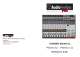
Signal Flow
PHASE
HPF
Dynamics
PEQ
White Noise
4 band
PEQ
4 band
PEQ
4 band
Delay Delay
PEQ
4 band
Delay
Delay
HPF PEQ
4 band
Sine Wave
Pink Noise
Reverb x 2
Delay x 2
GEQ x 2
CHxx PreEQ CHxx PreEQ
CHxx PostEQ CHxx PostEQ
PAN
C H1-16
L &R
MI C 1-16
ME T E R
+4 8 V
P H A NTO M P OW E R
PA TC H
O UT 1- 8
0 d B U
L &R
Mo no B us 1-4
Ste re o B us 5 -8
P FL AFL
Fa d e r
B a l a nce d
G ain
A / D I n
F X Ins e rt
Me te r Fa d e rM e te r
Mo no B us 1- 4
S te re o B us 5 -8
A E S / E B U O UT
P H O N E S O U T
Mute
P re fa d erPo st fa d er
s o lo
P re / Po st fa d er
DAC
U S B P laye r/ Re co rd e r
Mo nito r
Mute
Mute
Fa d e rM e te r
Fa d e rM e te r
Mute
O N
Po st fa d er
Po st fa d er
P re fa d er
P re fa d er
P re fa d er
Mute
O N
S O LO
O N
P re / Po st fa d er
P re / Po st fa d er
P re / Po st fa d er
P re / Po st fa d er
F X 1/2 I ns er t
F X 1/2 I ns er t
F X 1/2 I ns er t
Tr im Leve lDAC
T IP =L E F T
R IN G =R I G H T
O N
O N
Leve l
L &R Me te r
I n s er t I n s er t
E ffe c t Mo dule s
O sc illato r
U S B P laye r/ Re co rd e r
A E S / E B U I N
P re / Po st fa d er
P re / Po st fa d er
s o lo
O N
P re / Po st fa d er
P re / Po st fa d er
s o lo
I n
P re Fa d er
Mute
Me te r
Me te r
Fa d e r
Mo d u lat io n x 2
P re E Q
Po st E Q
S id e C ha in
B A L
O NB A L
O NB A L
PA N
PA N
U S B

5
Specification-1
MIC INPUTS
MIC INPUTS 16 channel inputs (balanced)
Mic input connector
16 XLR and 4 COMBO inputs
Input impedance XLR
3kΩ
Frequency Response 20Hz–20kHz (+/-0.5dB)
S/N Ratio 105dB
Gain Range
70dB
THD 0.005%
Phantom power
+48V (CH-1 to CH-16)
LINE INPUTS
Line Inputs
4 COMBO inputs
Input impedance
20kΩ
Max. Input Level
+30dBu (balanced)
Frequency Response
20Hz–20kHz (+/-0.5dB)
THD 0.008%
S/N Ratio
Gain Range
70dB
105dB
Max. Input Level +20dBu (balanced)
Specification-2
0 to 200msec
Frequency
20Hz-20kHz +/-18dB
HPF, Low, LowMid, High Mid,High
Mode:Bypass /Flat /Library
Threshold= –80dB to 0dB
Attack
0.5msec to 100sec
Release
2msec-2sec
Hold
2msec-2sec
Depth– 80dB to 0dB
EQ
Q= 0.5 to 10.
Gain– 12 dB to +12dB
Ratio1 .0 to 20
INPUT
DYNAMICS
Gate
Compressor
Phase Normal/Reverse
Delay
4 Band Equalizer
Threshold= –80dB to 0dB
Attack
0.5msec to 100sec
Release
2msec-2sec

6
Specification-3
XLR OUTPUTS
Main Outputs ( Balanced )
8 assignable outputs XLR
TH D
0.0 0 5%( 2 0 H z –2 0 k Hz )
Frequency Response
2 0 Hz –20 k Hz ( +/ - 0. 5 d B )
Max . Output level
+18 d B u
Output impedance
470 Ω
Head phones Output connector
TRS jack
Head phones Output Impedance
100 Ω
Max . Out put level
+22 d B u
DigitalI / O
AES / EBU in and out
USB stereo input and REC function
USB Format
2.0
I / O Latency
USB Maximum Memory capacity
32GB
<1.8ms
HEADPHONES
DIGITAL IN/ OUT
Recording format
wav
L/ R + 4 Mono Busses + 4 Stereo Busses
GENERAL
Maximum Voltage Gain 70dB input to bus out
Dynamic range
106dBu analog in to analog out
Cosstalk
-85dB
AD/DA Converter Up to 24Bit/192KHz
Signal processing
40-bit floating point
FX Modules Modulationx2, Delayx2, Reverbx2, 31GEQX2
Screen Resolution
10.1” touchscreen 1280X800
Faders 9 x fully motorised 100mm faders.
System Android
Network
WIFI external USB adapter
Power supply
External. 24V DC (AC 90-240V 50/60Hz)
50W
Dimension (DxWxH) 504x379x136mm
Weight
Net weight: 6.6kg Gross weight: 9kg
HARDWARE
Power consumption
Included Accessories
Wifi USB adapter / User Manual
Power Supply / Power Cord
Specification-4

7
Dimensions
BUS-1
SEND-1
1
9
2
10
3
11
4
12
5
13
6
14
7
15
8
16
BUS-2
SEND-2
BUS-3
SEND-3
BUS-4
SEND-4
BUS-5&6
SEND-5
BUS-7&8
SEND-6
BUS-9&10
SEND-7
BUS-11&12
SEND-8
10
0
5
5
10
20
30
40
50
60
10
0
5
5
10
20
30
40
50
60
10
0
5
5
10
20
30
40
50
60
10
0
5
5
10
20
30
40
50
60
10
0
5
5
10
20
30
40
50
60
10
0
5
5
10
20
30
40
50
60
10
0
5
5
10
20
30
40
50
60
10
0
5
5
10
20
30
40
50
60
SIG
MIX
DIGITAL MIXING CONSOLE
PEAK
R
L
0
MIXOUTPUT
10
0
5
5
10
20
30
40
50
60
ADJUST
PRESS FOR FINE
1
GAIN
2
GAIN
3
GAIN
4
GAIN
5
GAIN
6
GAIN
7
GAIN
8
GAIN
60dB
0
60dB
0
60dB
0
60dB
0
60dB
0
60dB
0
60dB
0
60dB
0
60dB
0
60dB
0
60dB
0
60dB
0
60dB
0
60dB
0
60dB
0
60dB
0
9
GAIN
10
GAIN
11
GAIN
12
GAIN
13
GAIN
14
GAIN
15
GAIN
16
GAIN
SYSTEM DEFINED
IN 9-16IN 1-8 OUT 1-8
PLAY/PAUSE
SENDS
MASTER
+10
-
379
5 0 4
379
8
MIC
1 MIC
2
MIC
3
MIC
4 MIC
5
MIC
6
MIC
7
MIC
10 MIC
9
MIC
11 MIC
12 MIC13 MIC
14 MIC
15
MIC
16
MIC
24V/DC INPUT
M16
DIGITAL MIXING CONSOLE
1
OUT
2
OUT
3
OUT
4
OUT
5
OUT
6
OUT
7 OUT
8 OUT
CAUTION
RISK OF ELECTRIC SHOCK
DO NOT OPEN
RS-232/485
HU
AES/EBU
IN
OUT
5 13
13 6
11°
1. Mic input section: displays the current channels' Link, gain value, phantom power, phase, delay and
effect setting.
2. PEQ: Displays the parameter curve and switch status of the 4-band parametric equalizer.
3. Dynamic: Displays the operating status including the threshold and the compressor.
4. Send: Shows the level and status of the current channel sent to the Buss.
5. Channel level meter: Displays the input signal level of the current channel.
The default display mode is Pre-Fader but can be changed Post-Fader in the Setup Meter Page
if required.
6. Fader value: Displays the current input fader value.
7. Pan: Displays the pan value of the current channel.
8. Channel Name: Displays the name of the current channel. The name and colour of the channel name
can be changed in the channel setup page.
9. Solo: Click to send the selected signal to the monitor Buss, click again to exit the monitor mode.
10. Mute: Click to mute / unmute the selected signal.
-80dB
PAN
20
80
Solo
MIC1
Bus Name
MIC1
48V D FX
Φ
A1
A2
A3
A4
G1
G2
G3
Bus
G4
L&R
EQ
II
Mut e
G
C
MIC - Channel

8
MIC – Edit 1
F X I N S E R T
G E Q 1
Reverb 2Delay 2
Delay 1Modul 2
Reverb 1
Modul 1
L / RGROUP3GROUP2GROUP1 AUX4AUX3AUX2
PREPREPREPRE
POSTPRE
GROUP4
PRE
50 5050 5050 5050 50
0.0 dB0.0 dB0.0 dB0.0 dB0.0 dB0.0 dB0.0 dB0.0 dB0.0 dB
0 0 0 0 0 0 0 0 0
G E Q 2
0 0 0 0 0 0 0 0 0
AUX1
PRE
0.0 dB
M I C 3 - E d it
Edit
E Q
COMP C O P Y L I N K
MIC3&4
POST
P ha s e
Φ
PA N
50 50
Rename
ON
4 8 V
D e lay
8.3 ms
G a in
10dB
L R
1. Edit/EQ/COMM
1.1. Edit - Navigate to the channel configuration page
1.2. EQ – Navigate to the channel EQ configuration page
1.3. COMM – Navigate to the channel Side Chain, Gate, Compressor configuration page.
2. Channel Navigation
Navigate to other channels - without closing and re-opening the setup page.
3. Copy or Link Channel
3.1. Copy - Enable the user to copy the entire channel setting over to another channel.
3.2. Link Channel:
a. Tap once to link horizontal (Left & Right) E.g Ch 1 & 2, 3 & 4
b. Tap twice to link horizontally (Top and Bottom), E.g Ch 1 & 9, 2 & 10
4. 48V/Phase/Delay/Pan/Rename
4.1. 48V - 48V Phantom On/Off. The default is Off. This function is used to supply 48V power to a condenser
microphone or some other device that needs to be powered.
4.2. Phase - Inverts the input signal by 180 degrees when it On. The default is Off.
4.3. Delay -Tap to select and use the physical large Rotary encoder or the on-screen fader on the right to
adjust the Delay value. The delay range is from 0.0 ms to 200 m
4.4. Pan - Tap to select and use the Rotary encoder or the on-screen fader on the right to adjust the Pan value.
4.5. Rename - Tap to enter a new name for the channel.

9
MIC – Edit 2
Φ
5. FX/GEQ Insert
5.1. This area shows the options to insert the effect module.
inserting the effect module into the current channel before
the equalizer, and allowing only one effect module to be inserted
into the input channel. Two effect modules are allowed for the
output channel. When the selected module has been occupied by
another channel, a popup window with the message "This module
is only allowed to be used once and has been used**. Please confirm
whether to force this module?"
5.2. Tap twice on the effect module to enter the effect configuration page.
6. Buss Send
This section displays the status of the parameters sent to the buss by the input channel.
This includes the On/Off button, the send level, the pan level, and the pre-fader or
post-fader setting.
7. Multi-purpose On-Screen Fader
7.1. dB Text Value.
The channel’s input/output signal level. Tap twice to quickly set the input/output level to 0dB.
7.2. On-screen Fader.
The on-screen fader on the right section of the screen is a multi-purpose on-screen fader for a
variety of parameter value adjustments.

10
MIC – EQ
Freq
1. 4 Bands PEQ Graph.
The EQ Graph has 4 draggable selection
points.This allows the user to quickly
adjust the selected band Frequency
and Gain to anestimated position. The
user can then use theon-screen fader or
the large Rotaryencoder to fine-tune
adjust it respective Frequency, Gain,
and Q value.
2. High Pass Filter.
Tap to enable/disable the high pass filter. The default is off.
Use the on-screen fader on the right or the physical Rotary
encoder to adjust the frequency of the high-pass filter (press
and holdthe Rotary encoder for fine tuning). The frequency
range is 16Hz to 400Hz. The default is 16Hz. This filter is very
important for cutting out the low-frequency noises coming in
from a stage. If the signal source has no low-frequency information,
it is wise to use a high pass filter.
3. 4-Band PEQ buttons
Click to select the band and the frequency, gain and Q (width) value.
4. EQ Parameter Setting
Adjust the Frequency, Gain and Q (width) value. Tap to select then use the on-screen fader or
the physical Rotary encoder to adjust the value.
Gain – Range +/-18dB. The default is 0dB
Frequency – Range from 20Hz to 20kHz for the 4 bands of EQ. The default frequencies for High Band is 4kHz,
High-Mid Ban is 1kHz, Low-Mid band is 200Hz and Low band is 60Hz.
Q – Q value range from 0.5 to 10.0. The default value is 0.
5. ByPass
Tap to ByPass the PEQ. Default is Off.
6. Flat
Tap this Flat button to reset the Graph setting back to flat position. Default is Off.
7. EQ Library
Tap the drop-down arrow to view the saved EQ library and enter into the EQ Library Setup page.

11
MIC – EQ Library
Freq
2.2. New.
Tap the New button. A pop-up window will appear for the name of the new EQ library.
This will save the current setting to the newly created EQ library.
2.3. Rename.
Select the library from the list, then tap on the Rename button. A popup window will
appear asking for the New Name
2.4. Import.
Insert a USB stick to the mixer front-panel USB port. Tap the Import button and import the saved
EQ library from the USB stick. NOTE - If the EQ library name already exists, it will be replaced with
the newly imported library.
2.5. Export.
Insert a USB stick to the mixer front-panel USB port. Select the EQ library from the list then tap the
Export button to export the selected EQ library to the USB stick.
3. Load/Save EQ Library.
3.1. Load Existing Library.
Select the library from the list then tap on the Load button.
3.2. Save/Update Library.
Select the library from the list then tap on the Save button to overwrite it with the current EQ setting.
EQ Library Page:
This page contains a list of the functions
and library files for the PEQ library.
1. EQ library file list.
The equalization library contains the
serial number, selection,name, and
time of creation/ update.
2. EQ library function module.
2.1. Delete library file.
When a library file is selected, Tap the
"Delete" button and see a popup dialogue
box "Do you want to delete this library
file? " Click "Yes" to delete or "No" cancel
the operation.

12
MIC - Compressor
20.0 dB
20.0 dB
20.0 dB
20.0 dB
Ratio
1. Gate.
The Y-axis represents the threshold and the X-axis
represents the time factor. The rising line determines
the attack time.The horizontal curve is the hold time,
and the descent line determines the release time.
1.1. On/Off.
Tap this button to enable or disable the Gate.
The default is Off.
1.2. Threshold.
Threshold Range is from -56dB to 0dB. The default is -56dB.
1.3. Attack:
Attack time is from 0ms to 100ms. The default is 0ms.
1.4. Release:
The Release time is from 2ms to 2000ms. The default is 2ms.
1.5. Hold:
The Hold time is from 2ms to 2000ms. The default is 2ms.
1.6. Range:
The Range is from -80dB to 0dB. The default is -80dB
2. Compressor.
2.1. On/Off
Tap this button to enable or disable Compressor.
The default is Off.
2.2. Threshold:
The Threshold Range is from -56dB to 0dB.
The default is -56dB.
2.3. Attack:
The Attack time is from 0ms to 100ms. The
default is 0ms.
2.4. Release:
The Release time is from 2ms to 2000ms.
The default is 2ms.
2.5. Gain:
Gain is from -12dB to +12dB. The default is -12dB.
2.6. Ratio:
The Ratio is from 1.0 to 20.0. The default is 1.0
3. Side Chain
Click the drop-down button to select the side chain
channel from the list.
The user can select Pre or Post EQ channel settings
for the Side Chain.
4. Compressor Library
Uses the same style of operation as found in the
EQ Library.

13
System
1. Scene
Displays the current scene name,
date and time.
2. System Information
Displays the mixer IP address and
the current software version.
3. Oscillator
Test and calibrate the system with
the oscillator.
3.1. Oscillator On/Off
Enables or disables the oscillator.
3.2. White noise:
The level is from -76dB to 0dB. The
default is -30dB.
3.3. Sine wave:
The level is from -76dB to 0dB. The default is -30dB.
The Frequency is from 10Hz to 20kHz.
The default is 1kHz.
3.4. Pink noise.
The level is from -76dB to 0dB. The default is -30dB.
4. System.
For maintenance and home screen options.
This feature is mainly for the service engineer.
5. Language
The default language for the mixer text display is English. In the future, there is a possibility to support
the multi-lingual display.
6. Brightness
This adjusts the display brightness. There are six brightness levels to choose from. The default is level 3.
The system will resume with the last brightness setting upon system restart.
7. Monitor/Headphone
There is a headphone jack and an analogue knob level control to control the headphone volume on the upper
right corner of the mixer. The two balanced output connectors at the back are used for monitor speaker by default.
The user can change the signal from PFL or AFL by tapping the on-screen AFL/PFL button. The default is AFL.
The level range is adjustable from -80dB to 0dB. The default is -20dB. The Mute function enables the user to mute
or unmute the monitor buss. The default is unmuted.Note: The headphone signal is the same as the monitor signal.
In addition to the analog gain control, both the level and the mute are controlled.
The level meter display shows the real-time signal.

14
Setup-WiFi
8. Wi-Fi Section
8.1. Before setting up the connection between the iPad
and the mixer please make sure that the WIFI dongle
has been plugged into the mixer's USB port. The remote
control (Wi-Fi) distance depends on the power (coverage)
of the wireless router.
1- Click the Wi-Fi On/Off button to enable or disable the
Wi-Fi feature. Then select your network from the list.
2-Enter the password for the selected network.
8.2. AP Mode Connection Setup
In an area where there is no Wi-Fi coverage AP mode can be used. Tap the AP/Hotspot On/Off
button to enable or disable AP mode. Once the AP is On the system will display the default SSID
name and a blank password. Change the SSID name and password to setup the AP/Hotspot.
iPAD Setting
1. Download the Wharfedale Pro M16 app from the iPAD OS app store.
https://apps.apple.com/gb/app/m16-mixer/id1474073087
2. Ensure the iPad is connected to the same network as per the mixer setting - or select the AP SSID
name set in the mixer.
3. Launch the app and scan for the mixer. Tap the connect button when mixer is found.
Optionally, the user can enter the IP address to connect to the mixer if there are more than one
device is found.

15
Setup - Scene
When a scene is selected tap the Delete button to delete it.
A popup the dialog box with “Confirm whether
to delete the scene” will show. Tap “Yes” to
confirm the deletion or “No” to cancel the operation.
2.2. New
Tap the New button to create a scene with the current configuration.
2.3. Copy
Copy the selected scene with another new scene name.
2.4. Rename
Rename the selected scene.
2.5. Import
a. Tap the Import button and you will see a popup window displaying a list of available scenes on the
plugged-in USB drive.
b. Choose the file from the list to import. A success or failure dialog box will pop up to show the import status.
c.The system will add a text of "-USB" to the end of the file if an existing scene name is found in the system.
2.6. Export
Ensure the "Export" box is ticked in the selected scene list then tap the Export button to confirm the export of
the selected scenes. A dialog box will pop up to show the export status.
3. Load/Save
3.1. Load
Tap the scene name from the list to selected it - then tap the Load button to load the selected scene.
3.2. Save
Save the current configuration to the selected scene.
Scene Page
1. Scene List
The scene list contains the serial number,
selection, name,creation or update time.
Tap the list to select the scene.
2. Scene function module
2.1. Delete

16
Setup - Multimedia
1. Play List
The system will read the files from the attached USB
drive for any file format of MP3, WAV, FLAC, or APE
and then will display the details in this section.
2. Record and Play Meter
Shows the recording signal or current playback
signal level.
3. Record/Playback Mode
3.1. USB
Source from/to the mixer from the front-panel USB ports
3.2. DiGi
Source from/to the mixer rear panel expansion card slot.
This could be an optional USB Card, AES/EBU Card or
Dante Card.
3.3. Trim
Increases / decreases the input/output level
3.4. Fader
Input/output level
3.5. Output
Assign a USB or AES/EBU signal to the output Buss.
4. Record/Playback Operation button
4.1. Previous
Go to the Previous audio track
4.2. Next
Go to Next audio track
4.3. Play/Pause
Play/Pause the audio
4.4. Shuffle
Shuffle play from the list
4.5. Record
Start recording

17
Setup-FX Assign
FX Assign:
This page allows the user to add the FX or GEQ module
to the Inputs or Output channel quickly without going
through 'channel by channel'.
1. Assignment type
Configuration of the FX, Output patch, Custom layer or
Mute group
2. Assignment section
2.1. Select a channel
2.2. FX Module selection
2.3. Clear button will clear all assignments
Note:
- Each FX/GEQ module can only be used once. If it was assigned to another channel, the same FX/GEQ
module assigned to another channel will be removed from the previous channel.
- Input or Output can have two FX/GEQ modules. Eg. Mod1/Rev1, Mod1/Rev2, Mod2/Rev1, Mod2/Rev2,
Mod1/GEQ1, Del/GEQ2 etc.O
This page allows the user to customise the output to any of the output
connectors or define their own preferences output format.
1. Assignment type
Configure the FX, Output patch, Custom layer or Mute group
2. Assignment section
2.1. Select a channel
2.2. Output Connectors
2.3. Default button will reset the output assignment back to factory setting.
2.4. Custom button will load the user defined custom output setting.
2.5. Clear button will clear the current setting
Setup-Output Patch

18
Setup – Define Layer
The M16 system provides a User Define layer
option to allow the user to customise a page with
8 channels. The User Define layer can be made
up of a combination of inputs and outputs.
1. Assignment type
Configuration the FX, Output patch, Custom layer
or Mute group
2. Assignment section
2.1. Tap the Defined Layer button at the bottom
to enable the editing mode.
2.2. Select an input/output
2.3. Tap the output box to assign the selected
channel to the selected position
Note:
Editing mode enable only if the “Defined Layer” button is enabled. The default is disabled.
The Mute button will mute ALL input and output channels when pressed
in its default setting. The user has the option to customise the mute group.
1. Assignment type
Configuration the FX, Output patch, Custom layer or Mute group
2. Assignment section
2.1. Tap the Mute Group button at the bottom to enable the editing mode.
2.2. Select the input/output to mute or unmute
2.3. Mute All
System will select all inputs/outputs when tapped
2.4. Clear
Clear the current selection.
Setup – Mute Group
/