Schwinn 430i Assembly & Owner's Manual

Category
Fitness, gymnastics & weight training
Type
Assembly & Owner's Manual
This product is compliant with the
applicable CE requirements.
ASSEMBLY MANUAL / OWNER’S MANUAL
430i
2
Important Safety Instructions - Assembly 3
Safety Warning Labels / Serial Number 4
Specications 5
BeforeAssembly 5
Parts 6
Hardware 7
Tools 7
Assembly 8
Moving the Machine 20
Leveling the Machine 20
Important Safety Instructions 21
Features 22
Console Features 23
Operations 28
Mounting and Dismounting 28
Workout Incline Adjustment 28
Power Up / Idle Mode 29
Quick Start Program 30
UserProles 30
Pausing or Stopping 34
Results/CoolDownMode 35
GOALTRACKStatistics 35
Console Service Mode 37
Maintenance 38
Maintenance Parts 39
Troubleshooting 40
TABLE OF CONTENTS
Nautilus,Inc.,www.NautilusInc.com,18225NERiversideParkway,Portland,OR97230,U.S.A.-CustomerService:
[email protected] | Printed in China | © 2013 Nautilus, Inc. | ® indicates trademarks registered in the United States. These
marks may be registered in other nations or otherwise protected by common law. MyFitness Pal® is a registered trademark of its
owner.
Tovalidatewarrantysupport,keeptheoriginalproofofpurchaseandrecordthefollowinginformation:
Serial Number __________________________
Date of Purchase ____________________
To register your product warranty, contact your local distributor.
If you have questions or problems with your product, please contact your local Schwinn distributor.
To find your local distributor, go to: www.nautilusinternational.com
3
IMPORTANT SAFETY INSTRUCTIONS
-ASSEMBLY
This icon means a potentially hazardous situation which, if not avoided, could result in death or serious injury.
Obey the following warnings:
Read and understand all warnings on this machine.
Carefully read and understand the Assembly instructions.
Keep bystanders and children away from the product you are assembling at all times.
Do not connect power supply to the machine until instructed to do so.
Do not assemble this machine outdoors or in a wet or moist location.
Make sure assembly is done in an appropriate work space away from foot traffic and exposure to bystanders.
Some components of the machine can be heavy or awkward. Use a second person when doing the assembly steps
involving these parts. Do not do steps that involve heavy lifting or awkward movements on your own.
Set up this machine on a solid, level, horizontal surface.
Do not try to change the design or functionality of this machine. This could compromise the safety of this machine and will
void the warranty.
If replacement parts are necessary, use only genuine Nautilus replacement parts and hardware. Failure to use genuine
replacement parts can cause a risk to users, keep the machine from operating correctly and void the warranty.
Do not use until the machine has been fully assembled and inspected for correct performance in accordance with the
Manual.
Read and understand the complete Manual supplied with this machine before first use. Keep the Manual for future
reference.
Do all assembly steps in the sequence given. Incorrect assembly can lead to injury or incorrect function.
This product contains magnets. Magnetic fields can interfere with the normal use of certain medical devices at a close
range. Users may come into proximity of the magnets in the assembly, maintenance, and/or use of the product. Given the
obvious importance of these devices, such as a pacemaker, it is important that you consult with your medical provider
in connection with the use of this equipment. Please consult the “Safety Warning Labels and Serial Number” section to
determine the location of the magnets on this product.
4
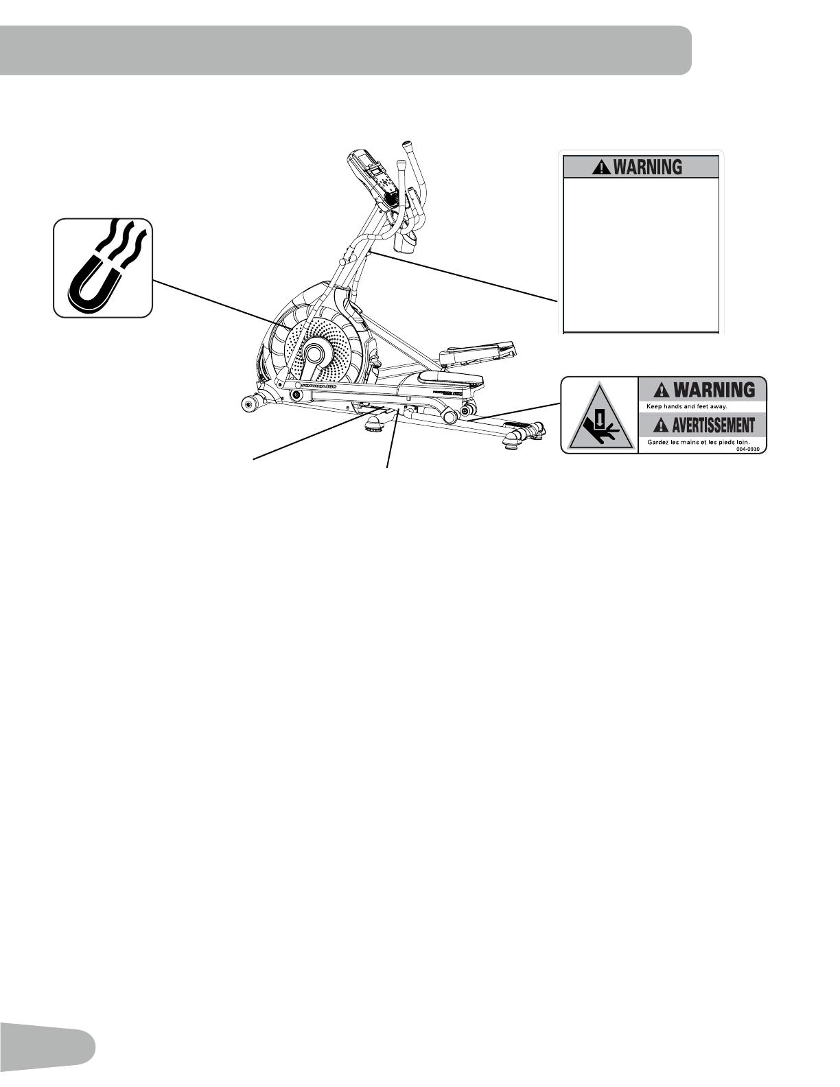
SAFETY WARNING LABELS AND
SERIAL NUMBER
Serial Number
Product Specifications
REVISIONS
ECO
REVISION
REV DESCRIPTION
APPROVED
DATE
TITLE.
PART NO.
REV.
SHEET 1 OF 1
SCALE: 1:1
DO NOT SCALE DRAWING
1. ALL ITEMS MUST BE RoHS COMPLIANT
2. ALL DIMENSIONS APPLY BEFORE PLATING OR COATING.
3. REMOVE ALL BURRS, BREAK SHARP EDGES 0.5 MM MAX.
4. ALL MACHINES SURFACES Ra 3.2 uM.
5. ALL APPLICABLE NAUTILUS STANDARDS AND
SPECIFICATIONS APPLY.
6. ALL DIMENSIONS ARE IN MILLIMETERS
7. ALL DUAL DIMENSIONS ARE IN INCH
UNLESS OTHERWISE SPECIFIED:
METRIC
THIRD ANGLE
PROJECTION
INTERPRET DIMENSIONS AND TOLERANCES
PER ASME Y14.5M - 1994
2.5
1.5
0.75
0.25
X.
X.X
X.XX
X.XXX
ANGULAR
C
SIZE
This document is the property of Nautilus, Inc. It may not be reproduced in whole or part, provided to third parties, or used for any purposes other than the performance of work for Nautilus, Inc. without written authorization. All rights are reserved, including copyrights.
TOLERANCES.
DRAWN
DESIGNED
DATE
METRIC_C_REV G
NAUTILUS, INC.
16400 SE NAUTILUS DRIVE, VANCOUVER, WA 98683
LIFECYCLE
7-22-10
APPROVALS
- -
- - - -
WARRANTY ITEM:
A RELEASED
NPI 13149 DLOVELY
7-22-10
D.LOVELY
D.LOVELY
07 /22 / 2010
D.LOVELY
A
004-0930
CRUSH WARNING
21.78mm
54.8mm
MATERIAL.
COLOR.
DIE LINE
PMS 152
PMS 109
BLACK
WHITE
Labels must be created from an agency approved tamper proof labeling system
such as "UL Recognized component marking and labeling system (example: UL PGGU2) or equivalent.
Label and adhesive must be rated for surface it is applied to (painted metal or ABS plastic),
Label and adhesive must be rated for 60 degrees C minimum. Labels must meet UL 1647 Permanence of Marking Test.
Lisez et assimilez tous les avertissements
apposés sur cet appareil.
Gardez les enfants et les animaux de
compagnie éloignés de cette machine en
tout temps
Déconseil aux enfants âgés de
moins de 14 ans.
Lisez et familiarisez-vous avec le Manuel
du propriétaire et avec tous les
avertissements avant d’utiliser cette
machine.
Soyez prudent lorsque vous utilisez cet
équipement pour ne pas vous infliger de
graves blessures.
Cette machine supporte un poids
maximal de 300lbs. (136kg).
Remplacez toute étiquette
d’avertissement endommae, illisible
ou manquante.
La fréquence cardiaque qui s’affiche
sur la console est une approximation
et doit être utilisée seulement à titre
indicatif.
Read, understand and obey all
warnings on this machine.
Keep children away.
Not intended for use by anyone
under 14 years of age.
Prior to use, read and understand
the Owner’s Manual.
Injury or death is possible if
Caution is not used while using this
machine.
The maximum user weight for this
machine is 300 lbs (136 kg).
Replace any “Caution”, “Warning”
or “Danger” label that is illegible,
damaged, or removed.
The heart rate displayed is an
approximation and should be used
for reference only.
8002739_B
5
SPECIFICATIONS
Before Assembly
Select the area where you are going to set up and operate your machine. For safe operation, the location must be on a
hard, level surface. Allow a workout area of a minimum 193.4 cm x 300 cm ( 76.2” x 118.1” ). Be sure that the workout
space you are utilizing has adequate height clearance, taking into consideration the height of the user and the maximum
incline of the elliptical machine.
Basic Assembly Tips
Follow these basic points when you
assemble your machine:
Read and understand the “Important
Safety Instructions” before assem-
bly.
• Collect all the pieces necessary for
each assembly step.
• Using the recommended wrenches,
turn the bolts and nuts to the right
(clockwise) to tighten, and the left
(counterclockwise) to loosen, unless
instructed otherwise.
• When attaching 2 pieces, lightly
lift and look through the bolt holes
to help insert the bolt through the
holes.
• The assembly can require 2 people.
160.5 cm
( 63.2” )
178.1 cm
( 70.1” )
71.5 cm
( 28.2” )
Maximum User Weight: 136 kg ( 300 lbs. )
Machine Weight: 74.5 kg ( 164.2 lbs. )
Total Surface Area (foot print) of equipment:
12734.2 cm
2
( 1976.8 inches
2
)
Power Requirements:
Operational Voltage: 220V - 240V AC, 50Hz
Operating Current: 0.4A
Regulatory Approvals:
ThisproductconformstotheapplicableENISO20957InternationalStandardsforStationaryTrainingEquipment,ClassH.
DO NOT dispose of this product as refuse. This product is to be recycled. For proper disposal of this product,
please follow the prescribed methods at an approved waste center.
3.0m ( 118.1” )
1.93m
( 76.2” )
0.6m
( 24” )
0.6m
( 24” )
0.6m
( 24” )
0.6m
( 24” )
6
PARTS
1
4
6
5
2
3
12
7
8
10
11
9
16
14
13
18
17
15
19
20
21
A decal has been applied to all right (R ) and left (L ) parts to assist with assembly.
Item Qty Description Item Qty Description
1 1 Console Mast 12 1 Upper Shroud
2 1 Static Handlebar 13 1 Front Stabilizer
3 1 Arm Pivot Rod 14 1 Right Leg
4 1 Water Bottle Holder 15 1 Right Pedal
5 1 Console 16 1 Shroud Cap
6 1 Upper Left Handlebar Arm 17 1 Lower Right Handlebar Arm
7 1 Lower Left Handlebar Arm 18 1 Upper Right Handlebar Arm
8 1 Left Pedal 19 1 AC Adapter
9 1 Rail Assembly 20 1 MP3 Cord
10 1 Left Leg 21 1 Manual Lift Assembly
11 1 Frame
22 1 Silicone Lubricant, Bottle (not shown)
7
HARDWARE / TOOLS
Tools
Included
Item Qty Description Item Qty Description
A 6 Button Head Hex Screw, M8x16 (with
Loctite
®
adhesive)
F 6 Wave Washer
B 4 Flat Washer, M8 G 12 Lock Washer, M8
C 8 Wide Washer, M8 H 2 Pivot Sleeve
D 4 Button Head Hex Screw, M8x16 I 2 Cap
E 2 Hex Bolt, M8x20
6 mm
#2
13 mm
15 mm
19 mm
A B C D E F
G H
I
8
ASSEMBLY
1. Attach Front Stabilizer to Frame
Note: Hardware is pre-installed and not on the Hardware Card. *
13
11
6mm
*
*
X4
*
9
2. Attach Rail Assembly to Frame Assembly
Note: Be sure Levelers are fully raised on Rail Assembly. Hardware is pre-installed and not on the Hardware Card. *
9
6mm
*
*
*
10
*
*
21
3
3. Attach the Manual Lift Assembly using the Arm Pivot Rod
Note: Hardware is pre-installed and not on the Hardware Card. *
NOTICE : With the Arm Pivot Rod under the plate junction, push the Manual Lift Assembly toward the Frame Assembly
and fully tighten hardware. Remove the Arm Pivot Rod after tightening.
Keep fingers away from any pinch opportunities when placing or removing the Arm Pivot Rod.
11
4. Connect the Cable and Attach the Console Mast to Frame Assembly
NOTICE : Do not crimp Console Cable.
16
1
12
B
D
G
6mm
X4
12
5. Attach Legs to Frame Assembly
10
14
F
X2
A
C
G
X2
6mm
13
6. Attach Arm Pivot Rod and Lower Handlebar Arms to Frame Assembly
17
3
7
C
G
E
F
I
X2
X2
13 mm
14
7. Attach Left Pedal to Frame Assembly
NOTICE : Repeat step on opposite side with the Right Pedal (Item 15).
15
A
C
G
F
8
C
H
G
A
6mm
15
A
C
G
F
8
C
H
G
A
6mm
15
8. Attach the Upper Handlebar Arms to Frame Assembly
Note: Hardware is pre-installed and not on the Hardware Card. *
Make sure the Upper Handlebar Arms are secure before you exercise.
6mm
18
6
X8
*
*
*
16
9. Route Cables and Attach the Static Handlebar to Frame Assembly
NOTICE : Do not crimp the Console Cables.
2
X3
6mm
*
*
*
17
10. Attach Water Bottle Holder to Frame Assembly
Note: Hardware is pre-installed and not on the Hardware Card. *
4
#2
*
X3
18
11. Remove Hardware from Console
NOTICE : Do not crimp the cable.
Note: Hardware is pre-installed and not on the Hardware Card. *
5
*
X4
#2
12. Connect Cables and Attach Console to Frame Assembly
NOTICE : Align the clips on the cable connectors and make sure the connectors lock. Do not crimp cables.
#2
*
X4
19
13. Connect AC Adapter to Frame Assembly
Note: Apply silicone lubricant to a cloth and wipe the rails to eliminate roller noise.
14. Final Inspection
Inspect your machine to ensure that all hardware is tight and components are properly assembled.
Be sure to record the serial number in the field provided at the front of this manual.
Do not use until the machine has been fully assembled and inspected for correct performance in accordance with the Owner’s
Manual.
19
22
20
Moving the Machine
The machine may be moved by one or more persons depending on their physical abilities and capacities. Make sure that you
and others are all physically fit and able to move the machine safely.
1. Remove the power cord.
2. Use the Transport Handle to carefully lift the machine onto the transport rollers.
3. Push the machine into position.
4. Carefully lower the machine into position.
NOTICE: Be careful when you move the elliptical. All abrupt motions can
affect the computer operation.
BEFORE YOU START
Leveling the Machine
The machine needs to be leveled if your workout area is uneven or if the Rail Assembly is slightly off the floor. To adjust:
1. Place the machine in your workout area.
2. Safely stand on the back of the Rail Assembly for approximately 20 seconds.
3. Step off the machine.
4. Loosen the locking wing nuts and adjust the
levelers until they all contact the floor.
Do not adjust the levelers to such a height
that they detach or unscrew from the
machine. Injury to you or damage to the
machine can occur.
5. Adjust until the machine is level. Tighten the
locking wing nuts.
Make sure the machine is level and stable before you
exercise.
  • Page 1 1
  • Page 2 2
  • Page 3 3
  • Page 4 4
  • Page 5 5
  • Page 6 6
  • Page 7 7
  • Page 8 8
  • Page 9 9
  • Page 10 10
  • Page 11 11
  • Page 12 12
  • Page 13 13
  • Page 14 14
  • Page 15 15
  • Page 16 16
  • Page 17 17
  • Page 18 18
  • Page 19 19
  • Page 20 20
  • Page 21 21
  • Page 22 22
  • Page 23 23
  • Page 24 24
  • Page 25 25
  • Page 26 26
  • Page 27 27
  • Page 28 28
  • Page 29 29
  • Page 30 30
  • Page 31 31
  • Page 32 32
  • Page 33 33
  • Page 34 34
  • Page 35 35
  • Page 36 36
  • Page 37 37
  • Page 38 38
  • Page 39 39
  • Page 40 40
  • Page 41 41
  • Page 42 42

Schwinn 430i Assembly & Owner's Manual

Category
Fitness, gymnastics & weight training
Type
Assembly & Owner's Manual

Ask a question and I''ll find the answer in the document

Finding information in a document is now easier with AI