Page is loading ...

YOUR SAFETY IS IMPORTANT TO YOU AND TO OTHERS,
SO PLEASE READ THESE INSTRUCTIONS BEFORE YOU
OPERATE THIS HEATER.
GENERAL HAZARD WARNING:
IMPROPER INSTALLATION, ADJUSTMENT, ALTERATION, SERVICE OR MAINTENANCE
CAN CAUSE INJURY OR PROPERTY DAMAGE. READ THE INSTALLATION, OPERATING
AND MAINTENANCE INSTRUCTIONS THOROUGHLY BEFORE INSTALLING OR SERVICING
THIS EQUIPMENT.
!
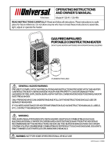
INSTRUCTIONS AND PARTS LIST
National-Riverside
Universal
Model 44-PH
SPC
ALL-PRO
MODEL SPC-44PH
ALL PURPOSE
PROPANE
HEATER
40,000 BTU/HR
SCHEU PRODUCTS COMPANY, INCORPORATED
Mail: P.O. Box 250, Upland, CA 91785
Plant: 8855 Baker Ave., Rancho Cucamonga, CA 91730
Telephone: 909 981-5343
Type of Gas.................For use with Propane Only
Input rating........................................40,000 BTU/hr
Manifold Pressure....................................11" W.C.
Orifice Size.................................................1.90mm
Max. Supply Inlet Pressure.........................100 psi
Min. Supply Inlet Pressure...............................5 psi
RETAIN THESE INSTRUCTIONS FOR FUTURE REFERENCE
INSTALLER - LEAVE THESE INSTRUCTIONS WITH CONSUMER
FOR YOUR SAFETY
Do not store or use gasoline or other flammable vapors and liquids in the vicinity of this
or any other appliance.
WARNING: For Outdoor Use Only
8339
September 2001

SAFETY PRECAUTIONS
1. Check the heater thoroughly for damage. DO NOT
operate a damaged heater.
2. DO NOT modify the heater or operate a heater which
has been modified from its original condition.
3. Use only propane gas.
4. Use only VAPOR WITHDRAWAL propane supply. If
there is any question about vapor withdrawal, ask your
propane dealer.
5. Never use the heater if the ballast weight is not assem-
bled onto the base. The base must be weighted to avoid
tipping.
6. Use only the hose and regulator assembly provided
with the heater. Inspect hose assembly before each
use of the heater. If there is excessive abrasion or
wear, or hose is cut, replace with hose assembly listed
on parts list before using heater.
7. This heater is for outdoor use only, even so make sure
that there is ample fresh air ventilation. Do not use in
buildings, garages or other enclosed spaces.
8. If at any time gas odor is detected, IMMEDIATELY
DISCONTINUE operation until the source of gas has
been located and corrected.
9. Install the heater such that it is not directly exposed to
water spray, rain and/or dripping water or wind.
10. Maintain minimum clearance to people or normal
combustible material (like paper) of 3 feet from top, 2
feet from the reflector.
11. Operate only on a stable, level surface.
12. Do not move, handle or service while hot or burning.
13. Use only in accordance with local codes or, in the
absence of local codes, with the National Fuel Gas Code
ANSI Z223.1.
14. Do not hang or attach clothing or any other combustible
materials from, on or near the heater.
15. Check control compartment burners and circulation air
passageways for free air passage, make sure that there
are no obstructions. These areas are a common location
for spider webs, which can present a dangerous condi-
tion, damage the heater and render it unsafe for use. The
heater must be checked if any of the following conditions
exist:
a) Gas smell along with predominate yellow tipping of
the burner flames.
b) Heater does not reach temperature.
c) Uneven burner glow.
d) Burner makes popping noises during normal use,
other than during shutdown.
16. Care must be taken for the supervision of children in the
vicinity of an operating heater.
17. Due to high surface termperatures adults and children
must observe clearances to avoid burns or clothing
ignition.
headache
dizziness
burning eyes and nose
nausea
dry mouth or sore throat
So, be sure to follow advice about ventilation in these operating
instructions.
OPERATING INFORMATION
This is a propane, direct-fired heater.
Propane is heavier than air. If propane leaks from a connection
or fitting, it sinks to the floor, collecting there with the
surrounding air, forming a potentially explosive mixture. Ob-
viously, propane leaks should be avoided, so set up the
propane supply with utmost care. Leak check new connec-
tions or reconnections with a soap and water solution and
follow all connection instructions herein. Also, ask your
propane dealer for advice on the propane supply installation
and ask him to check it if there are any questions.
Direct-fired means that all of the combustion products enter
the heated space. Even though this heater operates very
close to 100 percent combustion efficiency, it still produces
small amounts of carbon monoxide. Carbon monoxide (called
CO) is toxic.
CO can build up in a heated space and failure to provide
adequate ventilation could result in death. The symptoms of
inadequate ventilation are:
WARNING: FIRE, BURN, INHALATION, AND EX-
PLOSION HAZARD. KEEP SOLID COMBUSTIBLES, SUCH
AS BUILDING MATERIALS, PAPER OR CARDBOARD, A
SAFE DISTANCE AWAY FROM THE HEATER AS RECOM-
MENDED BY THE INSTRUCTIONS. NEVER USE THE HEATER
IN SPACES WHICH DO OR MAY CONTAIN VOLATILE OR
AIRBORNE COMBUSTIBLES, OR PRODUCTS SUCH AS
GASOLINE, SOLVENTS, PAINT THINNER, DUST PARTICLES
OR UNKNOWN CHEMICALS.
!
FOR YOUR SAFETY
If you smell gas:
1. Shut off gas to the appliance.
2. Extinguish any open flame.
3. If odor continues, immediately call
your gas supplier.
Tools Required
8 mm Socket and Driver or Screwdriver
#2 & #3 Philips Head Screwdriver
Open End Wrenches: 10mm, 11mm, 12mm, 3/4"
Teflon Tape - Pipe Thread Sealer
Page 2

NOTE: Assembly of this heater requires basic
mechanical skills. Proper assembly is the
responsibility of the installer Installation and
repair should be done by a qualified service
person.
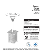
STEP 1:
Attach the three base support legs on the base using three (3)
M6-1.25 x 20mm hex head bolts, three (3) M6 lock washers,
six (6) flat washers, and three (3) M6-1.25 nuts.
STEP 2:
Place the ballast weight plate under the base. Tighten the
weight and base together using four (4) M6-1.25 x 25mm hex
head bolts, four (4) M6 lock washers, eight (8) M6 flat washers
and four (4) M6-1.25 nuts.
STEP 3:
Place the post support on the base support legs (see figure 1).
Tighten the post support and the base support legs together
using six (6) M6-1.25 x 20mm hex head bolts, six (6) M6 lock
washers, twelve (12) M6 flat washers, and six (6) M6-1.25 nuts.
NOTE: Make sure that all bolts are tightened before proceed-
ing to the next assembly step.
Figure 1: Step 1, 2 & 3
STEP 4:
Slide the cylinder cover over the base module assembled
in the previous steps. See figure 2.
ASSEMBLY INSTRUCTIONS
Figure 2: Step 4
GAS REQUIREMENTS
The heater comes with a regulator/hose assembly for
hook-up to a standard 20 pound LP gas tank (18- 1.4" high,
12- 1/4" diameter). The LP tank is not included. A
dented or rusty LP tank may be hazardous and
should be checked by your LP supplier. Never use an
LP tank with a damaged valve. The LP tank must be
arranged to provide for vapor withdrawal from the operating
cylinder. Never connect an unregulated LP tank to the
heater. The heater is shipped from the factory for LP use,
never substitute gases
LP Gas Hook-up:
The heater is designed to house a 20 pound gas cylinder
in the base assembly. Lift the cylinder cover, and place the
LP cylinder into the housing. The regulator can then be
screwed into the LP cylinder, the regulator and the tank
have right-handed threads (clockwise to tighten. No teflon
tape is required). When tightening be careful not to put too
much force on the LP cylinder valve.
Page 3

STEP 5:
Remove one protective end cap from the end of the fuel line
with the male pipe thread. Wrap the male pipe threads with
Teflon tape (not included). Set the burner assembly on a flat
surface. Screw the gas line into the main burner inlet fitting
and tighten using a ¾” wrench. Make sure that the
connection between the gas line and the main burner inlet
fitting is tight. See figure 3.
Figure 3: Step 5
STEP 6:
Slide the post over the fuel line. Push the post over the lower
end of the main burner housing. The post end with the three
holes goes first. Attach the post to the main burner using
three (3) M6 lock washers, three (3) M6 flat washers, and
M6 phillips head screws. See figure 4.
Figure 4: Step 6
Page 4

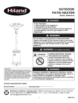
STEP 7:
Carefully insert the post into the post support socket (base
assembly) and make sure that the lower end of the fuel line
passes through the hole in the post support plate. Using
three (3) M6-1.25 setscrews secure the post into the
support socket with the supplied Allen wrench. Make sure
that the setscrews firmly grip the post. See figure 5.
STEP 8:
Secure the reflector onto the three reflector brackets on the
burner assembly using three (3) M8-1.5 hex nuts and three (3)
M8 washers. Make sure that the nuts are tight before moving
on to step 9. See figure 6.
Figure 5: Step 7
Figure 6: Step 8
STEP 9:
Carefully lift up the cylinder cover. Tilt the cylinder cover bottom
and set its bottom edge onto the post support plate. Make sure
that the cylinder cover is at the stable position. Remove the other
protective end cap from the fuel line inlet fitting. Hold the fuel line
inlet fitting with an
3
/
4
” wrench and tighten the hose & regulator
assembly onto the fuel line inlet fitting with another ¾” wrench.
See figure 7.
STEP 10:
Lower the cylinder cover down to cover the cylinder compartment.
Figure 7: Step 9 & 10
NOTE: Make sure that patio heater stands vertically. If it does
not slightly loosen the setscrews, then retighten them
after making corrections. All fuel connections must be
checked for leaks, using a soap and water solution,
upon initial operation of the heater.
Page 5

GENERAL INFORMATION
During use, liquid propane in a container vaporizes. As it vapor-
izes, the propane cools itself. If this cooling process continues
long enough and proceeds fast enough, the propane tempera-
ture and pressure will fall so low that heater operation may be
improper or even impossible even though plenty of propane
remains in the container. Often frost forms on the outside of the
propane container as a warning of excessive refrigeration.
Recommendations to reduce the ill effects of refrigeration are:
- Provide considerably more propane than you plan to
consume. As a rule of thumb, provide twice as much.
- Fill containers frequently, especially in cold weather.
Never allow propane to fall below one-third of container
capacity.
- If possible, keep containers in a warm area. Under no
circumstances should a heater exhaust be directed
toward the propane cylinder.
OPERATING INSTRUCTIONS
FUEL CONNECTION:
1) Use a 20-pound (5-gallon) vapor withdrawal propane
cylinder. Not supplied with the heater.
2) Place the cylinder in the heater base with the valve
accessible.
3) Connect the POL fitting of the hose & regulator
assembly to the propane cylinder by rotating the
plastic POL nut clockwise into the propane cylinder’s
valve outlet and securely tighten.
4) Make sure that the safety valve is turned off then open
the cylinder’s valve and check all gas connections
with a soap and water solution. DO NOT USE A
FLAME. The gas connections to check include those
in the heater base and the connections in the burner
assembly.
∆∆
∆∆
∆ CAUTION
When the heater is to be operated in the presence of other
people the user is responsible for properly acquainting those
present with safety precautions, and other hazards involved.
START:
1) Lift the Cylinder cover on the base, and set it on top of
the post socket plate.
2) Check all propane connections as described in the
fuel connection section of this manual.
3) Fully open the valve on the propane cylinder.
4) Turn the safety valve control knob to pilot.
5) Push and hold the control knob then push and release
the ignition button repeatedly until there is a flame at
the pilot. If the ignition button does not work the pilot
can be match-lit through the access hole, found under
the emitter base.
6) Continue to hold the gas valve control knob depressed
for 30 seconds after pilot ignition, then release.
7) Turn the burner on to maximum rate then reduce to
desired setting.
8) Lower the cylinder cover onto the base to cover the
propane cylinder.
STOP:
1) Turn the gas valve control knob to “off’ position.
2) If heater is not to be used, securely close the valve at
the propane cylinder.
3) Do not attempt to relight the heater for 5 minutes,
after the propane cylinder valve has been closed.
RESTART AFTER SHUTDOWN:
1) Turn the gas valve control knob to the “off’ position.
2) Wait 5 minutes.
3) Restart following “start” procedure.
MAINTENANCE AND STORAGE:
1) A qualified person should inspect the heater before
each use, and at least annually.
2) Before each use, check the POL fitting for any
damage, and replace if any damage is found.
3) Turn off the propane vapor supply at the cylinder
when the heater is not to be used.
4) Spiders and insects can nest and live in outdoor
appliances, especially in the burners and orifices.
This will interrupt the normal flow of LP-gas to the
heater and can be a very dangerous situation. The
heater must be inspected for insect infiltration of the
burner / orifice annually, or when one of the following
occur:
a. Gas smell along with predominate yellow
tipping of the burner flames.
b. Heater does not reach temperature.
c. Uneven burner glow.
d. Burner makes popping noises during
normal use, other than during shutdown.
5) When the heater is to be stored indoors, the connec-
tion between the LP-gas supply cylinder and the
heater must be disconnected and the cylinder
removed from the heater and stored in accordance
with chapter 5 of the standard for Storage and Hand-
ling of Liquefied Petroleum Gases ANSI/NFPA 58.
WARNING:
Local codes for installation of propane systems may vary
considerably. Therefore, ask you local propane supplier for
advice on propane system installation in you particular area.
In the absence of local codes, install in accordance with
American National Standards Institute (ANSI)/National Fire
Protection Assocation (NFPA) publication “Standard for
the Storage and Handling of Liquified Petroleum Gases
ANSI/NFPA 58 and National Fuel Gas Code ANSI Z223.1.”
Your propane supplier, fire marshal or library should have a
copy.
The propane supply system must be arranged for vapor
withdrawal. Propane cylinders must be secured in the
base and chained in the upright position to keep them from
falling or being knocked over.
Page 6

INSTRUCTIONS FOR ORDERING PARTS -
All parts orders must show Heater Model No., Item No., Part
No. and Description. We recommend that only parts supplied
by the manufacturer be used on this unit. A locally purchased
part may appear to be identical, although in reality it might
endanger the heater or the persons operating the heater.
The heater should be serviced only by a trained, experienced
service person. Read the section on "Servicing" before
ordering parts.
For parts order, call (909) 981-5343 or visit our website at
www.scheuco.com.
PARTS LIST
Part
Item No. Description Qty.
Part
Item No. Description Qty.
SERVICING
A hazardous condition may result if a heater is used that has
been modified or is not functioning properly. When the heater
is working properly:
* The flame is contained within the heater.
* The flame is essentially blue.
* There is no strong disagreeable odor, eye
burning or other physical discomfort.
* There is no smoke or soot internal or external to
the heater.
* There are no unplanned or unexplained shut
downs of the heater.
The parts list shows the heater as it was constructed. Do not
use a heater which is different from that shown. In this regard,
use only the hose, regulator and cylinder connection fitting
(called a POL fitting) supplied with the heater. Do not use
alternates. For this heater, the regulator must be set to supply
11" W.C. outlet pressure. If there is any uncertainty about the
regulator setting, have it checked.
A heater which is not working right must be repaired, but only
by a trained, experienced service person. Contact the factory
for the service center closest to you, phone number (909) 981-
5343.
You may also obtain in-warranty or out-of-warranty service by
returning the product postage prepaid to:
Scheu Products Company
8855 Baker Avenue
Rancho Cucamonga, CA 91730
In-warranty products returned to the Service Department will
be repaired with no change for either parts or labor and will be
returned to you freight prepaid. Please include a brief state-
ment indicating date, place of purchase, the nature of the
problem and proof of purchase.
Out-of-warranty products returned to the Service Department
will be repaired with a charge for parts and labor and will be
returned to you freight collect.
1 8320 Dome (Reflector) 1 25 8301 Thermocouple 1
2 8235 Emitter 1 26 8303 Orifice 1
3 8314 Plate, Valve, Heat Shield 1 27 8305 Ignition Wire Shield 1
4 8321 Emitter Bottom 1 * 8339 Instruction Manual 1
5 8238 Pilot Cover 1 28 8262 Nut, Brass 1
6 8239 Burner 1 29 8263 Bolt, Dome Mounting 3
7 8240 Pilot 1 30 8264 Washer, Flat, 8mm, SS 6
8 8241 Valve Housing, Front 1 31 8319 Washer Lock 3
9 8242 Knob 1 32 8266 Nut, Hex Dome Support, SS 6
10 8243 Valve Support 1 33 8304 TE Valve 1
11 8244 View Hole Cover 1 34 8306 Pilot Orifice/Pilot Tube 1
12 8308 Fitting, TE Valve 1 35 8269 Screw, SS 23
13 8248 Fuel Line 1 36 8270 Screw, Burner to Tube, SS 3
14 8249 Valve Housing, Wrap 1 37 8302 Electrode 1
15 8250 Upper Post Connector 1 38 8272 Set Screw, Tube Mounting 3
16 8251 Piezo Igniter 1 39 8273 Screw, Base Assembly 9
17 8252 Post 1 40 8274 Washer Lock, Base Assembly 16
18 8253 Cylinder Cover 1 41 8275 Washer Flat, Base Assembly 29
19 8254 Post Support 1 42 8276 Nut, Hex, Base Assembly 16
20 2075 Hose & Regulator Assembly 1 43 8277 Bolt, Ballast Weight 4
21 8255 Legs, Base 3
22 8256 Base 1
23 8257 Ballast Weight 1
24 8258 Fuel Line, Fixed Plate 1
Page 8
* Not Shown

Page 7
/