Fluke 3000 FC General Maintenance System User manual
- Category
- Multimeters
- Type
- User manual

July 2014
© 2014 Fluke Corporation. All rights reserved. Specifications are subject to change without notice.
All product names are trademarks of their respective companies.
3000 FC
Wireless Multimeter
Calibration Manual

LIMITED WARRANTY AND LIMITATION OF LIABILITY
Each Fluke product is warranted to be free from defects in material and workmanship under normal use and
service. The warranty period is three years and begins on the date of shipment. Parts, product repairs, and
services are warranted for 90 days. This warranty extends only to the original buyer or end-user customer of
a Fluke authorized reseller, and does not apply to fuses, disposable batteries, or to any product which, in
Fluke's opinion, has been misused, altered, neglected, contaminated, or damaged by accident or abnormal
conditions of operation or handling. Fluke warrants that software will operate substantially in accordance
with its functional specifications for 90 days and that it has been properly recorded on non-defective media.
Fluke does not warrant that software will be error free or operate without interruption.
Fluke authorized resellers shall extend this warranty on new and unused products to end-user customers
only but have no authority to extend a greater or different warranty on behalf of Fluke. Warranty support is
available only if product is purchased through a Fluke authorized sales outlet or Buyer has paid the
applicable international price. Fluke reserves the right to invoice Buyer for importation costs of
repair/replacement parts when product purchased in one country is submitted for repair in another country.
Fluke's warranty obligation is limited, at Fluke's option, to refund of the purchase price, free of charge repair,
or replacement of a defective product which is returned to a Fluke authorized service center within the
warranty period.
To obtain warranty service, contact your nearest Fluke authorized service center to obtain return
authorization information, then send the product to that service center, with a description of the difficulty,
postage and insurance prepaid (FOB Destination). Fluke assumes no risk for damage in transit. Following
warranty repair, the product will be returned to Buyer, transportation prepaid (FOB Destination). If Fluke
determines that failure was caused by neglect, misuse, contamination, alteration, accident, or abnormal
condition of operation or handling, including overvoltage failures caused by use outside the product’s
specified rating, or normal wear and tear of mechanical components, Fluke will provide an estimate of repair
costs and obtain authorization before commencing the work. Following repair, the product will be returned to
the Buyer transportation prepaid and the Buyer will be billed for the repair and return transportation charges
(FOB Shipping Point).
THIS WARRANTY IS BUYER'S SOLE AND EXCLUSIVE REMEDY AND IS IN LIEU OF ALL OTHER
WARRANTIES, EXPRESS OR IMPLIED, INCLUDING BUT NOT LIMITED TO ANY IMPLIED WARRANTY
OF MERCHANTABILITY OR FITNESS FOR A PARTICULAR PURPOSE. FLUKE SHALL NOT BE LIABLE
FOR ANY SPECIAL, INDIRECT, INCIDENTAL OR CONSEQUENTIAL DAMAGES OR LOSSES,
INCLUDING LOSS OF DATA, ARISING FROM ANY CAUSE OR THEORY.
Since some countries or states do not allow limitation of the term of an implied warranty, or exclusion or
limitation of incidental or consequential damages, the limitations and exclusions of this warranty may not
apply to every buyer. If any provision of this Warranty is held invalid or unenforceable by a court or other
decision-maker of competent jurisdiction, such holding will not affect the validity or enforceability of any other
provision.
Fluke Corporation
P.O. Box 9090
Everett, WA 98206-9090
U.S.A.
Fluke Europe B.V.
P.O. Box 1186
5602 BD Eindhoven
The Netherlands
11/99

i
Table of Contents
Title Page
Introduction ........................................................................................................ 1
Contact Fluke ..................................................................................................... 1
Safety Information .............................................................................................. 2
Symbols ......................................................................................................... 4
Hazardous Voltage ........................................................................................ 4
Test Lead Alert .............................................................................................. 4
Specifications ..................................................................................................... 5
AC Voltage ..................................................................................................... 6
DC Voltage, Continuity, Resistance, Diode Test, and Capacitance .............. 6
AC and DC Current ........................................................................................ 6
Frequency ...................................................................................................... 7
Frequency Counter Sensitivity ....................................................................... 7
Input Characteristics ...................................................................................... 7
MIN MAX Recording ...................................................................................... 7
Required Equipment .......................................................................................... 8
Performance Tests ............................................................................................. 9
Display Test ................................................................................................... 9
Backlight Test ................................................................................................ 9
Keypad Test ................................................................................................... 9
Fuse Test ....................................................................................................... 10
Function Performance Tests ......................................................................... 11
Before Calibration Adjustment ........................................................................... 14
Enter the Password ....................................................................................... 14
Change the Password ................................................................................... 14
Restore the Default Password ....................................................................... 15
Calibration Adjustment ....................................................................................... 16
Maintenance ....................................................................................................... 18
User-Replaceable Parts ..................................................................................... 20

3000 FC
Calibration Manual
ii

iii
List of Tables
Table Title Page
1. Symbols .................................................................................................................. 4
2. Required Equipment ............................................................................................... 8
3. Performance Tests ................................................................................................. 12
4. Calibration Adjustment ........................................................................................... 17
5. User-Replaceable Parts ......................................................................................... 20

3000 FC
Calibration Manual
iv

v
List of Figures
Figure Title Page
1. Fuse Test ................................................................................................................ 10
2. Non-Current Performance Test Connections ......................................................... 11
3. Current Performance Test Connections ................................................................. 12
4. Calibration Password Reset ................................................................................... 15
5. Battery and Fuse Replacement .............................................................................. 19
6. Replacement Parts and Accessories ..................................................................... 21

3000 FC
Calibration Manual
vi

1
Introduction
Warning
To prevent possible electrical shock, fire, or personal injury,
read all safety information before you use the Product.
This manual contains the verification and calibration adjustment procedures for
the 3000 FC Wireless Multimeter (the Product). Please see the 3000 FC Users
Manual for usage information.
Contact Fluke
To contact Fluke, call one of the following telephone numbers:
• Technical Support USA: 1-800-44-FLUKE (1-800-443-5853)
• Calibration/Repair USA: 1-888-99-FLUKE (1-888-993-5853)
• Canada: 1-800-36-FLUKE (1-800-363-5853)
• Europe: +31 402-675-200
• Japan: +81-3-6714-3114
• Singapore: +65-6799-5566
• Anywhere in the world: +1-425-446-5500
Or, visit Fluke's website at www.fluke.com.
To register your product, visit http://register.fluke.com.
To view, print, or download the latest manual supplement, visit
http://us.fluke.com/usen/support/manuals.

3000 FC
Calibration Manual
2
Safety Information
A Warning identifies conditions and procedures that are dangerous to the user.
A Caution identifies conditions and procedures that can cause damage to the
Product or the equipment under test.
Warning
To prevent possible electrical shock, fire, or personal injury:
• Carefully read all instructions.
• Use the Product only as specified, or the protection supplied by the
Product can be compromised.
• Limit operation to the specified measurement category, voltage, or
amperage ratings.
• Do not use the Product around explosive gas, vapor, or in damp or
wet environments.
• Do not touch voltages >30 V ac rms, 42 V ac peak, or 60 V dc.
• Do not exceed the Measurement Category (CAT) rating of the lowest
rated individual component of a Product, probe, or accessory.
• Measure a known voltage first to make sure that the Product
operates correctly.
• Do not use the Product if it is damaged.
• Disable the Product if it is damaged.
• Do not work alone.
• Disconnect power and discharge all high-voltage capacitors before
you measure resistance, continuity, capacitance, or a diode
junction.
• Comply with local and national safety codes. Use personal
protective equipment (approved rubber gloves, face protection, and
flame-resistant clothes) to prevent shock and arc blast injury where
hazardous live conductors are exposed.
• Remove circuit power before you connect the Product in the circuit
when you measure current. Connect the Product in series with the
circuit.
• Limit operation to the specified measurement category, voltage, or
amperage ratings.
• Have an approved technician repair the Product.
• Do not operate the Product with covers removed or the case open.
Hazardous voltage exposure is possible.
• Use only specified replacement parts.
• Remove the input signals before you clean the Product.
• Replace the batteries when the low battery indicator shows to
prevent incorrect measurements.
• The battery door must be closed and locked before you operate the
Product.
• Remove the test leads and all input signals before you replace the
batteries or fuses.

Wireless Multimeter
Safety Information
3
• Do not use the Product if it operates incorrectly.
• Examine the case before you use the Product. Look for cracks or
missing plastic. Carefully look at the insulation around the
terminals.
• Use only correct measurement category (CAT), voltage, and
amperage rated probes, test leads, and adapters for the
measurement.
• Do not use test leads if they are damaged. Examine the test leads
for damaged insulation, exposed metal, or if the wear indicator
shows. Check test lead continuity.
• Keep fingers behind the finger guards on the probes.
• Do not touch the probes to a voltage source when the test leads are
connected to the current terminals.
• Replace a blown fuse with exact replacement only for continued
protection against arc flash.
• Remove the batteries if the Product is not used for an extended
period of time, or if stored in temperatures above 50 °C. If the
batteries are not removed, battery leakage can damage the Product.
• Batteries contain hazardous chemicals that can cause burns or
explode. If exposure to chemicals occurs, clean with water and get
medical aid.
• Connect the common test lead before the live test lead and remove
the live test lead before the common test lead.
• Remove all probes, test leads, and accessories that are not
necessary for the measurement.
• Do not use the TL175 or TP175 test probes in CAT III or CAT IV
environments without the probe tip fully extended and correct
category rating visible in the window.
• When the TL175 is used with instruments or other accessories, the
lowest category rating of the combination applies. One exception is
when the probe is used with the AC172 or AC175.
• Make sure test leads are firmly connected to instrument and
other accessories.

3000 FC
Calibration Manual
4
Symbols
The symbols in Table 1 are used on the Product or in this manual.
Table 1. Symbols
Symbol Meaning
Risk of Danger. Important information. See Manual.
Conforms to European Union directives.
Conforms to relevant North American Safety Standards.
Battery
Hazardous voltage.
Conforms to relevant Australian EMC requirements.
Fuse
Conforms to relevant South Korean EMC standards.
CAT III
Measurement Category III is applicable to test and measuring circuits connected to the
distribution part of the building’s low-voltage MAINS installation.
CAT IV
Measurement Category IV is applicable to test and measuring circuits connected at the
source of the building’s low-voltage MAINS installation.
Double Insulation
This product complies with the WEEE Directive (2002/96/EC) marking requirements. The
affixed label indicates that you must not discard this electrical/electronic product in
domestic household waste. Product Category: With reference to the equipment types in the
WEEE Directive Annex I, this product is classed as category 9 "Monitoring and Control
Instrumentation" product. Do not dispose of this product as unsorted municipal waste. Go
to Fluke’s website for recycling information.
Hazardous Voltage
The display shows and the hazardous voltage indicator illuminates red when a
hazardous voltage (≥30 V) is present on the input of the Product
Test Lead Alert
The display shows LEAD for a second when you turn the function switch to or
from the mA position to remind you to make sure the test leads are in the correct
terminals.

Wireless Multimeter
Specifications
5
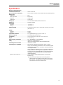
Specifications
Maximum voltage between any
Terminal and Earth Ground ................................. 1000 V dc or ac rms
Fuse Protection for mA inputs ....................... 0.44 A (44/100 A, 440 mA), 1000 V FAST Fuse, Fluke specified part only
Display (LCD)
Update rate ......................................................... 4/sec
Votls, amps, ohms, ............................................. 6,000 counts
Frequency ........................................................... 10,000 counts
Capacitance ........................................................ 1,000 counts
Battery Type .......................................................... Three AA Alkaline batteries, NEDA 15A IEC LR6
Battery Life ............................................................ 250 hours minimum
Temperature
Operating ............................................................ -10 °C to 50 °C
Storage ............................................................... -40 °C to 60 °C
Relative Humidity .................................................. 0 % to 90 % (0 °C to 35 °C), 0 % to 75 % (35 °C to 40 °C), 0 % to 45 %
(40 °C to 50 °C)
Altitude
Operating ............................................................ 2,000 m
Storage ............................................................... 12,000 m
Temperature Coefficient ....................................... 0.1 X (specified accuracy) /°C (<18 °C or >28 °C)
Wireless Frequency .............................................. 2.4 GHz ISM Band 20 meter range
Size (HxWxL) ......................................................... 1.87 in x 3.68 in x 8.14 in (4.75 cm x 9.3 cm x 20.7 cm)
Weight .................................................................... 17.2 oz (487.5 g)
Radio Frequency Certification ............................. FCC: T68-DMFBLE; IC: 6627A-DMFBLE
Safety ..................................................................... IEC 61010-1, Pollution Degree 2
IEC 61010-2-033:Measurement 1000V CAT III/600V CATIV
Electromagnetic Environment ............................. IEC 61236-1, Portable
Electromagnetic Compatibility ............................ Radio Frequency Emissions, IEC CISPR 11: Group 1, Class A.
Group 1 have intentionally generated and/or use conductively coupled
radio-frequency energy which is necessary for the internal functioning
of the equipment itself.
Class A equipment is suitable for use in non-domestic locations and/or
directly connected to a low-voltage power supply network. Class A
equipment may have potential difficulties in ensuring electromagnetic
compatibility in other environments due to conducted as well as
radiated disturbances.
Applies to use in Korea only. .............................. Class A Equipment (Industrial Broadcasting & Communication
Equipment) [1]
[1] This product meets requirements for industrial (Class A)
electromagnetic wave equipment and the seller or user should
take notice of it. This equipment is intended for use in business
environments and is not to be used in homes.

3000 FC
Calibration Manual
6
For all specifications:
Accuracy is specified for 1 year after calibration, at operating temperatures of 18 °C to 28 °C, with relative humidity at 0 %
to 90 %. Accuracy specifications take the form of ±([ % of Reading ] + [ Number of least significant digits ]).
AC Voltage
Function
Range
[1]
Resolution
Accuracy
[2][3][4]
45 Hz to 500 Hz 500 Hz to 1 kHz
600.0 mV 0.1 mV
1.0 % + 3 2.0 % + 3
6.000 V 0.001 V
60.00 V 0.01 V
600.0 V 0.1 V
1000 V 1 V
[1] All ac voltage ranges are specified from 1 % of range to 100 % of range.
[2] Crest factor of ≤3 at 4000 counts, decreasing linearly to 1.5 at full scale.
[3] For non-sinusoidal waveforms, add –(2 % of reading + 2 % full scale) typical, for crest factor up to 3.
[4] Do not exceed 10
7
V-Hz
DC Voltage, Continuity, Resistance, Diode Test, and Capacitance
Function Range Resolution Accuracy
600.0 mV 0.1 mV 0.09 % + 2
6.000 V 0.001 V
0.09 % + 2
60.00 V 0.01 V
600.0 V 0.1 V
1000 V 1 V 0.15 % + 2
600 Ω 1 Ω
Meter beeps at <25 Ω, beeper detects opens or shorts of
250 μs or longer.
Ω
600.0 Ω 0.1 Ω
0.5 % + 2
6.000 kΩ 0.001 kΩ
0.5 % + 1
60.00 kΩ 0.01 kΩ
600.0 kΩ 0.1 kΩ
6.000 MΩ 0.001 MΩ
50.00 MΩ 0.01 MΩ
1.5 % + 3
Diode Test 2.000 V 0.001 V 1 % + 2
1000 nF 1 nF
1.2 % + 2
10.00 μF 0.01 μF
100.0 μF 0.1 μF
9999 μF
[1]
1 μF
10 % typical
[1] In the 9999 μF range for measurements to 1000 μF, the measurement accuracy is 1.2 % + 2.
AC and DC Current
Function
Range
[1]
Resolution
Accuracy
(45 Hz to 1 kHZ)
60.00 mA 0.01 mA
1.5 % + 3
400.0 mA
[3]
0.1 mA
[2]
60.00 mA 0.01 mA
0.5 % + 3
400.0 mA
[3]
0.1 mA
[1] All ac current ranges are specified from 5 % of range to 100 % of range.
[2] Input burden voltage (typical): 400 mA input 2 mV/mA.
[3] 400.0 mA accuracy specified up to 600 mA overload.

Wireless Multimeter
Specifications
7
Frequency
Range Resolution
Accuracy
[1]
99.99 Hz 0.01 Hz
0.1 % + 1
999.9 Hz 0.1 Hz
9.999 kHz 0.001 kHz
99.99 kHz 0.01 kHz
[1] Frequency is specified up to 99.99 kHz in volts and up to 10 kHz in amps.
Frequency Counter Sensitivity
Input Range
[1] [2]
Typical Sensitivity (RMS Sine Wave)
2 Hz to 45 Hz 45 Hz to 10 kHz 10 kHz to 20 kHz 20 kHz to 50 kHz 50 kHz to 100 kHz
6 V 0.5 V 0.6 V 1.0 V 2.8 V Unspecified
[3]
60 V 5 V 3.8 V 4.1 V 5.6 V 9.6 V
600 V 50 V 36 V 39 V 50 V 58 V
1000 V 500 V 300 V 320 V 380 V NA
6 V 0.5 V 0.75 V 1.4 V 4.0 V Unspecified
[3]
60 V 4 V 3.8 V 4.3 V 6.6 V 13 V
600 V 40 V 36 V 39 V 45 V 58 V
1000 V 500 V 300 V 320 V 380 V NA
60.00 mA 5 mA 4 mA NA NA NA
400.0 mA 5 mA 4 mA NA NA NA
[1] Maximum input for specified accuracy = 10X Range or 1000 V.
[2] Noise at low frequency and amplitude may exceed the frequency accuracy specification.
[3] Unspecified but usable depending on quality and amplitude of signal.
[4] In mA and A ranges, frequency measurement is specified to 10 kHz.
Input Characteristics
Function
Overload
Protection
Input Impedance
(nominal)
Common Mode
Rejection Ratio
(1 kΩ unbalance)
Normal Mode Rejection
1100 V rms
>10 MΩ <100 pF
> 120 dB at dc, 50 Hz or 60 Hz > 60 dB at 50 Hz or 60 Hz
1100 V rms
>10 MΩ < 100 pF
> 60 dB, dc to 60 Hz
1100 V rms
>10 MΩ <100 pF
> 120 dB at dc, 50 Hz or 60 Hz > 60 dB at 50 Hz or 60 Hz
Open Circuit Test
Voltage
Full Scale Voltage
Typical Short Circuit Current
To 6 MΩ 50 MΩ
Ω /
1100 V rms <2.7 V dc <0.7 V dc <0.9 V dc
<350 μA
/
1100 V rms <2.7 V dc 2.000 V dc <1.1 mA
Function Overload Protection
Overload
mA Fused, 44/100 A, 1000 V FAST Fuse 600 mA overload for 2 minutes maximum, 10 minutes rest
minimum
MIN MAX Recording
Function Accuracy
DC Functions
The specified accuracy of the measurement function ±12 counts for changes >350 ms in duration.
AC Functions
The specified accuracy of the measurement function ±40 counts for changes >900 ms in duration.

3000 FC
Calibration Manual
8
Required Equipment
The equipment in Table 2 is necessary for performance tests and calibration
adjustment.
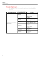
Table 2. Required Equipment
Recommended Equipment Measurement Function Accuracy
5522A Multi-Product Calibrator
(or equivalent)
DC Volts
10 mV to 600 V
±0.02 %
DC Current
600 μA to 10 A
±0.25 %
AC Volts
6 mV to 600 V
±0.25 % @ 45 Hz to 1 kHz
AC Current
600 µA to 10 A
±0.375 % @ 45 Hz to 1 kHz
Resistance
0 Ω to 5 MΩ
±0.225 %
10 Ω to 30 MΩ
±0.375 %
Capacitance
9 μF to 900 μF
±0.475 %
Frequency
2 V @ 50 kHz
±0.025 %

Wireless Multimeter
Performance Tests
9
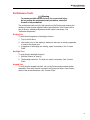
Performance Tests
Warning
To prevent possible electrical shock, fire, or personal injury,
do not perform the performance test procedures unless the
Product is fully assembled.
The performance tests verify the full operation of the Product and measure the
accuracy of each function against Product specifications. If the Product fails a
part of the test, calibration adjustment and/or repair is necessary. See
“Calibration Adjustment”.
Display Test
To verify that all segments of the display function:
1. Turn on the Product.
2. Look at the icons on the display to make sure there are no missing segments
or voids in the display text.
3. If segments of the display are missing, repair is necessary. See “Contact
Fluke”.
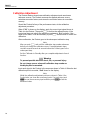
Backlight Test
To verify that the backlight functions:
1. With the Product on, push .
2. The backlight comes on. If it does not, repair is necessary. See “Contact
Fluke”.
Keypad Test
To verify that the keypad functions, turn on the Product and push each button
separately. Each time a button is pushed, the Product will beep. If the Product
does not act as described here, see “Contact Fluke”.

3000 FC
Calibration Manual
10
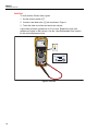
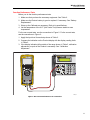
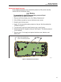
Fuse Test
To verify that the Product fuse is good:
1. Set the function switch to
.
2. Connect a test lead to the
jack as shown in Figure 1.
3. Touch the other end of the test lead to the mA jack.
A good fuse will show a resistance of 12 Ω or less. Replace the fuse if the
resistance is higher or OL is shown. See the “User-Replaceable Parts” section
for the correct replacement fuse.
440 mA
<12
OK
OK
gxr009.eps
Figure 1. Fuse Test

Wireless Multimeter
Performance Tests
11
Function Performance Tests
Before you do the function performance tests:
1. Make sure that you have the necessary equipment. See Table 2.
2. Make sure the Product battery is good or replace it if necessary. See “Battery
Replacement”.
3. Warm up the Calibrator as necessary. Refer to its specifications.
4. Let the temperature of the UUT (Unit Under Test) become stable to room
temperature.
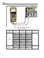
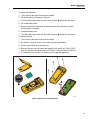
For the non-current tests, see the connections in Figure 2. For the current tests,
see the connections in Figure 3:
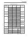
1. Apply the input level for each step shown in Table 3.
2. Compare the indication on the Product display with the display reading limits
in Table 3.
3. If the display indication falls outside of the range shown in Table 3, calibration
adjustment or repair of the Product is necessary. See “Calibration
Adjustment”.
0
•
/
+
5522A
HI
LO
TC
1000V
RM S
MAX
20V
RM S
MAX
20V
PK
MAX
1V PK
MAX
20V PK
MAX
NORMAL AUX
TRIG
OUT
SCOPE
V, ,
RTD
A, -SENSE,
AUX V
150V PK
MAX
20V PK
MAX
3000 FC
hcd07.eps
Figure 2. Non-Current Performance Test Connections

3000 FC
Calibration Manual
12
0
•
/
+
5522A
HI
LO
TC
1000V
RM S
MAX
20V
RM S
MAX
20V
PK
MAX
1V PK
MAX
20V PK
MAX
NORMAL AUX
TRIG
OUT
SCOPE
V, ,
RTD
A, -SENSE,
AUX V
150V PK
MAX
20V PK
MAX
3000 FC
hcd09.eps
Figure 3. Current Performance Test Connections
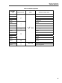
Table 3. Performance Tests
Test
(Switch
Position)
Input Lower Limit Upper Limit Units
Volts AC
5 V 45 Hz 4.947 5.053
V ac
5 V 1 kHz 4.897 5.103
3 V 45 Hz 2.967 3.033
50 V 45 Hz 49.47 50.53
50 V 1 KHz 48.97 51.03
30 V 45 Hz 29.67 30.33
500 V 45 Hz 494.7 505.3
500 V 1 kHz 489.7 510.3
1000 V 45 Hz 987 1013
Volts AC,
Frequency
1 V 900 Hz 899.0 901.0
Hz
5 V 50 kHz 49.94 50.06
Page is loading ...
Page is loading ...
Page is loading ...
Page is loading ...
Page is loading ...
Page is loading ...
Page is loading ...
Page is loading ...
Page is loading ...
Page is loading ...
-
 1
1
-
 2
2
-
 3
3
-
 4
4
-
 5
5
-
 6
6
-
 7
7
-
 8
8
-
 9
9
-
 10
10
-
 11
11
-
 12
12
-
 13
13
-
 14
14
-
 15
15
-
 16
16
-
 17
17
-
 18
18
-
 19
19
-
 20
20
-
 21
21
-
 22
22
-
 23
23
-
 24
24
-
 25
25
-
 26
26
-
 27
27
-
 28
28
-
 29
29
-
 30
30


Fluke 3000 FC General Maintenance System User manual
- Category
- Multimeters
- Type
- User manual
Ask a question and I''ll find the answer in the document
Finding information in a document is now easier with AI
Related papers
-
Fluke FLUKE-IR3000FC Product information
-
Fluke 3000 FC generelt vedligeholdelsessystem User guide
-
-
Fluke v3000 FC Wireless AC Voltage Kit User manual
-
-
-
Fluke Multímetro digital True-RMS 175 User manual
-
-
Fluke v3000 FC Wireless AC Voltage Kit User manual
-
Other documents
-
FLULKE Digital Multimeter User manual
-
Black Box FLUKE-179 Datasheet
-
Fluke Calibration 9190A User manual
-
 Fluke networks Fluke Networks MT-8200-49A Copper Tester User manual
-
SIGLENT SHS800 Series Handheld Digital Oscilloscope User guide
-
-
Promax FP-2 User manual
-
Tektronix DMM830 User manual
-
-
Megger AVO410 User manual
