ASROCK H77 Pro4/MVP Owner's manual
- Category
- Motherboards
- Type
- Owner's manual

1
ASRock H77M-ITX Motherboard
English
Copyright Notice:
No part of this installation guide may be reproduced, transcribed, transmitted, or trans-
lated in any language, in any form or by any means, except duplication of documentation
by the purchaser for backup purpose, without written consent of ASRock Inc.
Products and corporate names appearing in this guide may or may not be registered
trademarks or copyrights of their respective companies, and are used only for identica-
tion or explanation and to the owners’ benet, without intent to infringe.
Disclaimer:
Specications and information contained in this guide are furnished for informational use
only and subject to change without notice, and should not be constructed as a commit-
ment by ASRock. ASRock assumes no responsibility for any errors or omissions that may
appear in this guide.
With respect to the contents of this guide, ASRock does not provide warranty of any kind,
either expressed or implied, including but not limited to the implied warranties or condi-
tions of merchantability or tness for a particular purpose. In no event shall ASRock, its
directors, ofcers, employees, or agents be liable for any indirect, special, incidental, or
consequential damages (including damages for loss of prots, loss of business, loss of
data, interruption of business and the like), even if ASRock has been advised of the pos-
sibility of such damages arising from any defect or error in the guide or product.
This device complies with Part 15 of the FCC Rules. Operation is subject to the following
two conditions:
(1) this device may not cause harmful interference, and
(2) this device must accept any interference received, including interference that
may cause undesired operation.
CALIFORNIA, USA ONLY
The Lithium battery adopted on this motherboard contains Perchlorate, a toxic substance
controlled in Perchlorate Best Management Practices (BMP) regulations passed by the
California Legislature. When you discard the Lithium battery in California, USA, please
follow the related regulations in advance.
“Perchlorate Material-special handling may apply, see
www.dtsc.ca.gov/hazardouswaste/perchlorate”
ASRock Website: http://www.asrock.com
Published June 2013
Copyright
©
2013 ASRock INC. All rights reserved.

2
ASRock H77M-ITX Motherboard
English
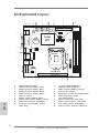
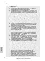
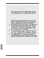
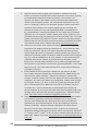
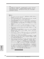
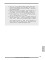
Motherboard Layout
1 SPI Flash Memory (64Mb)
2 SATA3 Connector (SATA_1, Gray)
3 SATA3 Connector (SATA_0, Gray)
4 SATA2 Connector (SATA_2, Black)
5 SATA2 Connector (SATA_3, Black)
6 Intel H77 Chipset
7 USB 2.0 Header (USB4_5, Black)
8 System Panel Header (PANEL1, Black)
9 ATX Power Connector (ATXPWR1)
10 Consumer Infrared Module Header
(CIR1, Gray)
11 2 x 240-pin DDR3 DIMM Slots
(DDR3_A1, DDR3_B1, Black)
12 USB 3.0 Header (USB3_3_4, Black)
13 1155-Pin CPU Socket
14 PCI Express 3.0 x16 Slot (PCIE1, Black)
15 Front Panel Audio Header
(HD_AUDIO1, Black)
16 CPU Fan Connector (CPU_FAN1)
17 Chassis Fan Connector (CHA_FAN1)
18 Clear CMOS Jumper (CLRCMOS1)
19 ATX 12V Power Connector (ATX12V1)
Intel
H77
H77M-ITX
Front USB 3.0
64Mb
BIOS
CMOS
Battery
17.0cm (6.7 in)
17.0 cm (6.7 in)
ATXPWR1
DDR3_A1 (64 bit, 240-pin module)
DDR3_B1 (64 bit, 240-pin module)
X
Fast RAM
PCI Express 3.0
PCIE1
Sup er
I/O
USB 2.0
T: US B0
B: USB1
PS2
Keyb oa rd
VGA1
DVI1
HDMI1
USB 2.0
T: USB2
B: USB 3
ESATA1
Top:
RJ-45
USB 3.0
T: U SB1
B: USB 2
Top:
CTR BA SS
Center:
REAR S PK
Bottom:
Optical
SPDIF
Top:
LINE I N
Center:
FRONT
Bottom:
MIC IN
AUD IO
COD EC
1
HD_ AU DIO 1
RoHS
DDR3
USB 4_5
1
CIR1
1
USB 3_3 _4
CHA _FA N1
CPU _FA N1
CLR CMO S1
1
HDLE D RES ET
PLED PWRBT N
PANEL 1
1
SATA_ 1
SATA_ 0
SATA_ 3
SATA_ 2
ATX1 2V 1
1
2
3
4 5
6
1 1
1 2
1 3
1 4
1 0
7
8
9
1 5
1 6
1 7
1 8
1 9

3
ASRock H77M-ITX Motherboard
English
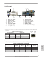
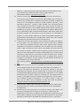
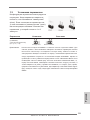
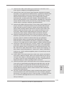
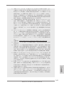
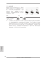
I/O Panel
* There are two LED next to the LAN port. Please refer to the table below for the LAN port LED
indications.
LAN Port LED Indications
Activity/Link LED SPEED LED
Status Description Status Description
Off No Link Off 10Mbps connection
Blinking Data Activity Orange 100Mbps connection
On Link Green 1Gbps connection
1 USB 2.0 Ports (USB01)
2 D-Sub Port (VGA1)
3 USB 2.0 Ports (USB23)
* 4 LAN RJ-45 Port
5 Central / Bass (Orange)
6 Rear Speaker (Black)
7 Line In (Light Blue)
** 8 Front Speaker (Lime)
ACT/LINK
LED
SPEED
LED
LAN Port
**
If you use 2-channel speaker, please connect the speaker’s plug into “Front Speaker Jack”.
See the table below for connection details in accordance with the type of speaker you use.
TABLE for Audio Output Connection
Audio Output Channels Front Speaker Rear Speaker Central / Bass Line in
(No. 8) (No. 6) (No. 5) (No. 7)
2 V -- -- --
4 V V -- --
6 V V V --
8 V V V V
1
2
3
4
5
10
6
7
8
9
11
13
12
14
15
9 Microphone (Pink)
10 Optical SPDIF Out Port
11 USB 3.0 Ports (USB3_12)
12 eSATA2 Connector
13 HDMI Port (HDMI1)
14 DVI-D Port (DVI1)
15 PS/2 Keyboard Port (Purple)

4
ASRock H77M-ITX Motherboard
English
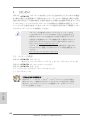
To enable Multi-Streaming function, you need to connect a front panel audio cable to the front
panel audio header. After restarting your computer, you will nd “Mixer” tool on your system.
Please select “Mixer ToolBox” , click “Enable playback multi-streaming”, and click
“ok”. Choose “2CH”, “4CH”, “6CH”, or “8CH” and then you are allowed to select “Realtek HDA
Primary output” to use Rear Speaker, Central/Bass, and Front Speaker, or select “Realtek
HDA Audio 2nd output” to use front panel audio.

5
ASRock H77M-ITX Motherboard
1. Introduction
Thank you for purchasing ASRock H77M-ITX motherboard, a reliable motherboard
produced under ASRock’s consistently stringent quality control. It delivers excellent
performance with robust design conforming to ASRock’s commitment to quality and
endurance.
This Quick Installation Guide contains introduction of the motherboard and step-by-
step installation guide. More detailed information of the motherboard can be found
in the user manual presented in the Support CD.
Because the motherboard specications and the BIOS software might be
updated, the content of this manual will be subject to change without no-
tice. In case any modications of this manual occur, the updated version
will be available on ASRock website without further notice. You may nd
the latest VGA cards and CPU support lists on ASRock website as well.
ASRock website http://www.asrock.com
If you require technical support related to this motherboard, please visit
our website for specic information about the model you are using.
www.asrock.com/support/index.asp
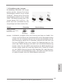
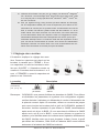
1.1 Package Contents
ASRock H77M-ITX Motherboard
(Mini-ITX Form Factor: 6.7-in x 6.7-in, 17.0 cm x 17.0 cm)
ASRock H77M-ITX Quick Installation Guide
ASRock H77M-ITX Support CD
2 x Serial ATA (SATA) Data Cables (Optional)
1 x I/O Panel Shield
English
ASRock Reminds You...
To get better performance in Windows
®
7 / 7 64-bit / Vista
TM
/ Vista
TM
64-
bit, it is recommended to set the BIOS option in Storage Conguration to
AHCI mode. For the BIOS setup, please refer to the “User Manual” in our
support CD for details.

6
ASRock H77M-ITX Motherboard
English
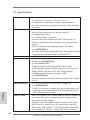
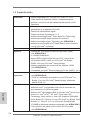
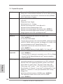
1.2 Specifications
Platform - Mini-ITX Form Factor: 6.7-in x 6.7-in, 17.0 cm x 17.0 cm
- All Solid Capacitor design (100% Japan-made high-quality
Conductive Polymer Capacitors)
CPU - Supports 3
rd
and 2
nd
Generation Intel
®
Core
TM
i7 / i5 / i3 in
LGA1155 Package
- Digi Power Design
- 4 + 2 Power Phase Design
- Supports Intel
®
Turbo Boost 2.0 Technology
- Supports Intel
®
K-Series unlocked CPU
- Supports Hyper-Threading Technology (see CAUTION 1)
- Supports Intel
®
Rapid Start Technology and Smart Connect
Technology with Intel
®
Ivy Bridge CPU
Chipset - Intel
®
H77
Memory - Dual Channel DDR3 Memory Technology (see CAUTION 2)
- 2 x DDR3 DIMM slots
- Supports DDR3 1600/1333/1066 non-ECC, un-buffered
memory (DDR3 1600 with Intel
®
Ivy Bridge CPU, DDR3
1333 with Intel
®
Sandy Bridge CPU)
- Max. capacity of system memory: 16GB (see CAUTION 3)
- Supports Intel
®
Extreme Memory Prole (XMP)1.3/1.2
Expansion Slot - 1 x PCI Express 3.0 x16 slot (PCIE1: x16 mode)
(see CAUTION 4)
* PCIE 3.0 is only supported with Intel
®
Ivy Bridge CPU. With
Intel
®
Sandy Bridge CPU, it only supports PCIE 2.0.
Graphics * Intel
®
HD Graphics Built-in Visuals and the VGA outputs can
be supported only with processors which are GPU
integrated.
- Supports Intel
®
HD Graphics Built-in Visuals: Intel
®
Quick
Sync Video 2.0, Intel
®
InTru
TM
3D, Intel
®
Clear Video HD
Technology, Intel
®
Insider
TM
, Intel
®
HD Graphics 2500/4000
- Pixel Shader 5.0, DirectX 11 with Intel
®
Ivy Bridge CPU.
Pixel Shader 4.1, DirectX 10.1 with Intel
®
Sandy Bridge
CPU.
- Max. shared memory 1760MB (see CAUTION 5)
- Three VGA Output options: D-Sub, DVI-D and HDMI
(see CAUTION 6)
- Supports HDMI 1.4a Technology with max. resolution up to
1920x1200 @ 60Hz

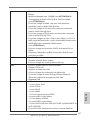
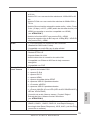
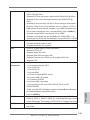
7
ASRock H77M-ITX Motherboard
English
- Supports DVI with max. resolution up to 1920x1200 @ 60Hz
- Supports D-Sub with max. resolution up to 2048x1536 @
75Hz
- Supports Auto Lip Sync, Deep Color (12bpc), xvYCC and
HBR (High Bit Rate Audio) with HDMI (Compliant HDMI
monitor is required) (see CAUTION 7)
- Supports HDCP function with DVI and HDMI ports
- Supports Full HD 1080p Blu-ray (BD) / HD-DVD playback
with DVI and HDMI ports
Audio - 7.1 CH HD Audio with Content Protection
(Realtek ALC892 Audio Codec)
- Premium Blu-ray audio support
LAN - PCIE x1 Gigabit LAN 10/100/1000 Mb/s
- Realtek RTL8111E
- Supports Wake-On-LAN
- Supports LAN Cable Detection
- Supports Energy Efcient Ethernet 802.3az
- Supports PXE
Rear Panel I/O I/O Panel
- 1 x PS/2 Keyboard Port
- 1 x D-Sub Port
- 1 x DVI-D Port
- 1 x HDMI Port
- 1 x Optical SPDIF Out Port
- 4 x Ready-to-Use USB 2.0 Ports
- 1 x eSATA2 Connector
- 2 x Ready-to-Use USB 3.0 Ports
- 1 x RJ-45 LAN Port with LED (ACT/LINK LED and SPEED
LED)
- HD Audio Jack: Rear Speaker/Central/Bass/Line in/Front
Speaker/Microphone (see CAUTION 8)
SATA3 - 2 x SATA3 6.0 Gb/s connectors, support RAID (RAID 0,
RAID 1, RAID 5, RAID 10, Intel Rapid Storage and Intel
Smart Response Technology), NCQ, AHCI and Hot Plug
functions
USB3.0 - 2 x Rear USB 3.0 ports, support USB 1.0/2.0/3.0 up to
5Gb/s
- 1 x Front USB 3.0 header (supports 2 USB 3.0 ports),
supports USB 1.0/2.0/3.0 up to 5Gb/s

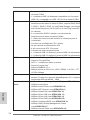
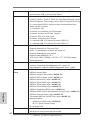
8
ASRock H77M-ITX Motherboard
English
Connector - 2 x SATA2 3.0 Gb/s connectors, support RAID (RAID 0,
RAID 1, RAID 5, RAID 10, Intel Rapid Storage and Intel
Smart Response Technology), NCQ, AHCI and Hot Plug
functions
- 2 x SATA3 6.0Gb/s connectors
- 1 x CIR header
- CPU/Chassis FAN connector
- 24 pin ATX power connector
- 4 pin 12V power connector
- Front panel audio connector
- 1 x USB 2.0 header (supports 2 USB 2.0 ports)
- 1 x USB 3.0 header (supports 2 USB 3.0 ports)
BIOS Feature - 64Mb AMI UEFI Legal BIOS with GUI support
- Supports “Plug and Play”
- ACPI 1.1 Compliance Wake Up Events
- Supports jumperfree
- SMBIOS 2.3.1 Support
- CPU Core, IGPU, DRAM, 1.8V PLL, VTT, VCCSA Voltage
Multi-adjustment
Support CD - Drivers, Utilities, AntiVirus Software (Trial Version),
CyberLink MediaEspresso 6.5 Trial, ASRock MAGIX
Multimedia Suite - OEM
Unique Feature - ASRock Extreme Tuning Utility (AXTU) (see CAUTION 9)
- ASRock Instant Boot
- ASRock Instant Flash (see CAUTION 10)
- ASRock APP Charger (see CAUTION 11)
- ASRock SmartView (see CAUTION 12)
- ASRock XFast USB (see CAUTION 13)
- ASRock XFast LAN (see CAUTION 14)
- ASRock XFast RAM (see CAUTION 15)
- ASRock Crashless BIOS (see CAUTION 16)
- ASRock OMG (Online Management Guard)
(see CAUTION 17)
- ASRock Internet Flash (see CAUTION 18)
- ASRock On/Off Play Technology (see CAUTION 19)
- Hybrid Booster:
- ASRock U-COP (see CAUTION 20)
- Boot Failure Guard (B.F.G.)
- Good Night LED
Hardware - CPU Temperature Sensing
Monitor - Chassis Temperature Sensing

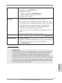
9
ASRock H77M-ITX Motherboard
English
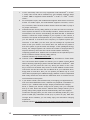
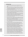
WARNING
Please realize that there is a certain risk involved with overclocking, including
adjusting the setting in the BIOS, applying Untied Overclocking Technology, or using
third-party overclocking tools. Overclocking may affect your system’s stability, or
even cause damage to the components and devices of your system. It should be
done at your own risk and expense. We are not responsible for possible damage
caused by overclocking.
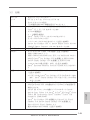
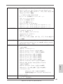
CAUTION!
1. About the settings of “Hyper Threading Technology”, please check page
43 of the “User Manual” in the support CD.
2. This motherboard supports Dual Channel Memory Technology. Before
you implement Dual Channel Memory Technology, make sure to read the
installation guide of memory modules on page 17 for proper installation.
3. Due to the operating system limitation, the actual memory size may be
less than 4GB for the reservation for system usage under Windows
®
7 /
Vista
TM
/ XP. For Windows
®
OS with 64-bit CPU, there is no such limita-
tion. You can use ASRock XFast RAM to utilize the memory that Win-
dows
®
cannot use.
4. To run the PCI Express in Gen 3 speed, please install an Ivy Bridge CPU.
If you install a Sandy Bridge CPU, the PCI Express will run only at PCI
Express Gen 2 speed.
5. The maximum shared memory size is dened by the chipset vendor and
is subject to change. Please check Intel
®
website for the latest informa-
tion.
6. You can choose to use two of the three monitors only. D-Sub, DVI-D and
HDMI monitors cannot be enabled at the same time. Besides, with the
DVI-to-HDMI adapter, the DVI-D port can support the same features as
HDMI port.
- CPU Fan Tachometer
- Chassis Fan Tachometer
- CPU/Chassis Quiet Fan (Allows Chassis Fan Speed Auto-
Adjust by CPU Temperature)
- CPU/Chassis Fan Multi-Speed Control
- Voltage Monitoring: +12V, +5V, +3.3V, CPU Vcore
OS - Microsoft
®
Windows
®
7 / 7 64-bit / Vista
TM
/ Vista
TM
64-bit /
XP / XP 64-bit compliant (see CAUTION 21)
Certications - FCC, CE, WHQL
- ErP/EuP Ready (ErP/EuP ready power supply is required)
(see CAUTION 22)
* For detailed product information, please visit our website: http://www.asrock.com

10
ASRock H77M-ITX Motherboard
English
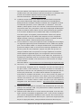
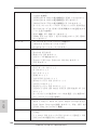
7. xvYCC and Deep Color are only supported under Windows
®
7 64-bit /
7. Deep Color mode will be enabled only if the display supports 12bpc
in EDID. HBR is supported under Windows
®
7 64-bit / 7 / Vista
TM
64-bit /
Vista
TM
.
8. For microphone input, this motherboard supports both stereo and mono
modes. For audio output, this motherboard supports 2-channel, 4-chan-
nel, 6-channel, and 8-channel modes. Please check the table on page 3
for proper connection.
9. ASRock Extreme Tuning Utility (AXTU) is an all-in-one tool to ne-tune dif-
ferent system functions in a user-friendly interface, which includes Hard-
ware Monitor, Fan Control, Overclocking, OC DNA and IES. In Hardware
Monitor, it shows the major readings of your system. In Fan Control, it
shows the fan speed and temperature for you to adjust. In Overclocking,
you are allowed to overclock CPU frequency for optimal system per-
formance. In OC DNA, you can save your OC settings as a prole and
share it with your friends. Your friends then can load the OC prole to
their own system to get the same OC settings. In IES (Intelligent Energy
Saver), the voltage regulator can reduce the number of output phases to
improve efciency when the CPU cores are idle without sacricing
computing performance. Please visit our website for the operation proce-
dures of ASRock Extreme Tuning Utility (AXTU).
ASRock website: http://www.asrock.com
10. ASRock Instant Flash is a BIOS ash utility embedded in Flash ROM.
This convenient BIOS update tool allows you to update system BIOS
without entering operating systems rst like MS-DOS or Windows
®
. With
this utility, you can press the <F6> key during the POST or the <F2>
key to enter into the BIOS setup menu to access ASRock Instant Flash.
Just launch this tool and save the new BIOS le to your USB ash drive,
oppy disk or hard drive, then you can update your BIOS only in a few
clicks without preparing an additional oppy diskette or other complicated
ash utility. Please be noted that the USB ash drive or hard drive must
use FAT32/16/12 le system.
11. If you desire a faster, less restricted way of charging your Apple devices,
such as iPhone/iPad/iPod Touch, ASRock has prepared a wonderful so-
lution for you - ASRock APP Charger. Simply install the APP Charger
driver, it makes your iPhone charge much quickly from your computer
and up to 40% faster than before. ASRock APP Charger allows you to
quickly charge many Apple devices simultaneously and even supports
continuous charging when your PC enters into Standby mode (S1), Sus-
pend to RAM (S3), hibernation mode (S4) or power off (S5). With APP
Charger driver installed, you can easily enjoy the marvelous charging
experience.
ASRock website: http://www.asrock.com/Feature/AppCharger/index.asp

11
ASRock H77M-ITX Motherboard
English
12. ASRock SmartView, a new function for internet browsers, is the smart
start page for IE that combines your most visited web sites, your history,
your Facebook friends and your real-time newsfeed into an enhanced
view for a more personal Internet experience. ASRock motherboards are
exclusively equipped with the ASRock SmartView utility that helps you
keep in touch with friends on-the-go. To use ASRock SmartView feature,
please make sure your OS version is Windows
®
7 / 7 64 bit / Vista
TM
/
Vista
TM
64 bit, and your browser version is IE8.
ASRock website: http://www.asrock.com/Feature/SmartView/index.asp
13. ASRock XFast USB can boost USB storage device performance. The
performance may depend on the properties of the device.
14. ASRock XFast LAN provides a faster internet access, which includes
the benets listed below. LAN Application Prioritization: You can cong-
ure your application’s priority ideally and/or add new programs. Lower
Latency in Game: After setting online game’s priority higher, it can lower
the latency in games. Trafc Shaping: You can watch Youtube HD videos
and download simultaneously. Real-Time Analysis of Your Data: With
the status window, you can easily recognize which data streams you are
transferring currently.
15. ASRock XFast RAM is a new function that is included into ASRock Ex-
treme Tuning Utility (AXTU). It fully utilizes the memory space that cannot
be used under Windows
®
OS 32-bit CPU. ASRock XFast RAM shortens
the loading time of previously visited websites, making web surng faster
than ever. And it also boosts the speed of Adobe Photoshop 5 times
faster. Another advantage of ASRock XFast RAM is that it reduces the
frequency of accessing your SSDs or HDDs in order to extend their lifes-
pan.
16. ASRock Crashless BIOS allows users to update their BIOS without fear
of failing. If power loss occurs during the BIOS update process, ASRock
Crashless BIOS will automatically nish the BIOS update procedure after
regaining power. Please note that BIOS les need to be placed in the
root directory of your USB disk. Only USB2.0 ports support this feature.
17. Administrators are able to establish an internet curfew or restrict internet
access at specied times via OMG. You may choose from [Everyday], [Day
of the week] or [Weekdays and weekends], then schedule the starting
and ending hours of internet access granted to other users. In order to
prevent users from bypassing OMG, guest accounts without permission
to modify the system time are required.
18. ASRock Internet Flash searches for available UEFI firmware updates
from our servers. In other words, the system can auto-detect the latest
UEFI from our servers and ash them without entering Windows
®
OS.
Please note that you must be running on a DHCP congured computer in
order to enable this function.

12
ASRock H77M-ITX Motherboard
English
19. ASRock On/Off Play Technology allows users to enjoy the great audio
experience from the portable audio devices, such like MP3 player or
mobile phone to your PC, even when the PC is turned off (or in ACPI S5
mode)! This motherboard also provides a free 3.5mm audio cable (op-
tional) that ensures users the most convenient computing environment.
20. While CPU overheat is detected, the system will automatically shutdown.
Before you resume the system, please check if the CPU fan on the moth-
erboard functions properly and unplug the power cord, then plug it back
again. To improve heat dissipation, remember to spray thermal grease
between the CPU and the heatsink when you install the PC system.
21. ASRock XFast RAM is not supported by Microsoft
®
Windows
®
XP / XP
64-bit. Intel
®
Smart Connect Technology and Intel
®
USB 3.0 ports are not
supported by Microsoft
®
Windows
®
Vista
TM
/ Vista
TM
64-bit / XP / XP 64-
bit.
22. EuP stands for Energy Using Product, was a provision regulated by the
European Union to define the power consumption for the completed
system. According to EuP, the total AC power of the completed system
should be under 1.00W in off mode condition. To meet EuP standards,
an EuP ready motherboard and an EuP ready power supply are required.
According to Intel’s suggestion, the EuP ready power supply must meet
the standard of 5v, and the standby power efciency should be higher
than 50% under 100 mA current consumption. For EuP ready power sup-
ply selection, we recommend you to check with the power supply manu-
facturer for more details.

13
ASRock H77M-ITX Motherboard
English
2. Installation
This is a Mini-ITX form factor (6.7” x 6.7”, 17.0 x 17.0 cm) motherboard. Before you
install the motherboard, study the conguration of your chassis to ensure that the
motherboard ts into it.
Make sure to unplug the power cord before installing or removing the
motherboard. Failure to do so may cause physical injuries to you and
damages to motherboard components.
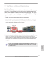
2.1 Screw Holes
Place screws into the holes indicated by circles to secure the motherboard to the
chassis.
Do not over-tighten the screws! Doing so may damage the motherboard.
2.2 Pre-installation Precautions
Take note of the following precautions before you install motherboard components
or change any motherboard settings.
1. Unplug the power cord from the wall socket before touching any
components.
2. To avoid damaging the motherboard’s components due to static
electricity, NEVER place your motherboard directly on the carpet
or the like. Also remember to use a grounded wrist strap or touch a
safety grounded object before you handle the components.
3. Hold components by the edges and do not touch the ICs.
4. Whenever you uninstall any component, place it on a grounded anti-
static pad or in the bag that comes with the component.
5. When placing screws into the screw holes to secure the mother-
board to the chassis, please do not over-tighten the screws! Doing
so may damage the motherboard.
Before you install or remove any component, ensure that the power is
switched off or the power cord is detached from the power supply. Failure to do
so may cause severe damage to the motherboard, peripherals, and/or
components.

14
ASRock H77M-ITX Motherboard
English
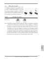
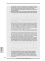
1155-Pin Socket Overview
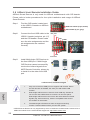
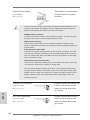
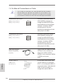
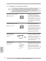
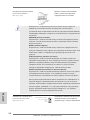
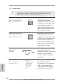
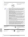
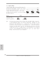
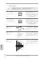
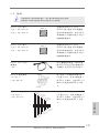
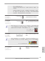
2.3 CPU Installation
In order to provide the LGA 1155 CPU sock-
ets more protection and make the instal-
lation process easier, ASRock has added
a new protection cover on top of the load
plate to replace the former PnP caps that
were under the load plate. For the installa-
tion of Intel
®
1155-Pin CPUs with the new
protection cover, please follow the steps
below.
Before you insert the 1155-Pin CPU into the socket, please check if the
CPU surface is unclean or if there are any bent pins in the socket. Do
not force to insert the CPU into the socket if above situation is found.
Otherwise, the CPU will be seriously damaged.
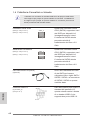
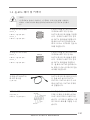
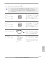
Step 1. Open the socket:
Step 1-1. Disengage the lever by pressing it
down and sliding it out of the hook.
You do not have to remove the pro-
tection cover.
Step 1-2. Keep the lever positioned at about
135 degrees in order to flip up the
load plate.
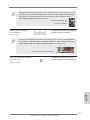
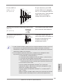
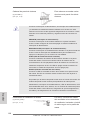
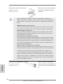
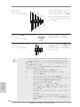
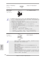
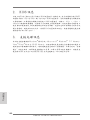
Step 2. Insert the 1155-Pin CPU:
Step 2-1. Hold the CPU by the edge which is
marked with a black line.
Step 2-2. Orient the CPU with the IHS (Inte-
grated Heat Sink) up. Locate Pin1
and the two orientation key notches.
Load
Plate
Cover
Contact
Array
Load
Lever
Socket
Body
black line

15
ASRock H77M-ITX Motherboard
English
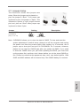
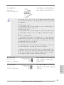
Pin1
alignment key
alignment key
Pin1
1155-Pin CPU
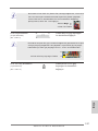
For proper installation, please ensure to match the two orientation
key notches of the CPU with the two alignment keys of the socket.
Step 2-3. Carefully place the CPU into the
socket.
Step 2-4. Verify that the CPU is within the sock-
et and properly mated to the orient
keys.
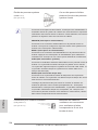
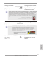
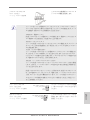
Step 3. Close the socket:
Step 3-1. Flip the load plate onto the IHS.
Step 3-2. Press down the load lever, and se-
cure it with the load plate tab under
the retention tab. The protection
cover will automatically come off by
itself.
Please save and replace the cover if the processor is removed. The
cover must be placed if you wish to return the motherboard for after
service.
orientation key notch
orientation key notch
1155-Pin Socket

16
ASRock H77M-ITX Motherboard
English
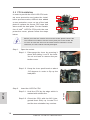
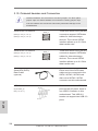
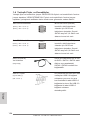
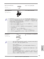
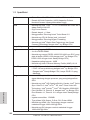
2.4 Installation of CPU Fan and Heatsink
This motherboard is equipped with 1155-Pin socket that supports Intel 1155-Pin
CPUs. Please adopt the type of heatsink and cooling fan compliant with Intel 1155-
Pin CPU to dissipate heat. Before you install the heatsink, you need to spray ther-
mal interface material between the CPU and the heatsink to improve heat dissipa-
tion. Ensure that the CPU and the heatsink are securely fastened and in good con-
tact with each other. Then connect the CPU fan to the CPU_FAN connector (CPU_
FAN1, see page 2, No. 16).
For proper installation, please kindly refer to the instruction manuals of your
CPU fan and heatsink.
Below is an example to illustrate the installation of the heatsink for 1155-Pin CPUs.
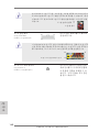
Step 1. Apply thermal interface material onto the cen-
ter of the IHS on the socket’s surface.
Step 2. Place the heatsink onto the socket. Ensure
that the fan cables are oriented on side closest
to the CPU fan connector on the motherboard
(CPU_FAN1, see page 2, No. 16).
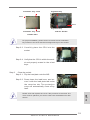
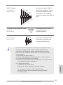
Step 3. Align fasteners with the motherboard through-
holes.
Step 4. Rotate the fastener clockwise, then press
down on fastener caps with thumb to install
and lock. Repeat with remaining fasteners.
If you press down the fasteners without rotating them clockwise, the
heatsink cannot be secured on the motherboard.
Step 5. Connect fan header with the CPU fan connector on the motherboard.
Step 6. Secure redundant cable with tie-wrap to ensure the cable does not
interfere with fan operation or contact other components.
Apply Th er m al
Interface Ma ter ial
Fan ca bl e s on side
close st to MB header
Faste ner slots
point ing straight ou t
Press Down
(4 Pl a ces)

17
ASRock H77M-ITX Motherboard
English
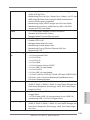
2.5 Installation of Memory Modules (DIMM)
This motherboard provides two 240-pin DDR3 (Double Data Rate 3) DIMM slots,
and supports Dual Channel Memory Technology. For dual channel configuration,
you always need to install two identical (the same brand, speed, size and chip-
type) memory modules in the DDR3 DIMM slots to activate Dual Channel Memory
Technology. Otherwise, it will operate at single channel mode.
1. It is not allowed to install a DDR or DDR2 memory module into
DDR3 slot;otherwise, this motherboard and DIMM may be
damaged.
2. If you install only one memory module or two non-identical
memory modules, it is unable to activate the Dual Channel
Memory Technology.
3. Some DDR3 1GB double-sided DIMMs with 16 chips may not
work on this motherboard. It is not recommended to install them
on this motherboard.
Installing a DIMM
Please make sure to disconnect power supply before adding or
removing DIMMs or the system components.
Step 1. Unlock a DIMM slot by pressing the retaining clips outward.
Step 2. Align a DIMM on the slot such that the notch on the DIMM matches the
break on the slot.
The DIMM only ts in one correct orientation. It will cause permanent
damage to the motherboard and the DIMM if you force the DIMM into
the slot at incorrect orientation.
Step 3. Firmly insert the DIMM into the slot until the retaining clips at both ends
fully snap back in place and the DIMM is properly seated.
notch
break
notch
break

18
ASRock H77M-ITX Motherboard
English
2.6 Expansion Slot (PCI Express Slot)
There is 1 PCI Express slot on this motherboard.
PCIE slots: PCIE1 (PCIE 3.0 x16 slot) is used for PCI Express x16 lane width
graphics cards.
To run the PCI Express in Gen 3 speed, please install an Ivy Bridge
CPU. If you install a Sandy Bridge CPU, the PCI Express will run only at
PCI Express Gen 2 speed.
Installing an expansion card
Step 1. Before installing an expansion card, please make sure that the power
supply is switched off or the power cord is unplugged. Please read the
documentation of the expansion card and make necessary hardware
settings for the card before you start the installation.
Step 2. Remove the system unit cover (if your motherboard is already installed
in a chassis).
Step 3. Remove the bracket facing the slot that you intend to use. Keep the
screws for later use.
Step 4. Align the card connector with the slot and press rmly until the card is
completely seated on the slot.
Step 5. Fasten the card to the chassis with screws.
Step 6. Replace the system cover.

19
ASRock H77M-ITX Motherboard
English
2. If you have already installed the onboard VGA driver from our support CD to your
system, you can freely enjoy the benets of dual monitor function after your
system boots. If you haven’t installed the onboard VGA driver yet, please install
the onboard VGA driver from our support CD to your system and restart your
computer.
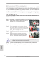
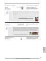
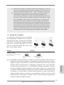
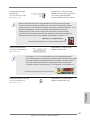
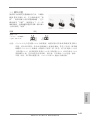
2.7 Dual Monitor and Surround Display Features
Dual Monitor Feature
This motherboard supports dual monitor feature. With the internal VGA output sup-
port (DVI-D, D-Sub and HDMI), you can easily enjoy the benets of dual monitor
feature without installing any add-on VGA cards to this motherboard. This mother-
board also provides independent display controllers for DVI-D, D-Sub and HDMI to
support dual VGA output so that DVI-D, D-sub and HDMI can drive same or different
display contents.
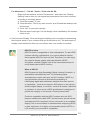
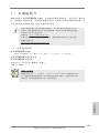
To enable dual monitor feature, please follow the steps below:
1. Connect a DVI-D monitor cable to the DVI-D port on the I/O panel, connect a
D-Sub monitor cable to the D-Sub port on the I/O panel and connect a HDMI
monitor cable to the HDMI port on the I/O panel.
HDMI port
D-Sub port
DVI-D port
D-Sub, DVI-D and HDMI monitors cannot be enabled at the same time.
You can only choose the combination: DVI-D + HDMI, DVI-D + D-Sub,
or HDMI + D-Sub.

20
ASRock H77M-ITX Motherboard
English
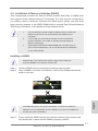
Surround Display Feature
This motherboard supports surround display upgrade. With the internal VGA output
support (DVI-D, D-Sub and HDMI) and external add-on PCI Express VGA cards,
you can easily enjoy the benets of surround display feature.
Please refer to the following steps to set up a surround display environment:
1. Install the PCI Express VGA cards on PCIE1 slot. Please refer to page 18 for
proper expansion card installation procedures.
2. Connect a DVI-D monitor cable to the DVI-D port on the I/O panel, connect a
D-Sub monitor cable to the D-Sub port on the I/O panel and connect a HDMI
monitor cable to the HDMI port on the I/O panel. Then connect other monitor
cables to the corresponding connectors of the add-on PCI Express VGA cards on
PCIE1 slot.
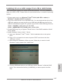
3. Boot your system. Press <F2> or <Del> to enter UEFI setup. Enter “Share
Memory” option to adjust the memory capability to [32MB], [64MB], [128MB],
[256MB] or [512MB] to enable the function of D-sub. Please make sure that the
value you select is less than the total capability of the system memory. If you do
not adjust the UEFI setup, the default value of “Share Memory”, [Auto], will
disable D-Sub function when an add-on VGA card is inserted to this motherboard.
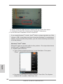
4. Install the onboard VGA driver and the add-on PCI Express VGA card driver to
your system. If you have installed the drivers already, there is no need to install
them again.
5. Set up a multi-monitor display.
For Windows
®
XP / XP 64-bit OS:
Right click on desktop, choose “Properties”, and select the “Settings” tab
so that you can adjust the parameters of the multi-monitors according to
the steps below.
A. Click the “Identify” button to display a large number on each monitor.
B. Right-click the display icon in the Display Properties dialog that you
wish to be your primary monitor, and then select “Primary”. When
you use multiple monitors with your card, one monitor will always be
Primary, and all additional monitors will be designated as Secondary.
C. Select the display icon identied by the number 2.
D. Click “Extend my Windows desktop onto this monitor”.
E. Right-click the display icon and select “Attached”, if necessary.
F. Set the appropriate “Screen Resolution” and “Color Quality” for the
second monitor. Click “Apply” or “OK” to apply these new values.
G. Repeat steps C through E for the display icon identied by the
numbers three to four.
Page is loading ...
Page is loading ...
Page is loading ...
Page is loading ...
Page is loading ...
Page is loading ...
Page is loading ...
Page is loading ...
Page is loading ...
Page is loading ...
Page is loading ...
Page is loading ...
Page is loading ...
Page is loading ...
Page is loading ...
Page is loading ...
Page is loading ...
Page is loading ...
Page is loading ...
Page is loading ...
Page is loading ...
Page is loading ...
Page is loading ...
Page is loading ...
Page is loading ...
Page is loading ...
Page is loading ...
Page is loading ...
Page is loading ...
Page is loading ...
Page is loading ...
Page is loading ...
Page is loading ...
Page is loading ...
Page is loading ...
Page is loading ...
Page is loading ...
Page is loading ...
Page is loading ...
Page is loading ...
Page is loading ...
Page is loading ...
Page is loading ...
Page is loading ...
Page is loading ...
Page is loading ...
Page is loading ...
Page is loading ...
Page is loading ...
Page is loading ...
Page is loading ...
Page is loading ...
Page is loading ...
Page is loading ...
Page is loading ...
Page is loading ...
Page is loading ...
Page is loading ...
Page is loading ...
Page is loading ...
Page is loading ...
Page is loading ...
Page is loading ...
Page is loading ...
Page is loading ...
Page is loading ...
Page is loading ...
Page is loading ...
Page is loading ...
Page is loading ...
Page is loading ...
Page is loading ...
Page is loading ...
Page is loading ...
Page is loading ...
Page is loading ...
Page is loading ...
Page is loading ...
Page is loading ...
Page is loading ...
Page is loading ...
Page is loading ...
Page is loading ...
Page is loading ...
Page is loading ...
Page is loading ...
Page is loading ...
Page is loading ...
Page is loading ...
Page is loading ...
Page is loading ...
Page is loading ...
Page is loading ...
Page is loading ...
Page is loading ...
Page is loading ...
Page is loading ...
Page is loading ...
Page is loading ...
Page is loading ...
Page is loading ...
Page is loading ...
Page is loading ...
Page is loading ...
Page is loading ...
Page is loading ...
Page is loading ...
Page is loading ...
Page is loading ...
Page is loading ...
Page is loading ...
Page is loading ...
Page is loading ...
Page is loading ...
Page is loading ...
Page is loading ...
Page is loading ...
Page is loading ...
Page is loading ...
Page is loading ...
Page is loading ...
Page is loading ...
Page is loading ...
Page is loading ...
Page is loading ...
Page is loading ...
Page is loading ...
Page is loading ...
Page is loading ...
Page is loading ...
Page is loading ...
Page is loading ...
Page is loading ...
Page is loading ...
Page is loading ...
Page is loading ...
Page is loading ...
Page is loading ...
Page is loading ...
Page is loading ...
Page is loading ...
Page is loading ...
Page is loading ...
Page is loading ...
Page is loading ...
Page is loading ...
Page is loading ...
Page is loading ...
Page is loading ...
Page is loading ...
Page is loading ...
Page is loading ...
Page is loading ...
Page is loading ...
Page is loading ...
Page is loading ...
Page is loading ...
Page is loading ...
Page is loading ...
Page is loading ...
Page is loading ...
Page is loading ...
Page is loading ...
Page is loading ...
Page is loading ...
Page is loading ...
Page is loading ...
Page is loading ...
Page is loading ...
Page is loading ...
-
 1
1
-
 2
2
-
 3
3
-
 4
4
-
 5
5
-
 6
6
-
 7
7
-
 8
8
-
 9
9
-
 10
10
-
 11
11
-
 12
12
-
 13
13
-
 14
14
-
 15
15
-
 16
16
-
 17
17
-
 18
18
-
 19
19
-
 20
20
-
 21
21
-
 22
22
-
 23
23
-
 24
24
-
 25
25
-
 26
26
-
 27
27
-
 28
28
-
 29
29
-
 30
30
-
 31
31
-
 32
32
-
 33
33
-
 34
34
-
 35
35
-
 36
36
-
 37
37
-
 38
38
-
 39
39
-
 40
40
-
 41
41
-
 42
42
-
 43
43
-
 44
44
-
 45
45
-
 46
46
-
 47
47
-
 48
48
-
 49
49
-
 50
50
-
 51
51
-
 52
52
-
 53
53
-
 54
54
-
 55
55
-
 56
56
-
 57
57
-
 58
58
-
 59
59
-
 60
60
-
 61
61
-
 62
62
-
 63
63
-
 64
64
-
 65
65
-
 66
66
-
 67
67
-
 68
68
-
 69
69
-
 70
70
-
 71
71
-
 72
72
-
 73
73
-
 74
74
-
 75
75
-
 76
76
-
 77
77
-
 78
78
-
 79
79
-
 80
80
-
 81
81
-
 82
82
-
 83
83
-
 84
84
-
 85
85
-
 86
86
-
 87
87
-
 88
88
-
 89
89
-
 90
90
-
 91
91
-
 92
92
-
 93
93
-
 94
94
-
 95
95
-
 96
96
-
 97
97
-
 98
98
-
 99
99
-
 100
100
-
 101
101
-
 102
102
-
 103
103
-
 104
104
-
 105
105
-
 106
106
-
 107
107
-
 108
108
-
 109
109
-
 110
110
-
 111
111
-
 112
112
-
 113
113
-
 114
114
-
 115
115
-
 116
116
-
 117
117
-
 118
118
-
 119
119
-
 120
120
-
 121
121
-
 122
122
-
 123
123
-
 124
124
-
 125
125
-
 126
126
-
 127
127
-
 128
128
-
 129
129
-
 130
130
-
 131
131
-
 132
132
-
 133
133
-
 134
134
-
 135
135
-
 136
136
-
 137
137
-
 138
138
-
 139
139
-
 140
140
-
 141
141
-
 142
142
-
 143
143
-
 144
144
-
 145
145
-
 146
146
-
 147
147
-
 148
148
-
 149
149
-
 150
150
-
 151
151
-
 152
152
-
 153
153
-
 154
154
-
 155
155
-
 156
156
-
 157
157
-
 158
158
-
 159
159
-
 160
160
-
 161
161
-
 162
162
-
 163
163
-
 164
164
-
 165
165
-
 166
166
-
 167
167
-
 168
168
-
 169
169
-
 170
170
-
 171
171
-
 172
172
-
 173
173
-
 174
174
-
 175
175
-
 176
176
-
 177
177
-
 178
178
-
 179
179
-
 180
180
-
 181
181
-
 182
182
-
 183
183
-
 184
184
-
 185
185
-
 186
186
-
 187
187
-
 188
188
-
 189
189
-
 190
190


ASROCK H77 Pro4/MVP Owner's manual
- Category
- Motherboards
- Type
- Owner's manual
Ask a question and I''ll find the answer in the document
Finding information in a document is now easier with AI
in other languages
- italiano: ASROCK H77 Pro4/MVP Manuale del proprietario
- français: ASROCK H77 Pro4/MVP Le manuel du propriétaire
- español: ASROCK H77 Pro4/MVP El manual del propietario
- Deutsch: ASROCK H77 Pro4/MVP Bedienungsanleitung
- русский: ASROCK H77 Pro4/MVP Инструкция по применению
- português: ASROCK H77 Pro4/MVP Manual do proprietário
- Türkçe: ASROCK H77 Pro4/MVP El kitabı
- 日本語: ASROCK H77 Pro4/MVP 取扱説明書
Related papers
-
ASROCK Z77M Owner's manual
-
ASROCK H77WS-DL Owner's manual
-
-
-
-
ASROCK H77M-ITX + PCI-EXP-USB-V3 User manual
-
ASROCK H71M-DGS User manual
-
ASROCK H61TM-ITX Owner's manual
-
ASROCK ZH77 Pro3 User manual
-
ASROCK Z77E-ITX User manual
Other documents
-
Satechi Satechi Aluminum Type-C Dual HDMI Adapter 4K 60Hz User guide
-
Gigabyte GA-H77M-HD3 Owner's manual
-
-
Foxconn H77M-S User manual
-
Giada MI-H61C Datasheet
-
Vantec UGT-CR945 Installation guide
-
Blackmagicdesign SmartView Duo User manual
-
Akasa Cypher (non branded) User manual
-
Akasa InterConnect S User manual
-
Intenso 3.5" 4TB Owner's manual