Schumacher SEM-1562A User manual
- Category
- Battery chargers
- Type
- User manual
This manual is also suitable for

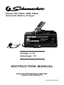
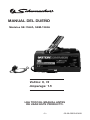
Models SE-1562A, SEM-1562A
Automatic Battery Charger
INSTRUCTION MANUAL
00-99-000254/0408
Voltage: 6, 12
Amperage: 1.5
READ ENTIRE MANUAL BEFORE
USING THIS PRODUCT
Page is loading ...

• 1 •
IMPORTANT SAFETY INSTRUCTIONS1.
SAVE THESE INSTRUCTIONS – This manual contains important safety 1.1
and operating instructions for battery charger Models SE-1562A and SEM-
1562A.
Do not expose charger to rain or snow.1.2
Use of an attachment not recommended or sold by the battery charger 1.3
manufacturer may result in a risk of re, electric shock, or injury to per-
sons.
To reduce risk of damage to electric plug and cord, pull by plug rather than 1.4
cord when disconnecting charger.
An extension cord should not be used unless absolutely necessary. Use of 1.5
improper extension cord could result in a risk of re and electric shock. If
an extension cord must be used, make sure:
That pins on plug of extension cord are the same number, size, and •
shape as those of plug on charger;
That extension cord is properly wired and in good electrical condition and;•
That wire size is large enough for AC ampere rating of charger as speci-•
ed in Table 8.2.
Do not operate charger with damaged cord or plug; take to a qualied 1.6
service person. (Call customer service at: 800-621-5485.)
Do not operate charger if it has received a sharp blow, been dropped, or 1.7
otherwise damaged in any way; take it to a qualied serviceman. (Call
customer service at: 800-621-5485.)
Do not disassemble charger; take it to a qualied serviceman when 1.8
service or repair is required. Incorrect reassembly may result in a risk of
electric shock or re. (Call customer service at: 800-621-5485.)
To reduce risk of electric shock, unplug charger from outlet before attempt-1.9
ing any maintenance or cleaning. Turning off controls will not reduce this
risk.
WARNING – RISK OF EXPLOSIVE GASES.
WORKING IN VICINITY OF A LEAD-ACID BATTERY IS DANGEROUS.
BATTERIES GENERATE EXPLOSIVE GASES DURING NORMAL
BATTERY OPERATION. FOR THIS REASON, IT IS OF UTMOST
IMPORTANCE THAT YOU FOLLOW THE INSTRUCTIONS EACH TIME
YOU USE THE CHARGER.
TO REDUCE RISK OF BATTERY EXPLOSION, FOLLOW THESE
INSTRUCTIONS AND THOSE PUBLISHED BY BATTERY MANUFAC-
TURER AND MANUFACTURER OF ANY EqUIPMENT YOU INTEND TO
USE IN VICINITY OF BATTERY. REVIEW CAUTIONARY MARKING ON
THESE PRODUCTS AND ON ENGINE.
IMPORTANT: READ AND SAVE THIS SAFETY AND INSTRUCTION MANUAL.

• 2 •
PERSONAL PRECAUTIONS2.
Consider having someone close enough by to come to your aid when you 2.1
work near a lead-acid battery.
Have plenty of fresh water and soap nearby in case battery acid contacts 2.2
skin, clothing, or eyes.
Wear complete eye protection and clothing protection. Avoid touching 2.3
eyes while working near battery.
If battery acid contacts skin or clothing, wash immediately with soap and 2.4
water. If acid enters eye, immediately ood eye with running cold water for
at least 10 minutes and get medical attention immediately.
NEVER smoke or allow a spark or ame in vicinity of battery or engine.2.5
Be extra cautious to reduce risk of dropping a metal tool onto battery. It 2.6
might spark or short-circuit battery or other electrical part that may cause
explosion.
Remove personal metal items such as rings, bracelets, necklaces, and 2.7
watches when working with a lead-acid battery. A lead-acid battery can
produce a short-circuit current high enough to weld a ring or the like to
metal, causing a severe burn.
Use charger for charging a LEAD-ACID battery only. It is not intended to 2.8
supply power to a low voltage electrical system other than in a starter-mo-
tor application. Do not use battery charger for charging dry-cell batteries
that are commonly used with home appliances. These batteries may burst
and cause injury to persons and damage to property.
NEVER charge a frozen battery.2.9
PREPARING TO CHARGE3.
If necessary to remove battery from vehicle to charge, always remove 3.1
grounded terminal from battery rst. Make sure all accessories in the
vehicle are off, so as not to cause an arc.
Be sure area around battery is well ventilated while battery is being 3.2
charged.
Clean battery terminals. Be careful to keep corrosion from coming in con-3.3
tact with eyes.
Add distilled water in each cell until battery acid reaches level specied by 3.4
battery manufacturer. Do not overll. For a battery without removable cell
caps, such as valve regulated lead acid batteries, carefully follow manu-
facturer’s recharging instructions.
Study all battery manufacturer’s specic precautions while charging and 3.5
recommended rates of charge.
Determine voltage of battery by referring to vehicle owner’s manual and 3.6
make sure that output voltage selector switch is set at correct voltage. If
charger has adjustable charge rate, charge battery initially at lowest rate.

• 3 •
CHARGER LOCATION4.
Locate charger as far away from battery as DC cables permit.4.1
Never place charger directly above battery being charged; gases from bat-4.2
tery will corrode and damage charger.
Never allow battery acid to drip on charger when reading electrolyte spe-4.3
cic gravity or lling battery.
Do not operate charger in a closed-in area or restrict ventilation in any 4.4
way.
Do not set a battery on top of charger.4.5
DC CONNECTION PRECAUTIONS5.
Connect and disconnect DC output clips only after setting any charger 5.1
switches to “off” position and removing AC cord from electric outlet. Never
allow clips to touch each other.
Attach clips to battery and chassis, as indicated in 6.5, 6.6, and 7.2 5.2
through 7.4.
FOLLOW THESE STEPS WHEN BATTERY IS INSTALLED IN 6.
VEHICLE.
A SPARK NEAR BATTERY MAY CAUSE BATTERY EXPLOSION. TO
REDUCE RISK OF A SPARK NEAR BATTERY:
Position AC and DC cords to reduce risk of damage by hood, door, or 6.1
moving engine part.
Stay clear of fan blades, belts, pulleys, and other parts that can cause 6.2
injury to persons.
Check polarity of battery posts. POSITIVE (POS, P, +) battery post usually 6.3
has larger diameter than NEGATIVE (NEG, N,–) post.
Determine which post of battery is grounded (connected) to the chassis. 6.4
If negative post is grounded to chassis (as in most vehicles), see (6.5). If
positive post is grounded to the chassis, see (6.6).
For negative-grounded vehicle, connect POSITIVE (RED) clip from battery 6.5
charger to POSITIVE (POS, P, +) ungrounded post of battery. Connect
NEGATIVE (BLACK) clip to vehicle chassis or engine block away from
battery. Do not connect clip to carburetor, fuel lines, or sheet-metal body
parts. Connect to a heavy gauge metal part of the frame or engine block.
For positive-grounded vehicle, connect NEGATIVE (BLACK) clip from bat-6.6
tery charger to NEGATIVE (NEG, N, –) ungrounded post of battery. Con-
nect POSITIVE (RED) clip to vehicle chassis or engine block away from
battery. Do not connect clip to carburetor, fuel lines, or sheet-metal body
parts. Connect to a heavy gauge metal part of the frame or engine block.

• 4 •
When disconnecting charger, turn switches to off, disconnect AC cord, 6.7
remove clip from vehicle chassis, and then remove clip from battery termi-
nal.
See OPERATING INSTRUCTIONS for length of charge information.6.8
FOLLOW THESE STEPS WHEN BATTERY IS OUTSIDE VEHICLE. 7.
A SPARK NEAR THE BATTERY MAY CAUSE BATTERY EXPLOSION.
TO REDUCE RISK OF A SPARK NEAR BATTERY:
Check polarity of battery posts. POSITIVE (POS, P, +) battery post usually 7.1
has a larger diameter than NEGATIVE (NEG, N, –) post.
Attach at least a 24-inch-long 6-gauge (AWG) insulated battery cable to 7.2
NEGATIVE (NEG, N, –) battery post.
Connect POSITIVE (RED) charger clip to POSITIVE (POS, P, +) post of 7.3
battery.
Position yourself and free end of cable as far away from battery as pos-7.4
sible – then connect NEGATIVE (BLACK) charger clip to free end of cable.
Do not face battery when making nal connection.7.5
When disconnecting charger, always do so in reverse sequence of con-7.6
necting procedure and break rst connection while as far away from bat-
tery as practical.
A marine (boat) battery must be removed and charged on shore. To 7.7
charge it onboard requires equipment specially designed for marine use.

• 5 •
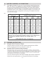
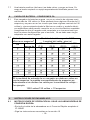
BATTERY CHARGING - AC CONNECTIONS8.
This battery charger is for use on a circuit having a nominal rating more 8.1
than 120 volts (or ″This appliance is rated more than 15 amperes and is
for use on a circuit having a nominal rating of 120 volts″) and is factory-
equipped with a specic electric cord and plug to permit connection to an
acceptable electric circuit. Make sure that the charger is connected to an
outlet having the same conguration as the plug. No adapter should be
used with this charger.
8.2
25 50 100 150
(7.6) (15.2) (30.5) (45.6)
0 2 18 18 18 16
2 3 18 18 16 14
3 4 18 18 16 14
4 5 18 18 14 12
5 6 18 16 14 12
6 8 18 16 12 10
8 10 18 14 12 10
10 12 16 14 10 8
12 14 16 12 10 8
14 16 16 12 10 8
16 18 14 12 8 8
18 20 14 12 8 6
a
If the input rating of a charger is given in watts rather than in
amperes, the corresponding ampere rating is to be determined
by dividing the wattage rating by the voltage rating ± for
example:
1250 watts/125 volts = 10 amperes
Length of cord, feet (m)
AWG size of cord
AC input rating,
amperes
a
But less
than
At least
ASSEMBLY INSTRUCTIONS9.
Using the quick Connector Clamps9.1
Plug the clamp’s connector into the connector attached to the 1562A.•
Follow charging instructions as outlined in section 10.•
Using the quick Connector Ring Terminals9.2
Ring terminals can be permanently mounted to battery. If permanently •
mounted, make sure the ring terminal cables are not obstructing or touch-
ing any live components in the vehicle. ALWAYS ensure ring terminals
are properly mounted prior to charging.
Turn the vehicle’s ignition OFF before making ring terminal connections.•
Attach the red ring terminal (+) to the positive terminal of the battery. •

• 6 •
Attach the black ring terminal (-) to the negative terminal of the battery.•
Plug the ring terminal’s connector into the connector attached to the •
1562A
Follow charging instructions as outlined in section 10.•
OPERATING INSTRUCTIONS10.
Set the 6 and 12 volt selector switch to match the voltage of the battery 10.1
being charged.
Connect charger to a battery as outlined in 10.2 Section 6 or 7.
Plug AC power cord into 120 AC volt receptacle.10.3
The YELLOW LED indicates CHARGING, the GREEN LED indicates 10.4
battery is fully CHARGED and the RED LED indicates CHECK BATTERY.
See more detailed explanation below.
When the charger is plugged into an AC outlet, but not connected to a 10.5
battery, the GREEN LED will illuminate. For proper operation, the battery
charger must be plugged into an AC outlet and connected to a battery.
When properly connected, the YELLOW LED indicator will illuminate. This 10.6
indicator will stay illuminated until the battery is fully charged. (The battery
is fully charged when battery voltage reaches approximately 14.4V.) At
that point, the YELLOW LED turns off and the GREEN LED illuminates.
When the battery is fully charged, the battery charger is in Maintain Mode 10.7
which allows the battery charger to keep the battery charged at approxi-
mately 13.2V.
Never leave the battery connected to the charger while the charger is 10.8
unplugged from the AC outlet.
The RED LED indicates an overload condition. Disconnect clamps for at 10.9
least ve seconds. Re-connect clamps, and the charger will automatically
reset to the normal charge state.
Common causes for overload: 10.10
shorting of the battery clamps •
reverse-polarity connection to a battery (battery clamps should be in a: •
+/+ and -/- connection, instead of +/- connection).
problem battery•
charging two or more batteries in parallel•
charging batteries larger than the size commonly used in a car or small •
truck.
Battery types: Most Regular, Deep Cycle and Gel Type batteries can be 10.11
maintained.

• 7 •
MAINTENANCE INSTRUCTIONS11.
Before performing maintenance, unplug and disconnect battery charger 11.1
(see sections 6.7 or 7.6).
After use, use a dry cloth to wipe all battery corrosion and other dirt or oil 11.2
from terminals, cords, and the charger case.
Servicing does not require opening unit, as there are no user-serviceable 11.3
parts.
STORAGE INSTRUCTIONS12.
Store charger unplugged, in an upright condition. Cord will still conduct 12.1
electricity until it is unplugged from outlet.
Store inside, in a dry, cool place (unless you’re using an on-board, UL 12.2
listed Marine Charger ).
Do not store clips on handle, clipped together, on or around metal, or 12.3
clipped to cables.
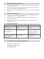
TROUBLESHOOTING13.
Problem Possible Cause Solution
Both Green and Yellow
LEDs are on.
Battery is close to fully
charge.
Just allow more time for
charging.
Green LED is on when
connected to a dis-
charged battery.
Battery is sulfated or
deeply discharged.
Keep the charger on the
battery for a few hours.
The Yellow LED will
aluminate. If not, call
customer service.
Green LED is on when
connected to a dis-
charged battery.
Wrong setting. Select the proper volt-
age setting.
ACCESSORIES AND REPLACEMENT PARTS14.
3899001235 - Alligator Clip•
94030008 Quick Disconnect•
Call: 800-621-5485

• 8 •
LIMITED WARRANTY15.
SCHUMACHER ELECTRIC CORPORATION MAKES THIS LIMITED
WARRANTY TO THE ORIGINAL PURCHASER AT RETAIL OF THIS
PRODUCT. THIS LIMITED WARRANTY IS NOT TRANSFERABLE.
Schumacher Electric Corporation warrants this battery charger for two
years from date of purchase at retail against defective material or work-
manship. If such should occur, the unit will be repaired or replaced at the
option of the manufacturer (call customer service: 800-621-5485). It is the
obligation of the purchaser to forward the unit together with proof of pur-
chase, transportation and / or mailing charges prepaid to the manufacturer
or its authorized representative. This limited warranty is void if the product
is misused, subjected to careless handling, or repaired by anyone other
than the factory or other authorized factory representative.
This is the only express limited warranty and the manufacturer neither
assumes nor authorizes anyone to assume or make any other warranty
towards the product other than this express limited warranty. The manu-
facturer makes no warranty of merchantability or tness for purpose of this
product and expressly excludes such from this limited warranty. Further,
the manufacturer specic excludes warranty of this product.
Call Customer Service at: 800-621-5485 Monday - Friday, 7 a.m. to 5 p.m.

• 9 •
MANUAL DEL DUEÑO
Modelos SE-1562A, SEM-1562A
00-99-000254/0408
Voltios: 6, 12
Amperage: 1.5
LEA TODO EL MANUAL ANTES
DE USAR ESTE PRODUCTO.
Page is loading ...
Page is loading ...
Page is loading ...
Page is loading ...
Page is loading ...
Page is loading ...
Page is loading ...
Page is loading ...
Page is loading ...
-
 1
1
-
 2
2
-
 3
3
-
 4
4
-
 5
5
-
 6
6
-
 7
7
-
 8
8
-
 9
9
-
 10
10
-
 11
11
-
 12
12
-
 13
13
-
 14
14
-
 15
15
-
 16
16
-
 17
17
-
 18
18
-
 19
19
-
 20
20


Schumacher SEM-1562A User manual
- Category
- Battery chargers
- Type
- User manual
- This manual is also suitable for
Ask a question and I''ll find the answer in the document
Finding information in a document is now easier with AI
in other languages
Related papers
-
Schumacher SE-1562A User manual
-
Schumacher SE-1562A User manual
-
-
-
-
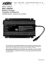 DSR INC-2405A 24V 5A Battery Charger Owner's manual
-
-
-
-
Schumacher 00-99-000886/1208 User manual

Other documents
-
Bosch MSGP3CN/02 Operating instructions
-
Schumacher Electric SE-1562A Operating instructions
-
PEAK PKC0C1 Owner's manual
-
Schumacher Electric SE-70MA Owner's manual
-
-
-
-
-
Battery Tender 100608OM User manual
-
AUTO METER BusPro-662 User manual