Electrolux CEI30EF3JSA Installation guide

Category
Cookers
Type
Installation guide
Installation Instructions
7() _ F_ec_Sta_,_di_,_!:__i/_:_ct_ic Ra__:_:_
Instructions d'installation
Electrolux
INSTALLATION AND SERVICE MUST BE PERFORMED BY A QUALIFIED INSTALLER.
IMPORTANT: SAVE FOR LOCAL ELECTRICAL iNSPECTOR'S USE.
READ AND SAVE THESE INSTRUCTIONS FOR FUTURE REFERENCE.
Clearances and Dimensions
1. Provide adequate clearances between the range and adjacent combustible surfaces.
2. Location--Check location where the range will be installed. Check for proper electrical supply, and the stability
of the floor.
3. Dimensions that are shown must be used. Given dimensions provide minimum clearance. Contact surface must
be solid and level.
FRONT
Minimum to
wall on either 1"-_
side of range
above 36" height.
_ t Minimum to
' 18" cabinets on
either side
._.........._............................................._ _ of range.
SIDE
VIEW
I_-13"_1
Maximum depth f-
for cabinets ((
above range top.
_e---25,_
30" _ O" clearance below cooking top and at rear of range.
RANGE
OVERALL
DIMENSIONS
253/4"
Center',ine
of range
q_
i
i
I .........
t
I
I outlet location are maximum.
Dashed cubed area
i sh°u_lSetWhe:t tt:heeeltc[IreC;I
I I :or flush to the wall installation.
I -11.1
2-5/8" for models equipped
with warmer drawers"
3-1/2" for models equipped
with storage drawers
*30" MINIMUM CLEARANCE BETWEEN THE TOP OF THE COOKING SURFACE AND THE BOTTOM OF AN
UNPROTECTED WOOD OR METAL CABINET; OR 24" MINIMUM WHEN BOTTOM OF WOOD OR METAL CABINET IS
PROTECTED BY NOT LESS THAN 1/4" FLAME RETARDANT MILLBOARD COVERED WITH NOT LESS THAN NO. 28
MSG SHEET STEEL, 0.015" STAINLESS STEEL, 0.024" ALUMINUM OR 0.020" COPPER. 0" CLEARANCE IS THE
MINIMUM FOR THE REAR OF THE RANGE. FOLLOW ALL DIMENSION REOUIREMENTS PROVIDED ABOVE TO
PREVENT PROPERTY DAMAGE, POTENTIAL FIRE HAZARD, AND INCORRECT COUNTERTOP AND CABINET CUTS.
TO ELIMINATE TH E RISK OF BURNS OR FIRE BY REACHING OVER HEATED SURFACE UNITS, CABINET STORAGE
SPACE LOCATED ABOVE THE SURFACE UNITS SHOULD BE AVOIDED. IF CABINET STORAGE IS TO BE
PROVIDED, THE RISK CAN BE REDUCED BY INSTALLING A RANGE HOOD THAT PROJECTS HORIZONTALLY A
MINIMUM OF 5" BEYOND THE BOTTOM OF THE CABINETS. English 1-5
pin 316454915 (0801) 1 Fran_ais - Pages 5-8
iMPORTANT SAFETY
iNSTRUCTiONS
If the informationin this manual is not followed
exactly, a fire or electrical shock may result causing property
damage, personal injury or death.
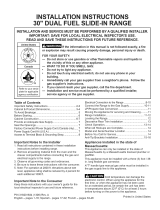
ALL RANGES
CAN TIP
INJURYTO PERSONS
COULD RESULT
o INSTALL ANTI=TIP
DEVICE PACKED WiTH
RANGE
SEE iNSTALLATiON
iNSTRUCTIONS
Important Notes to the Installer
1. Read all instructions contained in these installation
instructions before installing range.
2. Removeall packing material from the oven compartments
before connecting the gas and electrical supply to the
range.
3. Observe all governing codes and ordinances.
4. Be sure to leave these instructions with the consumer.
Important Note to the Consumer
Keep these instructions with your owner's guide for future
reference.
As when using any appliance generating heat, there are
certain safety precautions you should follow. These are
listed in the Use & Care Manual, read it carefully.
Be sure your range isinstalledand grounded properly by
a qualified installer or service technician.
Make sure the wall coverings around the range can
withstand the heat generated by the range.
To eliminate the need to reach over the surface elements,
cabinet storage space above the elements should be
avoided.
Before Starting
Tools You May Need
For leveling legs and Anti-Tip Bracket:
Adjustable wrench or channel lock pliers
5/16" Nutdriver or Flat Head Screwdriver
Electric Drill & 1/8" Diameter Drill Bit (Masonry Drill Bit if
installingin concrete)
For electrical supply connection:
1/4" & 3/8" Socket driver or Nutdriver
Additional Materials You May Need
Copper Electrical Wiring & Metal Conduit (for hard wiring)
Normal installation Steps
1. Anti-Tip Bracket Installation Instructions
Important Safety Warning
To reduce the risk of tipping of the range, the range should be
secured to the floor by properly installedanti-tip bracket and
screws packed with the range. Failure to install the anti-tip
bracket will allow the range to tip over if excessive weight is
placed on an open door or if a child climbs upon it. Serious
injury might result from spilled hot liquids or from the range
itself.
If range is ever moved to a different location, the anti-tip
brackets must also be moved and installed with the range.
instructions are provided for installation in wood or cement
fastened to either the floor or wall. When installed to the wall,
make sure that screws completely penetrate dry wall and are
secured inwood or metal. When fastening to the fiooror wall,
be sure that screws do not penetrate electrical wiring or
plumbing.
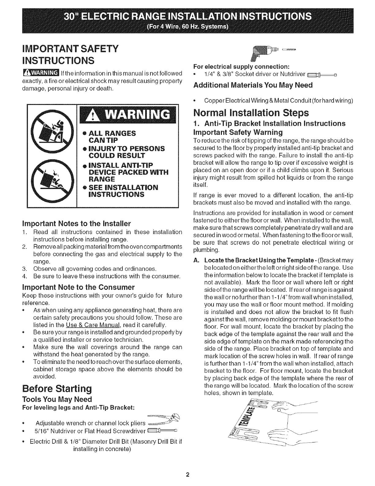
A. Locate the Bracket Using the Template- (Bracket may
be located on either the left or right side of the range. Use
the information below to locate the bracket iftemplate is
not available). Mark the floor or wall where left or right
side ofthe range will be located. Ifrear of range isagainst
the wall or no further than 1-1/4" from wall when installed,
you may use the wall or floor mount method. If molding
is installed and does not allow the bracket to fit flush
against the wall, remove molding or mount bracket to the
floor. For wall mount, locate the bracket by placing the
back edge of the template against the rear wall and the
side edge of template on the mark made referencing the
side of the range. Place bracket on top of template and
mark location of the screw holes in wall. If rear of range
isfurther than 1-1/4" from the wall when installed, attach
bracket to the floor. For floor mount, locate the bracket
by placing back edge of the template where the rear of
the range will be located. Mark the location of the screw
holes, shown in template.
g.
Drill Pilot Holes and Fasten Bracket - Drill a 1/8" pilot
hole where screws are to be located. If bracket is to be
mounted to the wall, drill pilot hole at an approximate 20 °
downward angle. If bracket isto be mounted to masonry
or ceramic floors, drill a 3/16" pilot hole 1-3/4" deep. The
screws provided may be used in wood or concrete
material. Use a 5/16" nut-driver or flat head screwdriver
to secure the bracket in place.
FASTEN BgACKET (WALL OR FLOOR MOUNTING)
--_1 I._.--I-1/4"Max.
LeveJim _.
= Wall Mount
,1
[ _ ,,? WaJJ PJate
Floor Mount _i L-Anti-Tip Bracket
2. Electrical Connection Requirements
Plug the range power cable (4 conductors) intoa 4conductor
range outlet. Outlet must be properly grounded and in
accordance with the Canadian Electrical Code (CSA Standard
(C22.1 Part 1 -- latest edition) -- and any local electrical code
requirements.
Locate outlet 6" above the floor in the wall behind the range.
This appliance may be connected by means of permanent
"Hard Wiring."
FASTEN BRACKET (FLOOR MOUNTING ONLY)
Levelim
Wall
C,
Level and Position Range - Level range by adjusting
the (4) leveling legs with a wrench. Note: A minimum
clearance of 1/8" is required between the bottom of the
range and the leveling leg to allow room for the bracket.
Use a spirit level to check your adjustments. Slide range
back into position. Visually check that rear leveling leg is
inserted intoand fully secured by the Anti-Tip Bracket by
removing lower panel or storage drawer. For models with
a warmer drawer or broiler compartment, grasp the top
rear edge of the range and carefully attempt to tilt it
forward.
Model and Serial Number Location
The serial plate is located on the right-hand surface of the
oven front frame at the storage or warmer drawer; or the
lower panel area.
When ordering parts for or making inquiresabout your range,
always be sure to include the model and serial numbers and
a lot number or letter from the serial plate on your range.
Your serial plate also tells you the Kilowatt rating (power
requirements) and Voltage ratings
Care, Cleaning and Maintenance
Refer to the Use & Care Manual for cleaning instructions.
If removing the range is necessary for cleaning or
maintenance, disconnect the electrical power supply. If the
electrical supply isinaccessible, lift the unit slightly at the front
and pull out away from the wall. Pull only as far as necessary
to disconnect the electrical supply. Finish removing the unit
forservicing and cleaning. Reinstall in reverse order making
sure to level the range and check electrical connections. See
pages 2 and 3 for proper anchoring instructions.
Before You Call for Service
Read the "Before You Call" and operating instructionsections
in your Use & Care Manual. It may save you time and
expense. The list includes common occurrences that are not
the result of defective workmanship or materials in this
appliance.
Refer to the warranty in your Use & Care Manual for our toll-
free service number and address. Please call or write ifyou
have inquiries about your range product and/or need to order
parts.
Serial plate location
Open storage or warmer drawer
or remove lower panel
(on some models)
  • Page 1 1
  • Page 2 2
  • Page 3 3
  • Page 4 4
  • Page 5 5
  • Page 6 6
  • Page 7 7
  • Page 8 8
  • Page 9 9
  • Page 10 10

Electrolux CEI30EF3JSA Installation guide

Category
Cookers
Type
Installation guide

Ask a question and I''ll find the answer in the document

Finding information in a document is now easier with AI

in other languages