User Manual AC-43 Accelerometer
11.08.2022 / V07 7 / 13
GS_AC-43_UserManual_V07
The accelerometers must be firmly mounted to a surface and levelled, as the application requires. Check to
be sure that the accelerometer is aligned to produce the desired output signals. Acceleration in the direction
indicated on the case will produce a positive output signal. The orientation definitions as shipped are:
X = East, Y = North and Z = Vertical (Up).
The accelerometer has single-bolt, 3-feet-levelling mechanism.
The surface should have a scribed north/south orientation line accurately surveyed from reliable markers.
The X-axis of the sensor has to be pointed to East or to any other main direction of the structure to monitor.
One M8 expanding nut rock anchor must be used for the sensor fixation.
4 Theory of operation
4.1 Introduction
The AC-43 sensor package is a triaxial accelerometer designed for free field and industrial applications
regarding STRONG-MOTION earthquake survey, monitoring and research. This sensor is well suited for
applications where a high sensitivity is required.
The AC-43 sensor can be optionally installed into a rugged protective housing. This optional protective
housing is in stainless steel for optimal environmental resistance. As option, the protective housing could be
executed with an IP68 grade for Free field location where the possibility exists of housing submersion.
The sensor could be installed on floor or wall with a modification of the axis organization. With the help of the
TEST LINE, the complete sensor can be very easily completely tested. Full scale can be field selected by the
user with jumpers.
4.2 Principle
The AC-43 accelerometer is based on the modern MEMS (Micro Electro-Mechanical Systems) technology,
consisting of sensing cells assembled in a way that optimizes their performances. This combined with the
state of the art proprietary circuit design yields this cost effective and reliable accelerometer.
MEMS cells include linear accelerometer sensing elements which measure the capacitance variation in
response to any movement or inclination and a factory trimmed interface chip that converts the capacitance
variations into analog or digital signal proportional to the motion.
The DC response allows the sensor to be easily repaired, tilt tested or recalibrated in the field. With the help
of the TEST LINE the AC-43 accelerometer can be completely tested assuring proper operation.
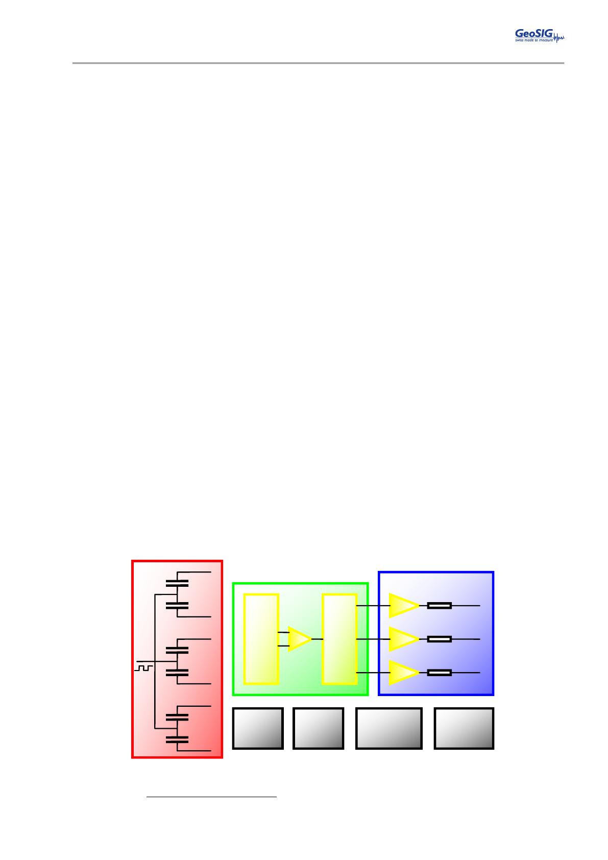
VOLTAGE AND
CURRENT
REFERENCES
CLOCK AND
PHASES
GENERATOR
Figure 5 AC-43 Sensor block diagram
The test signal will move the seismic mass. The movement of the mass generates a voltage across the
position detector, which is detected by the differential charge amplifier and induces an output signal.


