Page is loading ...

Test pressure caps device – Figure 6072 to 6075
Installation and Maintenance Instructions
Emerson reserves the right to change the contents without notice RAIIC-0051-EN-1310
1. Safety notice
Proper installation, operation and maintenance are essential to the safe and reliable operation of
valve products.
The relevant procedures recommended by Raimondi are described in this manual, and effective
methods of performing the required tasks.
It is important to note that this manual contains various ‘safety messages’ which should be
carefully read in order to minimise the risk of personal injury, or the possibility that improper
procedures will be followed which may damage the involved
Raimondi product, or render it unsafe.
It is also important to understand that these ‘safety messages’ are not exhaustive. Raimondi cannot
possibly know, evaluate, and advise any customer of all the conceivable ways in which tasks might
be performed, or the possible hazardous consequences of each way. Consequently, Raimondi has
not undertaken any such broad evaluation and, thus, who uses a procedure and/or tool, which is
not by Raimondi, or deviates from Raimondi recommendations, must be thoroughly satisfied that
neither personal safety, nor valve safety, will be jeopardised by the method and/or tools selected. If
not so satisfied, contact Raimondi if there are any questions relative to tools/methods.
Some of the products manufactured by Raimondi may be used in radioactive environments.
Consequently, before starting any operation in a radioactive environment, the proper health physics
procedures should be consulted and followed, if applicable.
The installation, operation and maintenance of valves and/or valve products may involve proximity
to fluids at extremely high pressure and/or temperature. Consequently, every precaution should be
taken to prevent injury to personnel during the performance of any procedure.
These precautions should consist of, but not limited to, ear drum protection, eye protection and
the use of protective clothing (i.e. gloves etc.) when personnel are in or around a valve work area.
Due to the various circumstances and conditions in which these operations may be performed on
Raimondi products, and because of the hazardous consequences of each way, Raimondi can not
possibly evaluate all that might injure personnel or equipment. Nevertheless, Raimondi does offer
the safety precautions listed on page 4 for customer information only.
It is the responsibility of the purchaser or user of Raimondi valves/equipment to adequately train
all personnel who will be working with the involved valves/equipment. Further, prior to working
with the involved valves/equipment, personnel who are to perform such work should become
thoroughly familiar with
the contents of this manual. Accordingly, should any additional copies of this manual be required,
they can be purchased by contacting Raimondi
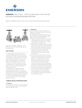
2. Introduction
This special isolator was developed to provide a simple means of isolating Test pressure cap
devices for hydrostatic test.
The product comprises a robust body in the appropriate grade of steel, having two parallel faces
inside the centre chamber.
Both of these faces, the furthest from the Test pressure cap device, is a sealing face, which is
cladded with stainless steel to prevent corrosion. The internal closure realizes a seal against this
face. During normal plant operation, the isolator acts as part of the pipe, featuring an unobstructed
flow (see Fig. 1b).
Fig. 1a
Index
1. Safety notice 1
2. Introduction 1
3. Design features 2
4. General arrangement 2
5. Parts list 3
6. Dismantling procedure 4
7. Assembly procedure 4
8. Inventory philosophy 5
9. Classification of spare parts 6
10. Factory refurbishment 7
11. Service warranty
12. Raimondi product repair by
unauthorized sources
Some of the products manufactured by Raimondi may be used in radioactive environments. Before
starting any operation in a radioactive environment, consult the proper health physics procedures
and follow them.
The installation, operation and maintenance of valves and/or valve products may involve proximity
to fluids at extremely high pressure and/or temperature. Precautions must be taken accordingly in
order to prevent injury to personnel and damage to property.
These precautions include, but are not limited to, ear drum protection, eye protection and the use
of protective clothing (gloves etc.) when personnel are in or near valve operation area. Due to the
variety of operating circumstances and conditions, Raimondi cannot possibly evaluate all situations
that might result in personal or property damage. Nevertheless, Raimondi does offer safety
precautions in page 4 for customer information only.
It is the responsibility of the purchaser or user of Raimondi valves/equipment to adequately train
all personnel who will be working with Raimondi valves/equipment. Prior to working with the
valves/equipment, personnel who are to perform such work should be familiar with the contents
of this manual. Accordingly, should any additional copies of this manual be required, these can be
purchased by contacting Raimondi.
Test closure
assembly
O-ring seal
Fig. 1b
RAIMONDI
www.valves.emerson.com

1
76228
3783717
124
17a
157a
157
105
28a
51
63
103
Test pressure caps device – Figure 6072 to 6075
Installation and Maintenance Instructions
Emerson reserves the right to change the contents without notice page 2
3. Design features
The bonnet seal in the Raimondi pressure seal test pressure cap device comprises a gasket ring in
reinforced graphite, compressed to a specific density.
The advantages of this type of seal are:
1. A normally machined sealing face is all that is required.
No lapping is involved.
2. Any minor damage to the sealing faces during maintenance only requires blending in into the
surface.
No expensive machining or lapping required.
3. The sealing ring surface does not require extremely careful handling during assembly.
4. The seal is made directly onto the body and bonnet.
There is no inlay or hard facing.
4. Internal test closure (See fig. 3)
1. This has been designed to be stored and assembled into the body as one unit.
2. Operation to realize the body/closure seal is by using a normal open ended spanner with
minimum of effort to produce the initial sealing force on the ‘O’ ring seal.
3. For safety during handling, lifting eye bolts are provided which DO NOT have to be removed at
any time during use.
5. Leakage detection (See fig. 2)
Provisions have been made in the body for leakage detection on both sides of the internal closure.
These connections are provided with a threaded plug and spiral wound stainless steel/CAF gasket.
Alternatively, by removing the plug and gasket, a pipe can be socket welded to the body without
further machining.
Fig. 2
Fig. 3
Table 1 - Partslist
Ref. No. Qty. Description Ref. No. Qty. Description
1 1 Body
2 1 Bonnet
3 1 Cover
17 1 Pressure seal gasket
17a 2 Gasket
28 * Cover stud
28a 1 Dome stud nut
37 1 Distance piece
51 1 Disk
63 2 Eyebolt
76 1 Segment ring
78 * Cover nut
78a 1 Dome nut
103 1 O-Ring
105 1 Locking plate
110 1 Name plate
124 2 Screwed plug
157 2 Shoulder screw
157a 1 Jacking screw
* Quantity depending on valve
size

4
1
3
2
Test pressure caps device – Figure 6072 to 6075
Installation and Maintenance Instructions
Emerson reserves the right to change the contents without notice page 3
6. Dismantling procedure (see Fig. 2 and Fig. 3)
6.1 To remove top cover and bonnet
1. Remove all cover nuts (78)
2. Using lifting equipment and eyebolt (63), lift the cover (3).
3. Tap down the bonnet (2), using a soft-faced hammer. This will relieve any pressure on the
segment ring (76).
4. Remove the segment ring (76) as described in section “Removal/Replacement of Segment Ring”.
5. Replace the cover (3) upside down, then using four equi-spaced cover nuts (78), “jack-up”
bonnet (2) until it comes into contact with the underside of cover (3).
6. Using lifting equipment, lift the cover (3) and bonnet (2) assembly completely, and lower to a
safe place.
7. Remove the four cover nuts (78), cover (3), distance piece (37) and pressure seal ring (17) from
the bonnet (2).
8. Inspect all cover studs (28) for wear or damage, replace with new ones as necessary
6.2 To remove internal closure
1. Unscrew hexagon-head jacking screw (157a) until locking plate (105) is approximately parallel
with the disc (51).
2. Using lifting equipment and the two eyebolts (63a), lift the closure assembly completely from the
body, taking care not to damage seat face and O-ring (103).
7. Re-assembly procedure (see Fig. 2 and Fig. 3)
7.1 To fit internal closure
1. Ensure that the body (1) seat face and disk (51) are clean.
2. Ensure that the locking plate (105) is approximately parallel with the disk (51), adjust with jacking
screw (157a) if necessary.
3. Place a new ‘O’ ring (103) into groove in disk (51) face.
4. Using lifting equipment and the two eyebolts (63), lower the closure assembly into the valve
body (1), being careful not to damage the ‘O’ ring (103) as it passes the body seating face.
5. By tightening the hexagon-head jacking screw (157a) into the locking plate (105) and against the
body, the disk (51) is loaded against the body sealing face.
Undue force is not necessary, it is sufficient to obtain contact of the sealing faces.
7.2 To re-assemble top cover and bonnet
1. Ensure that all components including the body/bonnet sealing areas and segment ring groove
are thoroughly cleaned.
2. Using lifting equipment, lower the bonnet (2) into the body (1).
3. Fit a new pressure seal ring (17) onto the bonnet (2) inside the body
4. Fit the distance piece (37), with tapped holes uppermost, using this to tap the pressure seal ring
(17) into position.
5. Refit the segment ring (76) as described in the section “Removal/replacement of segment ring”.
6. Fit the cover (3) and cover nuts (78), tighten the nuts evenly; this will jack up the bonnet (2) and
load the pressure seal ring (17) against the body (1) and bonnet (2).
Note
Further tightening or “following up” of the cover nuts must be carried out at regular intervals when
raising pressure in the valve pipeline, until there is no further movement.
6.3 Removal/replacement of segment ring (76)
1. Insert the knock-out pin into the knock-out hole located in the side of the body (1). Remove each
segment in the order shown (1, 2, 3 & 4).
2. Clean the segment ring (76) and the groove in the body (1) thoroughly, ensuring that any burrs
or debris are removed.
3. Refit the segment ring (76) in reverse order(i.e. 4, 3, 2 & 1), ensuring that each segment is fully
home in the groove and that they are aligned with the knock-out holes to facilitate their removal
in future.
Caution
Ensure that the valve pipeline is
depressurized and drained before
dismantling the valve.
Valve body
Segments
Knock-out
holes
Segment
knock-out pin
for removing
segments

8. Service parts inventory philosophy
The basic objective in formulating a service parts inventory policy is to provide prompt valve
service capability, thus preventing maintenance outage time extension. To accomplish this, it is
necessary to have immediate availability of the proper inventory of service parts for optimum valves
quantities. This can be achieved at minimum cost by defining the inventory on a frequency of need
basis.
To assist towards this objective, the field service and repair organization of Raimondi recommends
following these guidelines to establish meaningful inventory levels:
1. Identify the total number of valves in service by size, type number, pressure/temperature class,
tag number.
2. Identify the frequency of replacement tendency of specific parts:
Class I Parts most frequently replaced.
Class II Parts less frequently replaced, but critical in the event of an emergency requirement.
Class III Parts seldom replaced.
Class IV Hardware (e.g. nuts, bolts, pins, cap components etc.).
Class V Parts practically never requiring replacement.
Test pressure caps device – Figure 6072 to 6075
Installation and Maintenance Instructions
Emerson reserves the right to change the contents without notice page 4
3. “Need probability coverage’ is defined as the probable percent (%) of total, uninterrupted
operational time which can be expected by stocking predetermined valve component
classifications.
Determine “need probability coverage” which is compatible with a specific company’s
operational objectives and service parts inventory investment philosophy. Then relate “need
probability coverage” to parts classifications, which will satisfy that need.
Guidelines are as follows:
Parts classification Need Probability Coverage
Class I 70%
Class I and II 85%
Class I, II and III 95%
Class I, II, III and IV 99%
4. Consult the recommended spare parts list by valve type to determine the quantity of valve parts
to be covered by the inventory plan.
5. Select parts and specify quantities.
9. Identification and ordering essentials
When ordering service parts, please provide the following information to ensure receiving the
correct replacement parts:
Identify valve by Specify parts required by
1. Full Product No. 1. Part Name
2. Size 2. Part Number (if known)
3. Type 3. Quantity
4. Pressure/Temperature Class
5. Tag Number
Classification of spare parts
Classification Item No. Description
CLASS I 17 Pressure seal
Parts most frequently replaced 17a Gasket
103 O-ring
CLASS II 124 Screwed plug
Parts less frequently replaced but
critical in case of an emergency
CLASS III 37 Distance Piece
Parts seldom replaced 51 Disk
76 Segment ring
105 Locking plate
157 Shoulder screw
157a Jacking screw
CLASS IV 28 Cover stud
Hardware (e.g. nuts, studs, pins, etc.) 28a Dome nut stud
63 Eyebolt
78 Cover nut
78a Dome nut
CLASS V 1 Body
Parts practically never requiring 2 Bonnet
replacement 3 Cover

Emerson reserves the right to change the contents without notice page 5
Test pressure caps device – Figure 6072 to 6075
Installation and Maintenance Instructions
10. Factory refurbishing
Many customers find it desirable to return their valves to Raimondi for restoration or modernization.
Products returned to the Raimondi valve repair centre are restored to original specifications and
returned with a new valve warranty.
11. Service warranty
Factory repaired valves carry a warranty that covers workmanship and new parts installed during
the repair, for a period of one year from date of repair completion.
11. Raimondi product repair by unauthorized sources
Raimondi has not authorized any outside repair companies, contractors, or individuals to perform
warranty repair service on new products, or field/factory repaired products of its manufacture.
Therefore, customers contracting such repair services from unauthorized sources, do so at their
own risk.
Likewise, if any Raimondi product fails to perform within the scope of its design, Raimondi must be
notified and given the opportunity to inspect and correct the problem. Raimondi will not accept any
back charges for unauthorized repair sources performing corrective repairs on its products.
/