
FLECK 9100TS UPFLOW
SERVICE MANUAL
waterpurification.pentair.com

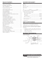
TABLE OF CONTENTS
JOB SPECIFICATION SHEET .................................................... 2
HOW TO USE THIS MANUAL .................................................... 2
EQUIPMENT CONFIGURATION ................................................ 2
SAFETY INFORMATION ............................................................ 3
INSTALLATION INSTRUCTIONS ............................................... 3
CONTROLLER FEATURES ........................................................ 6
INITIAL STARTUP INSTRUCTIONS .......................................... 7
USER PROGRAMMING ............................................................. 8
PROGRAMMING MODE ............................................................ 11
AUTOMATIC CLEANING CYCLE ............................................... 15
DISINFECTION OF WATER CONDITIONING SYSTEMS ............ 15
WIRING DIAGRAMS .................................................................. 16
POWERHEAD ASSEMBLY......................................................... 17
9100 CONTROL VALVE ASSEMBLY .......................................... 18
9100 SECOND TANK ASSEMBLY ............................................. 19
TURBINE METER ASSEMBLY - P/N 60626 ............................. 20
PADDLE METER ASSEMBLY -P/N 60086-50 ........................... 20
1" METER ASSEMBLY - P/N 60622 .......................................... 21
BYPASS VALVE ASSEMBLY (METAL) ........................................ 22
BYPASS VALVE ASSEMBLY (PLASTIC) ..................................... 22
SAFETY BRINE VALVE .............................................................. 23
PROBE KIT ............................................................................... 24
TROUBLESHOOTING ................................................................ 25
9000/9100 METER FLOW DATA ................................................ 26
9000/9100 INJECTOR FLOW DATA (
1600 SERIES INJECTORS) ....................................................... 27
9100 CONTROL DIMENSIONS.................................................. 28
WATER CONDITIONER FLOW DIAGRAMS ............................... 29
SERVICE ASSEMBLIES ............................................................ 31
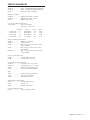
JOB SPECIFICATION SHEET
Job No: _____________________________________________
Model No: ___________________________________________
Water Test: __________________________________________
Capacity Per Unit: _____________________________________
Mineral Tank
Size: ____________ Diameter: ___________Height: _________
Brine Tank Size and Salt Setting per Regeneration: _________
9100TS Control Valve Specifications:
1. Regeneration Program Setting:
a. Brine and Slow Rinse: ______________________ Minutes
b. Backwash: _______________________________ Minutes
c. Rapid Rinse: _____________________________ Minutes
d. Brine Tank Refill: _________________________ Minutes
2. Drain Line Flow Control: _________________________ gpm
3. Brine Refill Rate: _______________________________ gpm
4. Injector Size: ______________________________________
HOW TO USE THIS MANUAL
This installation manual is designed to guide the installer
through the process of installing and starting water
conditioning systems featuring the 9100TS controller.
This manual is a reference and will not include every system
installation situation. The person installing this equipment
should have:
• Training in the 9100TS control and the 9000/9100 valve.
• Knowledge of water conditioning and how to determine
proper control settings.
• Adequate plumbing skills.
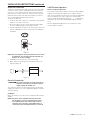
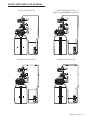
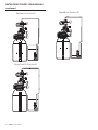
EQUIPMENT CONFIGURATION
9100TS Configuration
Figure 1
CALIFORNIA PROPOSITION 65 WARNING
WARNING:
This product contains chemicals known to the
State of California to cause cancer or birth
defects or other reproductive harm.

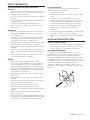
SAFETY INFORMATION
General Warnings And Safety Information
Electrical
• There are no user-serviceable parts in the AC adapter,
motor, or controller. In the event of a failure, these items
should be completely replaced.
• All electrical connections must be completed according to
local codes.
• Use only the power transformer supplied with this water
conditioning system.
• The power outlet must be grounded and always on.
• To disconnect power, unplug the AC adapter from its
power source.
Mechanical
• Do not use petroleum based lubricants such as Vaseline,
oils, or hydrocarbon based lubricants. Use only 100%
silicone lubricants.
• All plastic connections should be hand tightened. PTFE
tape may be used on connections that do not use an
O-ring seal. Do not use pliers or pipe wrenches.
• All plumbing must be completed according to local codes.
• Use only lead-free solder and flux, as required by
federal and state codes, when installing soldered copper
plumbing.
• The drain line must be a minimum of 1/2-inch diameter.
Use 3/4-inch pipe if the pipe length is greater than 20 feet
(6 m).
• Do not support the weight of the system on the control
valve fittings, plumbing, or the bypass.
General
• Observe all warnings that appear in this manual.
• This system is not intended to be used for treating water
that is microbiologically unsafe or of unknown quality
without adequate disinfection before or after the system.
• Keep the unit in the upright position. Do not turn on side,
upside down, or drop. Turning the tank upside down will
cause media to enter the valve.
• Operating water temperature is between 35°F (1°F) and
100°F (38°C).
• Operating water pressure range : 20 to 125 psi (1.38 to
8.27 bar).
• Use only salts designed for water softening. Acceptable
salt type is sodium chloride pellet salt.
• Follow state and local codes for water testing.
• When filling media tank, do not open water valve
completely. Fill tank slowly to prevent media from exiting
the tank.
• Always make modifications to house plumbing first.
Connect to valve last.
• Plastic parts and O-rings may be damaged by heat and
solvents. When constructing plumbing connections allow
heated parts to cool and protect parts from solvents.
Location Selection
Location of a water treatment system is important. The
following conditions are required:
• Level platform or floor.
• Ambient temperatures over 35°F (1°C) and below 120°F
(49°C).
• Constant electrical supply to operate the controller.
• Total minimum pipe run to water heater of ten feet (three
meters) to prevent backup of hot water into system.
• Local drain or tub for discharge as close as possible.
• Water line connections with shutoff or bypass valves.
• Must meet any local and state codes for site of
installation.
• Valve is designed for minor plumbing misalignments. Do
not support weight of system on the plumbing.
• Room to access equipment for maintenance and adding
salt.
INSTALLATION INSTRUCTIONS
Things You Need to Know
• When the controller is first plugged in, it may display a
flashing hourglass and the message Err 3, this means
that the controller is rotating to the home position.
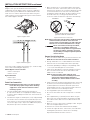
Grounding the Plumbing
It is important that the plumbing system be electrically
grounded. When a water softener is installed, a non-metallic
bypass valve may interrupt the grounding. To maintain
continuity, a grounding strap can be purchased at a hardware
store (Figure 2). When it is installed the strap will connect the
plumbing into the softener to the plumbing out of the softener.
If you have other water treating equipment such as a
chlorinator, sediment filter, neutralizer, iron filter, or taste
and odor filter they should be installed upstream of the water
softener.
Figure 2
FLECK 9100TS Upflow • 3

Bypass Valve
A bypass valve system should be installed on all water
conditioning systems. Bypass valves isolate the conditioner
from the water system and allow unconditioned water to be
used. Service or routine maintenance procedures may also
require that the system is bypassed. Figures 3 and 4 show the
two common bypass methods.
Figure 3 Bypass Valve
1
2
3
B
Figure 4 Manual Bypass
If this unit includes a bypass valve (Figure 3), it can be used by
itself or with a manual bypass (Figure 4).
Manual Bypass In Service Position
• Valves 1 and 3 open
• Valve 2 closed
Bypassed Position
• Valve 2 open
• Valves 1 and 3 closed
Drain Line Connection
NOTE: Standard commercial practices are expressed here.
Local codes may require changes to the following
suggestions. Check with local authorities before
installing a system.
1. The unit should be above and not more than 20 feet
(6.1 m) from the drain. Use an appropriate adapter fitting
to connect plastic tubing to the drain line connection of the
control valve.
2. The drain line may be elevated up to 6 feet (1.8 m) providing
the run does not exceed 15 feet (4.6 m) and water pressure
at the softener is not less than 40 psi (2.76 bar). Elevation
can increase by 2 feet (61 cm) for each additional 10 psi (.69
bar) of water pressure at the drain connector.
INSTALLATION INSTRUCTIONS continued
3. Where the drain line is elevated but empties into a drain
below the level of the control valve, form a 7-inch (18-cm)
loop at the far end of the line so that the bottom of the loop
is level with the drain line connection. This will provide
an adequate siphon trap. Where the drain empties into an
overhead sewer line, a sink-type trap must be used.
Secure the end of the drain line to prevent it from moving.
1" AIR GAP
INCORRECT
Construct air gap as shown or purchase air
gap device as used with clothes washers.
CORRECT
Figure 5 Drain Line Connection
NOTE: Waste connections or drain outlets should be designed
and constructed to provide for connection to the
sanitary waste system through an air gap of two pipe
diameters or one inch (22 mm) whichever is larger.
WARNING:
Never insert drain line directly into a drain,
sewer line, or trap (Figure 5 Drain Line
Connection). Always allow an air gap between
the drain line and the wastewater to prevent
the possibility of sewage being back-siphoned
into the softener.
General Installation Notes
1. Place the softener tanks where you want to install the unit.
NOTE: Be sure the tanks are level and on a firm base.
2. During cold weather it is recommended that the installer
warm the valve to room temperature before operating.
3. Perform all plumbing according to local plumbing codes.
— Use a 1/2" minimum pipe size for the drain.
4. Lubricate the distributor O-ring seal and tank O-ring seal.
Place the main control valve on one tank and the tank
adapter on the second tank.
NOTE: If required, solder copper tubing for tank
interconnection before assembling on the main
control valve and tank adapter. Maintain a
minimum of 1" distance between tanks on final
assembly.
5. Solder joints near the drain must be done before connecting
the Drain Line Flow Control fitting (DLFC).Leave at least
6" (152 mm) between the DLFC and solder joints when
soldering pipes that are connected on the DLFC. Failure to
do this could cause interior damage to DLFC.
6. Use only plumber tape on the drain fitting.
7. Be sure the floor under the salt storage tank is clean and
level.
8. Place approximately 1" (25 mm) of water above the grid
plate of the salt storage tank before filling with salt. Add
salt to brine tank so that salt level is above the brine well
air check.
9. Make all electrical connections according to codes. Plug the
valve into an approved power source.
10. Tank one has control valve and tank two has adapter.
11. Look on the right side of the control valve, it has indicators
showing which position the control valve is in during
Regeneration and which tank is In Service.
4 •
FLECK 9100TS Upflow

INSTALLATION INSTRUCTIONS continued
Brine Line Connection
The brine line from the brine tube connects to the valve. Make
certain the connections are hand tightened. Be sure that the
salt line is secure and free from air leaks. Even a small leak
may cause the salt line to drain out, and the softener will not
draw salt from the tank. This may also introduce air into the
valve causing problems with valve operation.
To install the brine line:
1. Inside the salt tank, remove the cap from the large cylinder
to gain access to the connection.
2. Be sure the brass insert is in the end of the brine tubing.
Insert the tubing through the opening in the tank.
3. Push the tubing into the plastic nut. Slowly unscrew the nut
until the tubing moves into the connection. The tubing will
hit bottom.
Figure 6
NOTE: Once the tubing has been pushed into the nut it cannot
be pulled out. The nut will need to be removed. See
Figure 6 for correct assembly.
4. Hand tighten the nut until the connection is tight.
5. Make compression fitting connection between brine line
and valve (Figure 7).
Figure 7
Electrical Connection
WARNING:
This valve and control are for dry location use
only unless used with a Listed Class 2 power
supply suitable for outdoor use.
The controller operates on 24-volt alternating current power
supply. This requires use of the supplied AC adapter included
with your system.
AC Adapter
Make sure power source matches the rating printed on the AC
adapter.
NOTE: The power source should be constant. Be certain
the AC adapter is not on a switched outlet. Power
interruptions longer than 8 hours may cause the
controller to lose the time setting. When power is
restored, the time setting must then be re-entered.
9100TS Control Operation
Power Loss Memory Retention
The 9100TS control features battery-free Time of Day and Day
of Week retention during temporary loss of power. A super
capacitor is designed to keep time for 8 to 24 hours depending
on the installation. If the super capacitor is exhausted the
9100TS control will display four dashes (- - : - - ) immediately
upon power up. The Time of Day and Day of Week must be
reset.
All other programmed parameters are stored in the static
memory and are retained.
FLECK 9100TS Upflow • 5

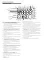
CONTROLLER FEATURES
Display Icons & Cursors
Time/Day
Regeneration Time
Salt Amount
Capacity
SU MO TU WE TH FR SA DAYS
Hardness
g/L
PM
MIN
KGx2
x100P
HC
Lbs/ft
3
2
1
3
4
5
6
17
18
19
20
21
22
23
24
25
26
11
12
15
13
14
16
9
10
8
7
NOTE: In normal operation and during programming, only a
few of the icons are actually displayed.
1. This cursor is displayed when the days between
regeneration are being programmed (used with .5 to 30 day
regeneration programming).
2. One of these cursors is displayed to indicate which day will
be programmed into the controller.
3. "PM" indicates that the time displayed is between 12:00
noon and 12:00 midnight (there is no AM indicator). PM
indicator is not used if clock mode is set to 24-hour.
4. When "MIN" is displayed, the value entered is in minute
increments.
5. When g/L is displayed, the value for regenerant amount
entered is in grams/Liter of resin.
6. When "Kg" is displayed, the value entered is in kilograms or
kilograins.
7. Four digits used to display the time or program value. Also
used for error codes.
8. Colon used as part of the time display.
9. Locked/unlocked indicator. In Level I Programming this
is displayed when the current parameter is locked-out.
It is also used in Level II Programming to indicate if
the displayed parameter is locked (icon flashes) when
controller is in Level I.
10. When "x2" is displayed, a second regeneration has been
called for.
11. The recycle sign is displayed (flashing) when a regeneration
at the next time of regeneration has been called for. Also
displayed (continuous) when in regeneration.
12. The display cursor is next to "SALT AMOUNT" when
programming the amount of regenerant.
13. The display cursor is next to "REGENERATION TIME" when
programming the time of regeneration and the days of
regeneration.
14. The display cursor is next to "TIME/DAY" when
programming the current time and day.
15. The hourglass is displayed when the motor is running. The
piston should be moving.
16. These cursors appear next to the item that is currently
displayed.
17. X100 multiplier for large values.
18. When Lbs/ft
3
is displayed the value for regenerant amount
entered is in pounds/cubic foot of resin.
19. Faucet is displayed when the current flow rate is displayed.
Control may show the faucet and "0", indicating no flow.
20. Maintenance interval display turns on if the months in
service exceed the value programmed in P11.
21. Displays the tank in service during normal operating mode.
Used with #22, #23 and #24 in programming mode or
regeneration.
22. History Values (H). The number displayed by #21 identifies
which history value is currently displayed.
23. Parameter (P). Displayed only in Level II Programming.
The number displayed by #21 identifies which parameter is
currently displayed.
24. Cycle (C). The number displayed by #21 is the current cycle
in the regeneration sequence.
25. Hardness setting.
26. Capacity display—shows estimated system capacity.
6 •
FLECK 9100TS Upflow

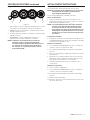
Keypad - Buttons
1 2 3 4
Figure 8
1. SET. Used to accept a setting that normally becomes stored
in memory. Also used together with the arrow buttons.
2. DOWN arrow. Generally used to scroll down or decrement
through a group of choices.
3. UP arrow. Generally used to scroll up or increment through
a group of choices.
4. REGENERATE. Used to command the controller to
regenerate. Also used to change the lock mode.
NOTE: If a button is not pushed for thirty seconds, the
controller returns to normal operation mode.
Pushing the Regenerate button immediately returns
the controller to normal operation except when
the controller is in regeneration mode or Level II
Programming mode.
CONTROLLER FEATURES continued INITIAL STARTUP INSTRUCTIONS
After you have performed the installation steps, the conditioner
will need to be placed into operation for the first time.
NOTE: The controller will be shipped in the service (treated
water) position. Do not move the piston before
performing the following steps.
The incoming supply water should be turned off.
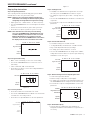
Power-up The Control
1. Plug the transformer into a non-switched outlet. The
display will show 9100. If this is the first time the control is
powered up the display will show "_.__".
NOTE: err3 will be displayed if the control does not detect
the valve at the home position and that the motor
is turned on. As soon as it detects the valve at the
home position, the motor will be turned off and error
will disappear. The piston will move to service if not
already in service. These movements may take up to
five minutes.
Program the Controller
2. Program the Controller for initial operation using the User
Programming Guide (See Quick Start on page 8 or Step-by-
Step Instructions on pages 9-10).
Remove Air From Tank 1
3. Press and hold the REGEN button for three seconds. The
controller will enter regeneration mode.
4. Press both SET and UP buttons to advance to backwash
(Cycle 2).
5. Open the incoming water supply valve slowly to the quarter
open position.
6. Allow water to run down the drain until air exits the tank.
When water flows steady from the drain, open inlet valve
fully. Allow to run until water is clear in drain.
7. Hold SET and UP buttons for three seconds to cancel
regeneration.
Remove Air From Tank 2
8. Close inlet water supply valve.
9. Press and hold the REGEN button for three seconds. The
controller will enter regeneration mode.
10. Press both SET and UP buttons to advance to backwash
(Cycle 2).
11. Repeat steps 5 and 6 above.
12. Allow the controller to finish regeneration on its own. This
will fill the brine tank.
FLECK 9100TS Upflow • 7

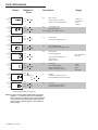
USER PROGRAMMING
Level I Programming - 9100TS
NOTE: The regen icon may begin flashing after the control
displays err3 or after the time is reset following a
power outage. This indicates that a regeneration will
occur at the next scheduled regeneration based on
metered water usage during the error condition or
power outage.
Time/Day
Regeneration Time
Salt Amount
SU MO TU WE TH FR SA DAYS
Capacity
Salt Amount
SU MO TU WE TH FR SA DAYS
Capacity
Salt Amount
SU MO TU WE TH FR SA DAYS
Capacity
SU MO TU WE TH FR SA DAYS
Capacity
Salt Amount
SU MO TU WE TH FR SA DAYS
Capacity
Salt Amount
SU MO TU WE TH FR SA DAYS
Capacity
Salt Amount
SU MO TU WE TH FR SA DAYS
Capacity
KG
Screen Buttons to Description Range
Press
or
press
then
or
press
press
then
or
press
press
then
or
press
press
then
or
press
press
then
or
press
press
then
press
PM
Lbs/ft
3
Salt Amount
SU MO TU WE TH FR SA DAYS
Capacity
or
press
press
then
or
press
press
then
to override
Control programming is complete
Hardness
Hardness
Hardness
Hardness
Hardness
Hardness
Hardness
Hardness
Time/Day
Regeneration Time
Time/Day
Regeneration Time
Time/Day
Regeneration Time
Time/Day
Regeneration Time
Time/Day
Regeneration Time
Salt Amount
Time/Day
Regeneration Time
Time/Day
Regeneration Time
P0 Resin Volume
Select correct resin volume.
Default is 1 cubic foot/30 liters.
Cubic Feet:
0.75 to 2.00
Liters:
20 to 60
P1 Time of Day (12 hr)
Set to me of day.
Note: Seng includes PM indicator.
P2 Day of Week
Set to actual day of the week.
P3 Time of Regeneraon
Set to desired me of regeneraon.
P4 Days Override
Leave at 0 to disable
or
Set to desired days between
regeneraon.
Default is 0 days.
Days: 0 (Disable)
0.5 to 30
P6 Salt Dosage
Set to desired dosage
lbs per cubic feet of resin
Default is 9 lbs/ / 110 gm/l.
3
Lbs/ :
3 to 15
gm/l:
50 to 200
3
P7 Capacity
Capacity calculated by control
Use to OVERRIDE calculated capacity.
P8 Hardness
Set to actual water hardness
in grains per gallon / ppm.
8 • FLECK 9100TS Upflow

USER PROGRAMMING continued
Step-by-Step Instructions
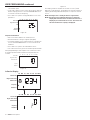
Step 1: Program System Size
This step may have been performed by your system’s OEM
manufacturer. In this case, proceed to step 2.
NOTE: Capacity is the result of the amount of media in the
tank and the salt setting. The default capacity will be
changed by selecting a different regenerant setting.
• Input system size – media volume – in cubic feet (liters).
• Use UP and DOWN buttons to scroll through resin volume
choices.
• Choose the nearest volume to your actual system size.
• Press SET to accept the system size you’ve selected.
NOTE: If the controller was incorrectly set to the wrong
size, press the DOWN button and SET button for five
seconds to display resin volume in "HO". Press and
hold the SET button for five seconds to reset the
controller. Use the UP or DOWN buttons to increment
the display to the correct resin volume. Press SET.
Time & Day
Regen
Time & Day
Salt
SU MO TU WE TH FR SA DAYS
Capacity
Hardness
Figure 9
Step 2: Program Time of Day
• While “12:00” is blinking, set the correct time of day.
• Use the UP and DOWN buttons to scroll to the correct
time of day.
• “PM” is indicated, “AM” is not indicated.
• Press SET to accept the correct time of day and advance
to the next parameter.
Time & Da
y
SU MO TU WE TH FR SA DAYS
Capacity
Hardness
Figure 10
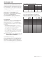
Step 3: Set Day of Week
• Press SET to make the arrow under “SU” flash.
• Use the UP and DOWN buttons to advance the arrow until
it is under the correct day of week.
• Press SET to accept and advance to the next parameter.
Time & Day
Regen
Time & Day
Salt
SU MO TU WE TH
FR
SA DAYS
Capacity
Hardness
Figure 11
Step 4: Set Regen Time
• 2:00 (AM) is the default time of regeneration. To accept
this time, press the DOWN button to move to step 5.
• To change the regen time, press SET – causing “2:00” to
flash.
• Use the UP and DOWN buttons to advance to the desired
regen time.
• Press SET to accept the time and advance to the next
parameter.
Time & Day
Regen
Time & Day
Salt
SU MO TU WE TH FR SA DAYS
Capacity
Hardness
Figure 12
Step 5: Set Calendar Override
• Set number of days for calendar override.
• “0” days (disabled) is the default for calendar override.
• Days can be adjusted from ½ (.5) to 30 days.
• To change, press SET to make the “0” flash.
• Use the UP and DOWN buttons to change to the number
of days desired. Press SET to accept the regen frequency,
and advance to the next cycle.
Time & Day
Regen
Time & Day
Salt
SU MO TU WE TH FR SA DAYS
Capacity
Hardness
Figure 13
Step 6: Amount of Regenerant used per Regeneration
• Set desired regenerant amount.
• Default setting is 9 lbs/cubic feet (120 gm/l).
• To change salt setting, press the SET button and use the
UP and DOWN buttons to change to the desired setting.
• Press SET to accept the setting and advance to the next
parameter.
Salt Amount
SU MO TU WE TH FR SA DAYS
Capacity
Lbs/ft
3
Hardness
Time/Day
Regeneration Time
Figure 14
Step 7: Estimated Capacity
• System capacity is displayed in total kilograins or
kilograms of hardness removed before a regeneration is
necessary.
FLECK 9100TS Upflow • 9

• Value is derived from the system’s resin volume input and
salt amount input.
• To override capacity on the control, press SET to make the
default capacity flash. Use the UP and DOWN buttons to
increment to the desired capacity.
• Press SET to accept the setting and advance to the next
parameter.
KG
Time & Day
Regen
Time & Day
Salt
SU MO TU WE TH FR SA DAYS
Capacity
Hardness
Figure 15
Step 8: Enter Hardness
• Enter inlet water hardness at installation site.
• Default hardness setting is 10 grains (170 ppm).
• To change hardness, press SET to make the setting flash.
Use the UP and DOWN buttons to scroll to the desired
hardness.
• Press SET to accept the entered hardness value.
• The control will return you to the normal operation mode.
Initial programming is now complete. The control will return
to normal operation mode if a button is not pushed for 30
seconds.
Time & Day
Regen
Time & Day
Backwash Time
SU MO TU WE TH FR SA DAYS
Capacity
Hardness
Figure 16
In Service Display
Time & Day
Regen Time & Day
Salt Amount
SU MO TU WE TH FR SA DAYS
Capacity
Time & Day
Regen Time & Day
Salt Amount
SU MO TU WE TH FR SA DAYS
Capacity
Hardness
Hardness
Figure 17
The display shows the number of the tank in service (small
digit next to CPH position). The display also alternates between
Capacity Remaining and Flow Rate (faucet icon) for the tank in
service.
NOTE: The Regen icon is steady on when in regeneration.
NOTE: The faucet icon is displayed when there is flow. The
display will show the faucet icon when the flow rate is
displayed, even if the flow rate is zero. The faucet icon
will turn off when the capacity is displayed.
USER PROGRAMMING continued
10 • FLECK 9100TS Upflow

Programming Overview
The 9100TS control includes multiple program levels that
allow water treatment professionals to customize the system
for many water conditions. Additionally, historical data can be
viewed allowing quick and easy troubleshooting. In most cases
Level I Programming is all that is required to set up the water
conditioning system for proper operation. A brief description of
each program level is listed below.
Level I - Used to program control for normal applications.
Level II (P-Values) - Allows the installer to customize
programming for non-standard applications including
parameters that are also programmable in Level I.
Level III (C-Values) - Allows the installer to adjust length of
select cycles for non-standard applications.
Level IV History (H-Values) - Allows access to historical
information for troubleshooting the system.
NOTE: If a button is not pushed for thirty seconds, the control
returns to normal operation mode.
Level I Programming
The 9100TS control can be quickly programmed by following
the sequential procedure in the section "Placing Water
Conditioning System Into Operation". Level I Program
parameters are those that can be accessed by pressing the
UP or DOWN buttons. Step-by-step instructions are shown on
previous page.
• Resin Volume Setting: Set to match the volume (cubic
feet) of resin in the mineral tank.
• Time of Day: Includes PM indicator. Can be set to display
as a 24-hour clock. See Level II programming.
• Day of Week: Set to actual day of the week.
• Time of Regeneration: Fully adjustable. Default is 2:00 AM.
• Days Override: Range 0.5 to 30 days. Leave at 0 to disable.
• Salt Dosage: Set at pounds of salt per cubic foot of resin
in the conditioner tank.
NOTE: When the control is set up for a twelve-hour clock a PM
indicator will illuminate when the displayed time is in
the PM hours. There is no AM indicator.
Programming the Lockout Feature
All Level I parameters can be locked out when the control is in
Level II Programming. Simply press the REGEN button during
Level II Programming and a lock icon will appear indicating
that the specific setting has been locked out. When locked
out, the setting cannot be adjusted in Level I Programming. To
disable the Lock Out feature, press the REGEN button when in
Level II. The lock icon will not be displayed.
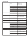
PROGRAMMING MODE
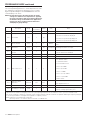
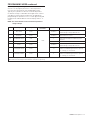
Injector and Brine Line Flow Control Sizing
Tank Diameter
(inches)
Resin Volume
Injector BLFC
US Metric
8 0.75 20 #000 0.125
9 1.00 30 #000 0.125
9 1.25 35 #000 0.125
10 1.50 45 #000 0.125
12 2.00 60 #00 0.5
Salt Setting
The default P6 salt setting is set at 9 lbs/cu ft (110 g/l). Under
normal circumstances this setting will provide the correct
system capacity. The exchange capacity setting P7 will
automatically change when the salt setting P6 is changed.
Salt Setting
lbs/cu ft
Exchange
Capacity
grains/cu ft
Salt Setting
grams/liter
Exchange
Capacity
grams/liter
3 14631 50 34.4
4 17799 60 38.9
5 20682 70 43.2
6 23279 80 47.3
7 25592 90 51.1
8 27619 100* 54.6
9* 29361 110 57.9
10 30818 120 60.9
11 31990 130 63.7
12 32877 140 66.2
13 33478 150 68.5
14 33795 170 72.2
15 33826 200 76.0
*Default Setting.
FLECK 9100TS Upflow • 11

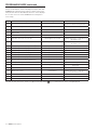
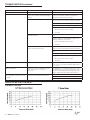
Level II Programming - P Values
Level II Programming parameters can be adjusted to fine-tune
the conditioner's operation. The parameters are accessible
by pressing and holding the UP and DOWN buttons until the
control displays a "P" value.
NOTE: The control must be in the home position to change
settings. See Table for Level II parameters. Typically
the Level II parameters will not need to be adjusted as
the default settings accommodate most applications.
Contact your water treatment professional before
attempting any programming.
Description Range
Minimum
Increments
Default Units Notes
P9 Units of Measure 0-1 1 (2) 0 = US 1 = Metric
P10 Clock Mode 0-3 1 (2)
0 = 12 hour clock: flow rate displayed
1 = 24 hour clock: flow rate displayed
2 = 12 hour clock; Time of Day displayed
3 = 24 hour clock; Time of Day displayed
P11 Service Interval 0-99 1 0 Months
0 = Dissabled. Number of days per month is fixed
at 30.
P12*
Resin Tank Sensor
Placement
60-01 1 20 % of Capacity
Expressed as a percentage of resin bed capacity
remaining after lowest set of pins.
P13
Disable Resin Tank
Sensors
0-1 1 0
0 = Resin Tank Sensors Enabled
1 = Resin Tank Sensors Disabled
P14 Refill Rate 1-700 1 (1) gpm x 100 Used with salt amount to calculate refill time.
P15 Draw Rate 1-700 1 (1) gpm x 100 Used with salt amount to calculate draw time.
P16 Flow sensor select 1-4 1 4
1 = 1" Autotrol turbine
2 = 2" Autotrol turbine
3 = User defined K-factor
4 = Fleck 3/4" Paddle
5 = Fleck 3/4" Turbine
6 = Fleck 1" Paddle
7 = Fleck 1"/1-1/2" Turbine
8 = Fleck 1-1/2" Paddle
9 = Meter Factor
P17
K-factor or Pulse
equivalent
0.01-99.99 0.01 0.01
K-factor P16 = 3;
Pulse Equivalent P16 = 9
P18 Tank in Service 1-2 1 1 Select the Tank in Service.
P19 Cleaning Cycle Interval 0-100 1 6
Number of standard regeneration cycles
between cleaning regeneration cycles.
*The control will automatically adjust the Hardness Setting P8 when the sensors in the resin tank detect a hardness front passing. This automatic
adjustment to the hardness setting may result in the system passing hard water near the end of the service cycle if the resin tank sensor
placement setting P12 is wrong. The sensor placement setting P12 must be reduced to eliminate the problem. Reducing the Capacity Setting P7
or increasing the Hardness setting P8 will only produce a temporary solution.
NOTE: (1) Default selected with initial setting value.
(2) Facotry Default is "0" for North America units and "1" for World units.
PROGRAMMING MODE continued
12 • FLECK 9100TS Upflow

PROGRAMMING MODE continued
Level III Cycle Programming - C Values
Several Level III program parameters can be adjusted to
fine-tune valve operation for non-standard applications.
Typically these parameters will not need to be adjusted as
the default settings accommodate most applications. Contact
your Water Treatment Professional before attempting any
programming. The parameters are accessible by pressing and
holding the UP and SET buttons until the display shows a “C”
value.
NOTE: The control must be in the treated water position to
change settings.
C# Description Range
Minimum
Increments
Default Setting Notes
C1*
Brine Draw 0-200
1 Min
See Notes
Automatically calculated from resin volume
and salt dosage settings and draw rate.
C2
Slow Rinse 0-200 See Notes
Initial time automatically calculated to provide
two bed volumes of rinse.
C3
Standard Backwash 0-20 7
Flow rate dictated by size of drain line flow
controller.
C4 Standard Fast Rinse 0-200 3 Rinses residual regenerant from tank.
C5*
Refill 0-200 See Notes
Automatically calculated from resin volume
and salt dosage settings and refill rate.
C13
Cleaning Backwash 0-200 14
Control uses C13 in place of C3 when the
number of standard regenerations is equal to
the cleaning cycle interval P19.
C14
Cleaning Fast Rinse 0-200 6
Control uses C14 in place of C4 when the
number of standard regenerations is equal to
the cleaning cycle interval P19.
*Cannot be changed in Level III Cycle Programming.
Adjust P15 or P14 to change the brine draw or refill times respectively.
FLECK 9100TS Upflow
• 13

Level IV Viewing History - H Values
Historical information can be viewed by pressing the SET and
DOWN buttons simultaneously, with the 9100TS control in the
home position. Release both buttons when the control displays
an “H” value. Press the UP or DOWN buttons to navigate to
each setting.
PROGRAMMING MODE continued
H# Description Range Notes
H0* Initial Setting Value Cubic Feet or Liters Resin Volume, Holding SET for 3 seconds
will reset control to factory defaults
H1 Days since last regeneration 0-255
H2 Current Flow Rate Depends on turbine used
H3 Water used today in gallons or m
3
since Time of
Regeneration
0-131,070 gallons or 0-1,310.7 m
3
H4 Water used since last regeneration in gallons or m
3
0-131,070 gallons or 0-1,310.7 m
3
H5* Total water used since reset in 100s 0-999900 gallons or 0-9999m
3
Holding SET key for 3 seconds will reset
H5 and H6 to zero.
H6* Total water used since reset in 1,000,000 4,294 x 10
6
gallons or 4,264 x 10
4
m
3
Holding SET key for 3 seconds will reset
H5 and H6 to zero.
H7 Average usage for Sunday in gallons or m
3
0-131,070 gallons or 0-1,310.70 m
3
H8 Average usage for Monday in gallons or m
3
0-131,070 gallons or 0-1,310.70 m
3
H9 Average usage for Tuesday in gallons or m
3
0-131,070 gallons or 0-1,310.70 m
3
H10 Average usage for Wednesday in gallons or m
3
0-131,070 gallons or 0-1,310.70 m
3
H11 Average usage for Thursday in gallons or m
3
0-131,070 gallons or 0-1,310.70 m
3
H12 Average usage for Friday in gallons or m
3
0-131,070 gallons or 0-1,310.70 m
3
H13 Average usage for Saturday in gallons or m
3
0-131,070 gallons or 0-1,310.70 m
3
H14 Average service cycle 0-255 days Last 4 Regens
H15* Peak Flow Rate 0-200 gpm or 1000Lpm Holding SET key for 3 seconds will reset
H15 to zero.
H16 Day and Time of Peak Flow Rate Time and day that peak flow occurred
H17* Months since service 0-2184 months Holding SET key for 3 seconds will reset
H17, H18 and H19 to zero.
H18 Number of Low Salt Alarms 0-65536
H19 Number of Reduced Capacity Alarms 0-65536
H r Number of regenerations since last serviced 0-65536 Holding Set key for 3 seconds will reset Hr to zero.
*H0, H5, H6, H15, H17 values can be reset by pressing and holding for 3 seconds while the value is being displayed.
14 •
FLECK 9100TS Upflow

DISINFECTION OF WATER CONDITIONING
SYSTEMS
The materials of construction in the modern water conditioning
system will not support bacterial growth, nor will these
materials contaminate a water supply. During normal use, a
conditioner may become fouled with organic matter, or in some
cases with bacteria from the water supply. This may result in
an off-taste or odor in the water.
Some conditioners may need to be disinfected after installation
and some conditioners will require periodic disinfection during
their normal life.
Depending upon the conditions of use, the style of conditioner,
the type of ion exchanger, and the disinfectant available, a
choice can be made among the following methods.
Sodium or Calcium Hypochlorite
These materials are satisfactory for use with polystyrene
resins, synthetic gel zeolite, and bentonites.
5.25% Sodium Hypochlorite
These solutions are available under trade names such as
Clorox. If stronger solutions are used, such as those sold for
commercial laundries, adjust the dosage accordingly.
1. Dosage
• Polystyrene resin; 1.2 fluid ounce (35.5 mL) per cubic foot.
• Non-resinous exchangers; 0.8 fluid ounce (23.7 mL) per
cubic foot.
2. Regenerant tank conditioners
A. Backwash the conditioner and add the required amount
of hypochlorite solution to the well of the regenerant
tank. The regenerant tank should have water in it to
permit the solution to be carried into the conditioner.
B. Proceed with the normal regeneration.
Calcium Hypochlorite
Calcium hypochlorite, 70% available chlorine, is available in
several forms including tablets and granules. These solid
materials may be used directly without dissolving before use.
1. Dosage
A. Two grains (approximately 0.1 ounce (3 mL) per cubic
foot.
2. Regenerant tank conditioners
A. Backwash the conditioner and add the required amount
of hypochlorite to the well of the regenerant tank. The
regenerant tank should have water in it to permit the
chlorine solution to be carried into the conditioner.
B. Proceed with the normal regeneration.
Program Reset
The 9100TS control can be reset to original factory parameters
when viewing the H0 parameter. Press and hold the SET button
for three seconds while H0 is displayed. Release the button. All
settings except for Time of Day and Day of Week will be reset.
The 9100TS control will now display the resin volume. Refer to
Level I Programming.
NOTE: After a program reset all programmed values will
reset to default settings.
Manual Regeneration Options
The 9100TS control features several options that offer
additional flexibility for manually regenerating the softener.
On twin tank systems the tank in standby will move to service.
Then the tank that was in service will be regenerated..
Delayed Manual Regeneration
Press and release the REGEN button to start a delayed manual
regeneration. The Regeneration icon on the display will flash
indicating a regeneration will start when the time of day
reaches the programmed time of regeneration. Pressing the
REGEN button again will turn off the regeneration icon and
cancel the delayed regeneration.
Immediate Manual Regeneration
Pressing and holding the REGEN button for three
seconds starts an immediate manual regeneration. A
solid regeneration icon will be displayed. The control will
immediately begin a regeneration on the tank in service.
Delayed Second Regeneration
Pressing and releasing the REGEN button while the control is
in regeneration will program the control for a delayed second
regeneration. A flashing x2 icon next to the regeneration icon
will appear indicating a second regeneration will start when
the time of day reaches the programmed time of regeneration.
The delayed second regeneration will be performed on the new
tank in service.
Double Immediate Manual Regeneration
Back-to-Back manual regenerations are initiated by pressing
and holding the REGEN button for three seconds while the
control is in the regenerating mode. A solid x2 icon next to
the regeneration icon will appear indicating a second manual
regeneration will start immediately after current regeneration
is complete.
AUTOMATIC CLEANING CYCLE
This system is programmed by default to run an extended
cleaning cycle every seventh regeneration, which allows the
regular regeneration cycle to be twice as fast and use half as
much water as a normal cycle.
Cleaning cycle interval can be edited in Level II programming
P19; cleaning backwash and fast rinse can be edited in Level III
programming C13 and C14. See "Level III Cycle Programming -
C Values" on page 13.
PROGRAMMING MODE continued
FLECK 9100TS Upflow • 15

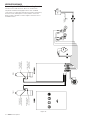
WIRING DIAGRAMS
Connecting the 9100TS Twin Alternating Controls
The twin sensor and extension cables are used for twin
unit parallel and alternating applications. Four standard
connections are required for operation; the power transformer,
the flow sensor, motor/optical sensor, and the connection
between tank 1 and tank 2 controls. Figure 18 outlines these
standard features.
Figure 18
GREEN / YELLOW
BACKPLATE
GROUND
SCREW
TANK 1TANK 2
TOP CONDUCTIVITY
SENSOR PROBE
(SHORT LENGTH WIRE)
BOTTOM CONDUCTIVITY
SENSOR PROBE
(LONG LENGTH WIRE)
TOP CONDUCTIVITY
SENSOR PROBE
(SHORT LENGTH WIRE)
BOTTOM CONDUCTIVITY
SENSOR PROBE
(LONG LENGTH WIRE)
16 • FLECK 9100TS Upflow

12
9
20
11
4
7
2
29
19
15
16
14
17
8
1
22
3
6
2
7
5
10
18
8
8
23
18
13
24
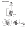
25
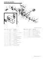
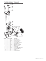
POWERHEAD ASSEMBLY
Item No. QTY Part No. Description
1.................1 ........ 15131 .................Backplate, 9000
2.................2 ........ 18728 .................Nut, Clip, #8-32
3.................1 ........ 44147 .................Transformer, US, 24V, 9.6VA, Lvl6
4.................1 ........ 15135 .................Gear, Drive
5.................1 ........ 14896 .................Wheel, Geneva
6.................2 ........ 40422 .................Nut, Wire, Tan
7.................2 ........ 19367 .................Screw, Designer Cover, Thumb
8.................2 ........ 14917 .................Retaining Ring, External
9.................1 ........ 15133 .................Drive Gear Assembly - Upper
10 ...............1 ........ 15810 .................Retaining Ring
11 ...............1 ........ 43091 .................Cam, Triple 9100TS
12 ...............2 ........ 15372 .................Washer, Thrust
13 ...............2 ........ 19160 .................Screw, #6-32 x 3/8 Pan Head
14 ...............2 ........ 15172 .................Scrw, Flat Head
15 ...............2 ........ 10340 .................Washer, Lock #4, Zinc
16 ...............2 ........ 16433 .................Switch, Micro Low DB
17 ...............2 ........ 15692 .................Washer, Plain, 3/8"
18 ...............1 ........ 18737 .................Drive Motor -24V, 50-60 Hz
19 ...............2 ........ 10339 .................Nut, Hex, 4-40 Zinc Plated
20 ...............1 ........ 15134 .................Drive Gear Assembly - Lower
22 ...............1 ........ 13547 .................Strain Relief, Cord
23 ...............1 ........ 42296 .................Plate, Ground, 9000/9500
24 ...............1 ........ 61787 .................Cover and PCB Assy, 9100TS
25 ...............1 ........ 19474 .................Harness, Power, 5600SE, Elect
Item No. QTY Part No. Description
BR61501-9100TS Rev D
FLECK 9100TS Upflow • 17

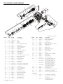
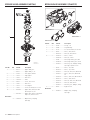
9100 CONTROL VALVE ASSEMBLY
18
42
45
27
19
28
48
47
5
21
49
25
24
41
38
22
37
30
29
31
39
32
33
35
34
46
1
40
40
36
23
26
20
9
10
6
15
14
12
13
11
8
7
4
3
2
7
16
8
10
11
9
14
15
13
17
3
2
50
51
52
53
54
55
BR61500-9100 Rev D
Item No. QTY Part No. Description
1.................1 ........ 40688 .................Valve Body Assy
2................16 ....... 13242-02 ............Seal
3................12 ....... 14241 .................Spacer
4.................1 ........ 16595 .................Spacer
5.................4 ........ 15137 .................Screw, Hex Washer Head
6.................1 ........ 14914 .................Piston, Upper
7.................2 ........ 14309 .................Retainer, Piston Rod
8.................2 ........ 14919 .................Piston, Rod, Upper
9.................2 ........ 13243 .................Plug, End
10 ...............2 ........ 13008 .................Retainer, End Plug Seal
11 ...............2 ........ 10209 .................Quad Ring, -010
12 ...............1 ........ 14921 .................Link, Piston Rod
13 ...............2 ........ 11335 .................Screw, #4-40
14 ...............2 ........ 13296 .................Screw, STL. Hex WSH, 6-20 x 3/8
15 ...............2 ........ 13363 .................Washer, Hague Drive
16 ...............1 ........ 61796 .................Piston Lower
17 ...............1 ........ 15019 .................Link, Piston Rod
18 ...............1 ........ 41500 .................O-ring, Drain
19 ...............1 ........ 15215 .................Body, Injector
20 ...............2 ........ 13301 .................O-ring, -011
21 ...............1 ........ 10913-000 ..........Nozzle, Injector, #000, Brown
22 ...............1 ........ 10914-000 ..........Throat, Injector, #000, Brown
23 ...............1 ........ 13303 .................O-ring, -021
24 ...............1 ........ 13387 .................Screw, Hex, Slotted
25 ...............1 ........ 43068 .................Screw, Hex WSH HD
26 ...............1 ........ 15348 .................O-ring, -563
27 ...............1 ........ 13173 .................Retainer, DLFC Button
28 ...............1 ........ 12087 .................Washer, Flow, 2.0 gpm
29 ...............1 ........ 14925 .................Brine Valve Stem
30 ...............1 ........ 12626 .................Seat, Brine Valve
31 ...............1 ........ 13167 .................Spacer, Brine Valve
32 ...............1 ........ 13165 .................Cap, Brine Valve
33 ...............1 ........ 11973 .................Spring, Brine Valve
34 ...............1 ........ 11981-03 ............Ring, Retaining, Copper
35 ...............1 ........ 16098 .................Washer, Nylon Brine
36 ...............1 ........ 12977 .................O-ring, -015
37 ...............1 ........ 13245 .................Retainer, BLFC
38 ...............1 ........ 17307 .................Washer, Flow Control, .12 gpm
39 ...............1 ........ 12550 .................Quad Ring, -009
40 ...............2 ........ 13302 .................O-ring, -014
41 ...............1 ........ 13244 .................Adapter, BLFC
42 ...............1 ........ 13497 .................Air Disperser, Injector
43 ...............1 ........ 13333 .................Label, Injector
44 ...............1 ........ 19654 .................Label, .125 gpm
45 ...............1 ........ 13361 .................Spacer
46 ...............1 ........ 40538 .................Retainer, 32 mm, O-ring Dist
47 ...............1 ........ 14906 .................Plate, End
48 ...............1 ........ 14928 .................Plug, End Stub
49 ...............1 ........ 60285-01 ............Injector Cap Assy
50 ...............1 ........ 61794-0624 ........Injector Drain, 9100TS, .125
BLFC, #000 Inj, 1.5 DLFC
............................ 61794-0634 ........Injector Drain, 9100TS, .125
BLFC, #000 Inj, 2.0 DLFC
............................ 61794-0644 ........Injector Drain, 9100TS, .125
BLFC, #000 Inj, 2.4 DLFC
............................ 61794-0562 ........Injector Drain, 9100TS, .125
BLFC, #000 Inj, 2.4 DLFC
51 ...............1 ........ 60125 .................Seal & Spacer Kit, Top
52 ...............1 ........ 60400 .................Piston Assy, Top
53 ...............1 ........ 61785 .................9100 Upper Piston Kit w/Seal Kit
54 ...............1 ........ 60421 .................Seal & Spacer Kit, Bottom
55 ...............1 ........ 61786 .................9100 Lower Piston Kit w/Seal Kit
Not Shown:
..................1 ........ 19054 .................O-ring, 32mm, -124, EPDM
..................1 ........ 18569 .................Retainer, Tank Seal (included
with Item 1)
..................1 ........ 18303 .................O-ring, Top of Tank, -336,
(included with iItem 1)
Item No. QTY Part No. Description
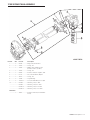
18 • FLECK 9100TS Upflow

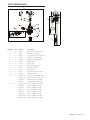
Item No. QTY Part No. Description
1.................4 ........ 40678 .................Ring, 9100, Yoke Retainer
2.................4 ........ 13287 .................O-ring, -123
3.................1 ........ 14865 .................Adapter Assy, 2nd Tank, 9100
(Includes Items 4, 5, and 7)
4.................1 ........ 19054 .................O-ring, -124
5.................1 ........ 40538 .................Retainer, 32mm, O-ring Dist, 7000
6.................1 ........ 61419 .................Kit, 1.05" Distributor, Adapter
7.................1 ........ 18303 .................O-ring, -336
8.................4 ........ 13255 .................Clip, Mounting
9.................4 ........ 14202-01 ............Screw, Hex Wsh Mach, 8-32 x 5/16
10 ...............1 ........ 60425-7 ..............Tube Assy, 9100, 7" Tank
............................ 60425-9 ..............Tube Assy, 9100, 8-9" Tank
............................ 60425-12 ............Tube Assy, 9100, 6-12" Tank
............................ 60425-16 ............Tube Assy, 9100, 13-16" Tank
Not Shown:
..................1 ........ 18569 .................Retainer, Tank Seal (Included with
Item 3)
10
9100 SECOND TANK ASSEMBLY
FLECK 9100TS Upflow • 19

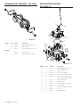
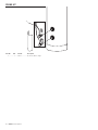
TURBINE METER ASSEMBLY - P/N 60626
Item No. QTY Part No. Description
1.................1 ........ 19797 .................Meter Assy, 3/4" Dual Port, SLP
2.................2 ........ 19569 .................Clip, Flow Meter
3.................2 ........ 13314 .................Screw, Slot Ind Hex, 8-18 x 0.60
Not Shown:
......... 14613 .................Flow Straightener
......... 19791-01 ............Meter Cable Assy, Turbine/SE
BR60626
2
3
1
PADDLE METER ASSEMBLY -
P/N 60086-50
Item No. QTY Part No. Description
1.................1 ........ 14716 .................Meter Cap Assy, NT (includes
items 2, 3, and 4)
2.................1 ........ 13874 .................Cap, Meter, Electronic
3.................1 ........ 13847 .................O-ring, -137, Std, Meter
4.................1 ........ 17798 .................Screw, Slot Hex Washer Head
5.................1 ........ 19791-01 ............Meter Cable Assy, Turbine/SE
(not included in P/N 60086-50)
6.................1 ........ 13821 .................Body, Meter, 5600
7.................1 ........ 13509 .................Impeller, Meter
8.................4 ........ 12473 .................Screw, Hex Wsh, 10-24 x 5/8
9.................4 ........ 13255 .................Clip, Mounting
10 ...............4 ........ 13314 .................Screw, Slot Ind Hex, 8-18 x 0.60
11 ...............4 ........ 13305 .................O-ring, -119
12 ...............1 ........ 14613 .................Flow Straightener
5
8
1
2
7
6
9
10
3
4
11
BR60086 Rev E
20 • FLECK 9100TS Upflow
Page is loading ...
Page is loading ...
Page is loading ...
Page is loading ...
Page is loading ...
Page is loading ...
Page is loading ...
Page is loading ...
Page is loading ...
Page is loading ...
Page is loading ...
Page is loading ...
-
 1
1
-
 2
2
-
 3
3
-
 4
4
-
 5
5
-
 6
6
-
 7
7
-
 8
8
-
 9
9
-
 10
10
-
 11
11
-
 12
12
-
 13
13
-
 14
14
-
 15
15
-
 16
16
-
 17
17
-
 18
18
-
 19
19
-
 20
20
-
 21
21
-
 22
22
-
 23
23
-
 24
24
-
 25
25
-
 26
26
-
 27
27
-
 28
28
-
 29
29
-
 30
30
-
 31
31
-
 32
32


Ask a question and I''ll find the answer in the document
Finding information in a document is now easier with AI
Related papers
-
Fleck 5800LXT Owner's manual
-
-
Pentair Whole House Softening Owner's manual
-
-
Fleck Fleck7000SXT Owner's manual
-
-
-
-
-
Other documents
-
Whirlpool ADG 4550/2 IX User guide
-
Whirlpool ADG 689/3 IX User guide
-
 Canature WS685HEC Owner's manual
-
-
-
 Water Right Sanitizer Plus ASP2-1044 Installation Instructions & Owner's Manual
-
-
Clean Water Commercial Water Softener 9510 120K 4.0 CF Installation guide
-
Hellenbrand ProMate DMT Series Owner's manual
-
 Tahoe T../MA-BTB series Installer Manual


