Page is loading ...

Revision A
300387005INS
November 1, 2004
IMI Cornelius Inc; 2004
IMI CORNELIUS INC.
Telephone (800) 238–3600
www.cornelius.com
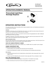
INSTALLATION MANUAL
Liquid Base Beverage Dispenser
DRIP
TRAY
CUP
REST
FRONT
ACCESS PANEL
SUPPLY INLET
Design data
Width 7 1/2”
Height 17 1/2”
Depth 9 1/8”
Electrical Requirements:(if applicable)
15 Amp Circuit, 115v 60hz
.52 Amp Unit Current Draw
24v 60hz, Dispensing valves
Installation Check List :
Counter Top with access to route
concentrate supply lines.
15 Amp,115v60hz Outlet, Within 5’
(if applicable)
Cold Water Supply, With Shutoff
Overall Dimensions:
Weight: 9 lbs
24 VOLT
TRANSFORMER
(24 Volts) cord to
dispensing valves
RECEIVING
Each Unit is completely tested under operating conditions and thoroughly inspected before shipment. At time of
shipment, the carrier accepts the Unit and any claim for damage in transit must be made with the carrier. Upon
receiving Unit from the delivering carrier, carefully inspect the carton for visible indication of damage. Any dam-
age or irregularities should be noted at time of delivery (or not later than 15 days from date of delivery) and im-
mediately reported to the delivering carrier. Request a written inspection report from the Claims Inspector to
substantiate claim. File claim with the delivering carrier, not with IMI Cornelius Inc.
INSTALLATION
Place Unit in selected location to install unit.
Use mounting template (See page No. 3), to drill mounting holes for installing unit to counter top.
Manufacturer requires the use of all 6 bolt locations on the template to fasten to countertop.
Liberally apply a sealant, such as Dow Corning RTV 731 or equivalent, to the unit flange bottom surface,per
(NSF) requirements, the unit must be sealed to the counter top.
Make connections as follows:
Plain Water Source Connections:
TO THE INSTALLER
It is the responsibility of the installer to ensure that the water supply to the dispensing equipment is
provided with protection against backflow by an air gap as defined in ANSI/ASME A112. 1.2-1979; or an
approved vacuum breaker or other such method as proved effective by test.
Water pipe connections and fixtures directly connected to a potable water supply shall be sized,
installed, and maintained according to Federal, State, and Local laws.

2
300387005INS
1. Flush plain water source thoroughly before connecting to Unit.
2. Connect plain water source to water inlet tube labeled ‘‘WATER’’.
Concentrate Line Connection:
1. Connect concentrate source lines to inlet lines from dispenser, labeled ‘‘1 or 2 etc.’’. DO NOT CONNECT
SOURCE LINES TO CONCENTRATE AT THIS TIME.
Transformer Connections: (for electric valve units)
1. Connect Unit cord two-pin connector to the mating connector on the transformer output (24V) cord.
Steps of final installation:
1. Plug transformer into electrical outlet with proper electrical requirements.
2. Open shutoff valve in plain water source line.
3. Inspect connections for leaks.
4. Place a waste container under each nozzle and operate valve(s) to remove air from the plain water line.
5. Connect concentrate supply to concentrate system.
6. Open cylinder shutoff valve to apply the calculated pressure (approx. 40 PSI) to the concentrate system.
7. Operate each dispensing valve to remove air from the lines.
8. Check all lines for leaks.
9. Adjust Dispensing Valves for Water-To-Concentrate “Ratio” of dispensed drinks as instructed on ”BRIXING
VALVES” instructions.
NOTE: Concentrate system must be sanitized before Unit is put into operation. Refer to
Owner/Operator Manual for procedure.
10. Apply flavor decals to valve covers.
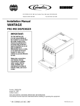
ONE SINGLE-FLAVOR
DISPENSING VALVE
ADJUSTABLE CONCENTRATE
FLOW REGULATOR
1
2
CONCENTRATE NO. ”2” IN
CONCENTRATE NO. ”1” IN
”WATER” IN
TWO SINGLE-FLAVOR
DISPENSING VALVES
1
2
3
4
”WATER” IN
CONCENTRATE NO. ”1” IN
CONCENTRATE NO. ”3” IN
CONCENTRATE NO. ”4” IN
TWO TWO-FLAVOR
DISPENSING VALVES
ADJUSTABLE WATER
FLOW REGULATOR
CONCENTRATE NO. ”2” IN
FLOW DIAGRAMS
”WATER” IN
CONCENTRATE NO. ”1” IN
”WATER” IN
”WATER” IN
1
2
3
4

3
300387005INS
CUT–OUT FOR THRU COUNTERTOP
INLET LINE HOOKUP
5/16” HOLE (6)
OUTSIDE BASE OF LBBD
FRONT OF UNIT
2”X4-1/2”
LBBD MOUNTING TEMPLATE
WITH BASE DIM. OF 7–1/4” X 9”
/