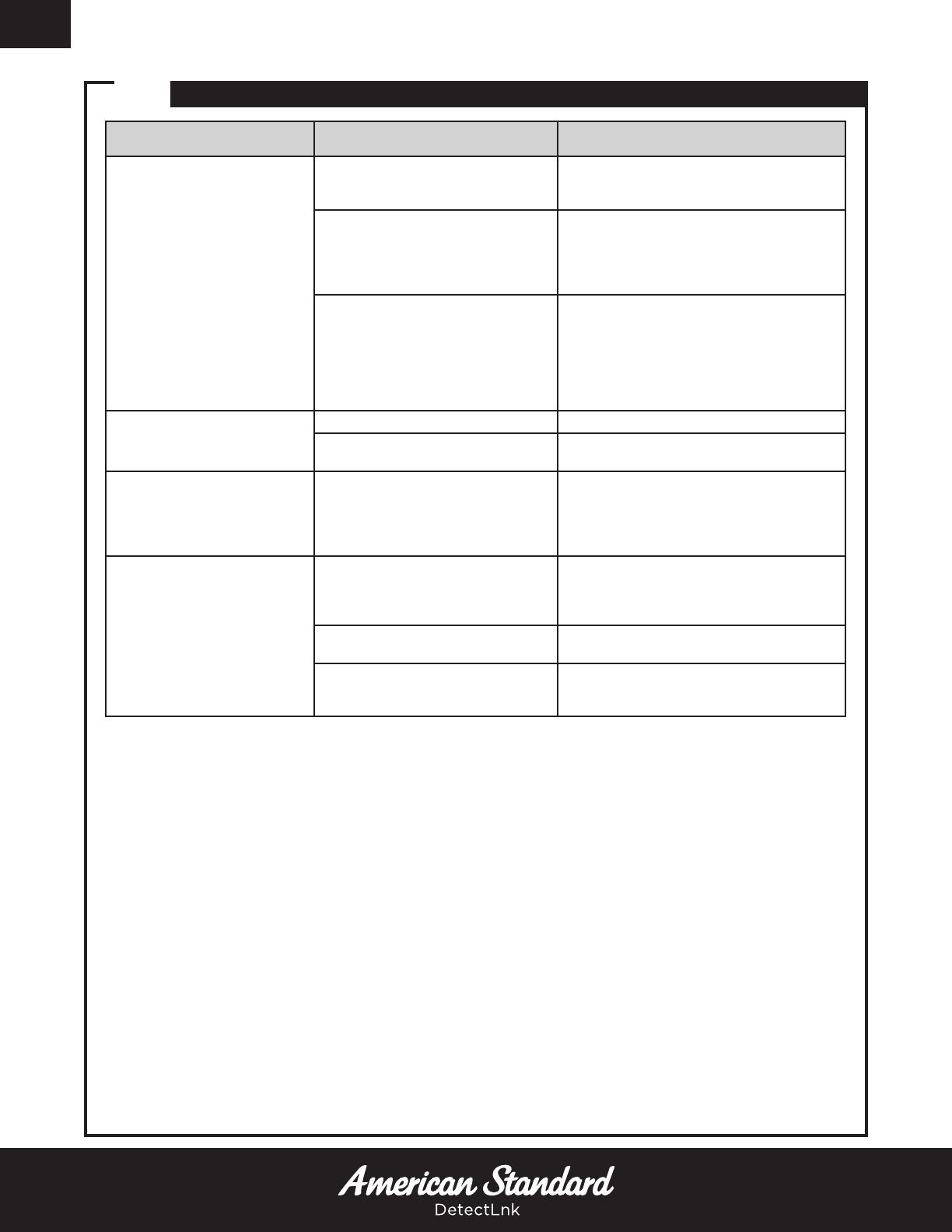
18 TROUBLESHOOTING: TOILET/URINAL FLUSH VALVE
PROBLEM POSSIBLE CAUSE CORRECTIVE ACTION
Valve will not operate.
Stop valve is closed. Open stop valve.
Supply valve is closed. Open supply valve.
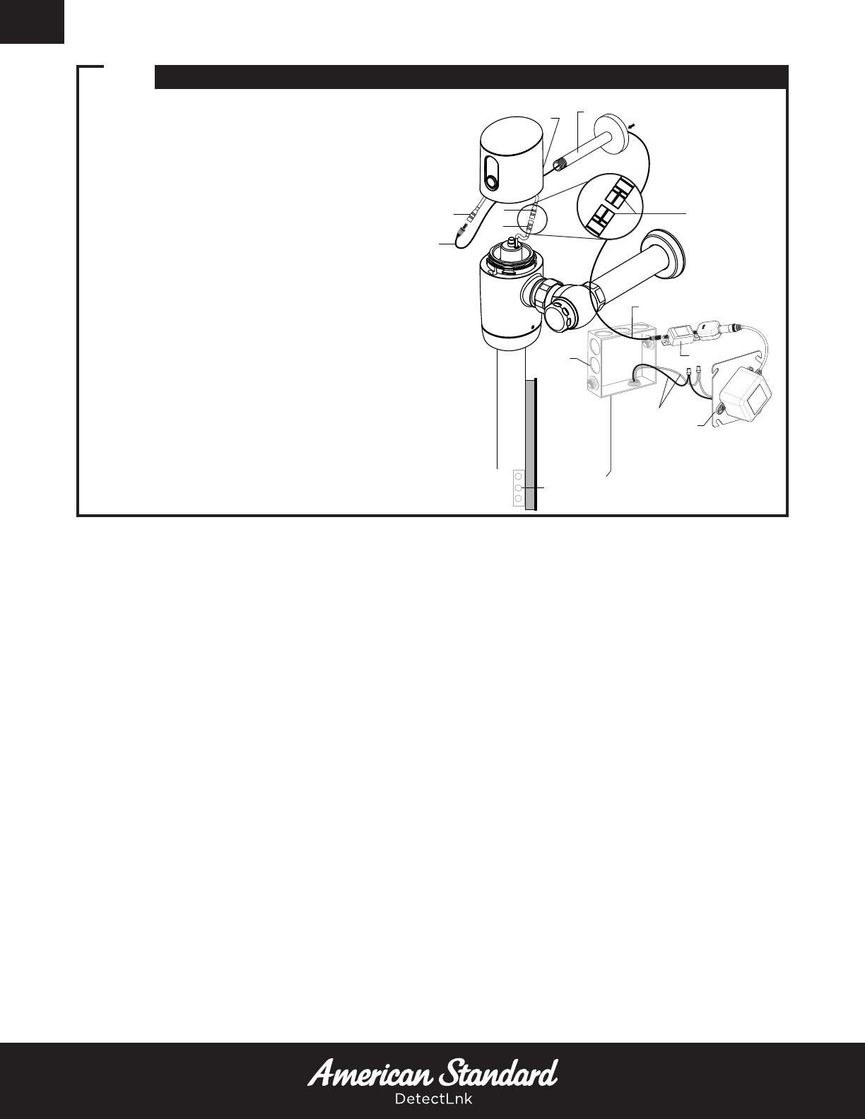
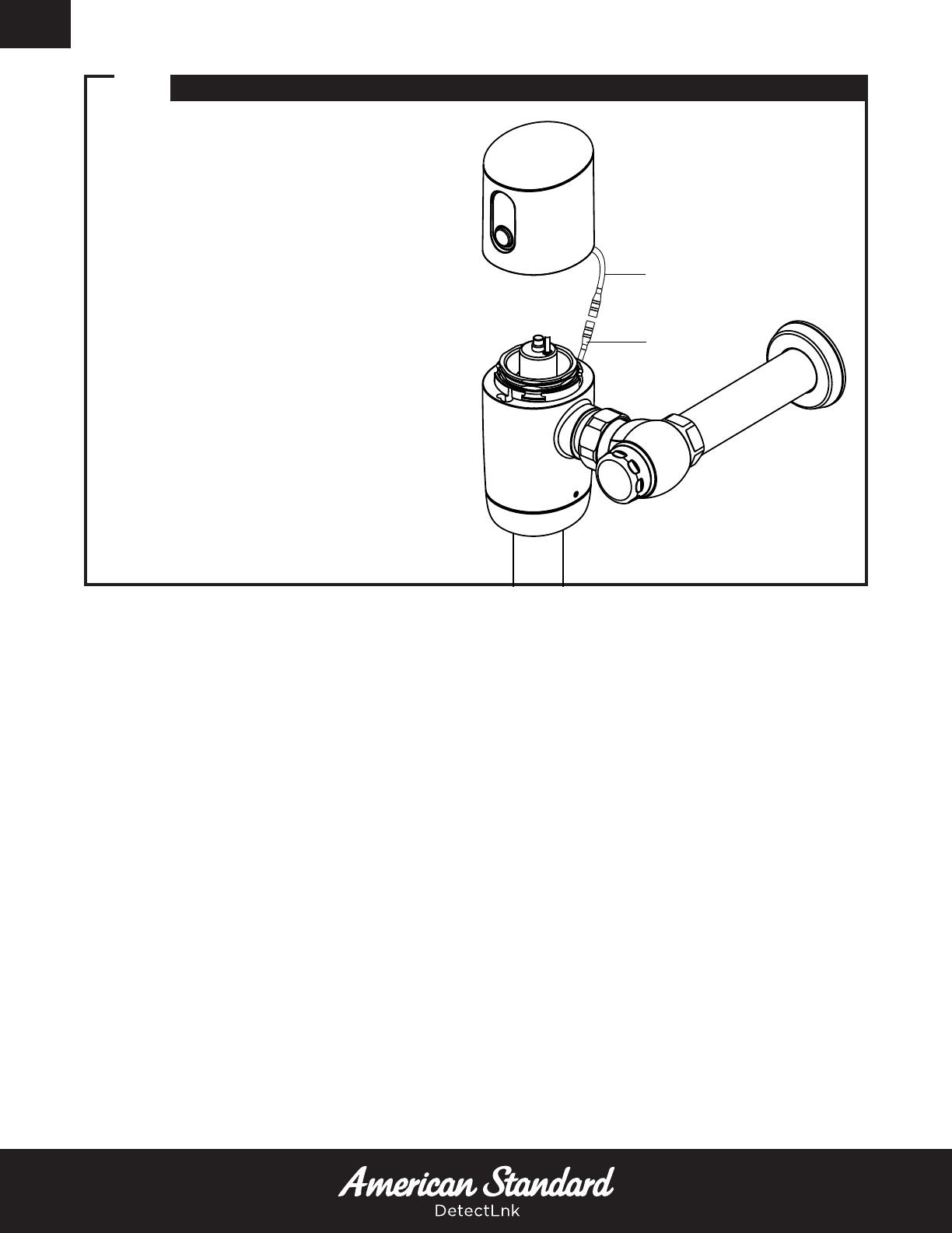
Battery/The electric wire(s) is not
connected. Connect the wires.
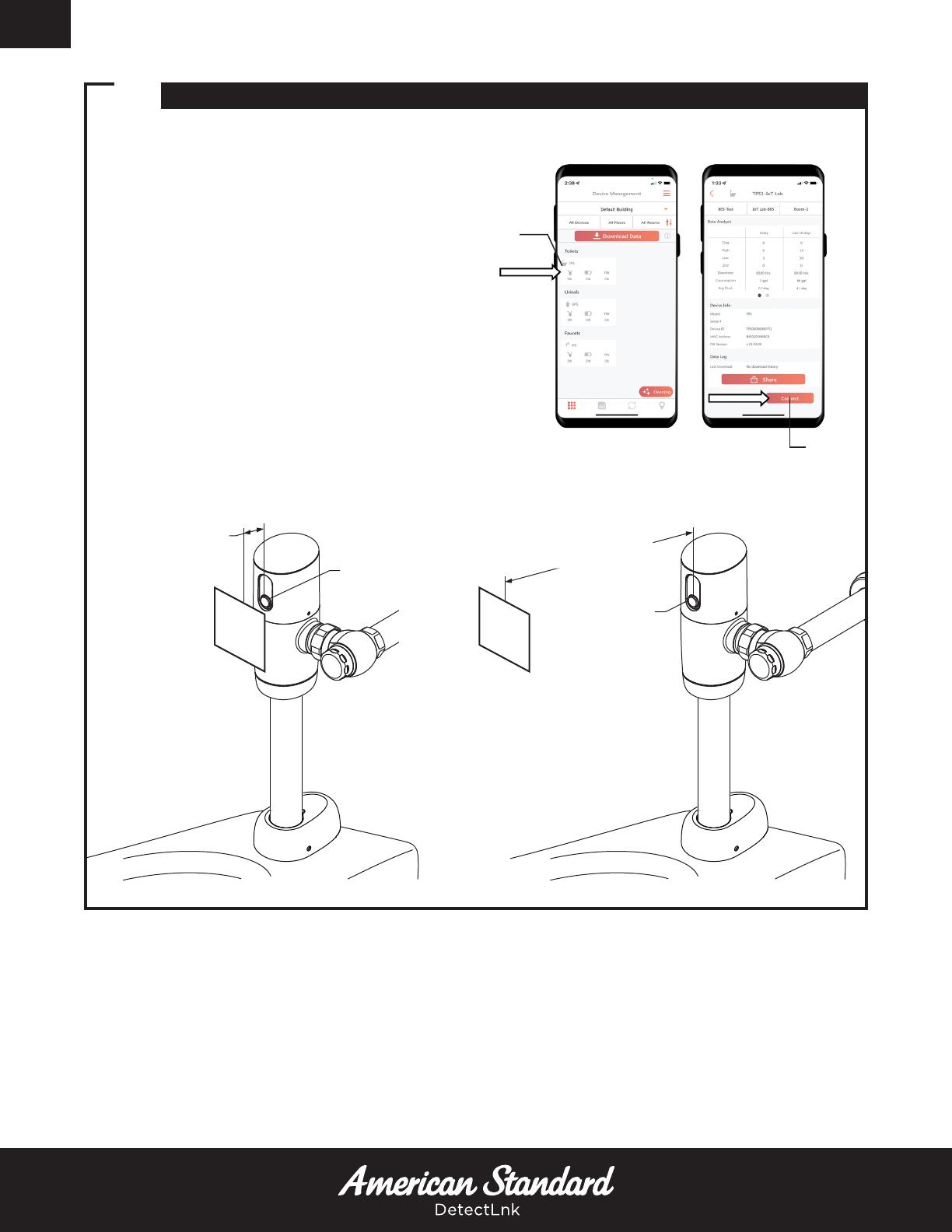
Sensor lens is dirty. Clean lens.
Reflective surface in front of sensor. Remove the reflective surface from in front
of the sensor.
Detection range not adjusted
properly. Adjust the detection range.
The infrared sensor or the actuator is
out of order. Contact distributor for replacement.
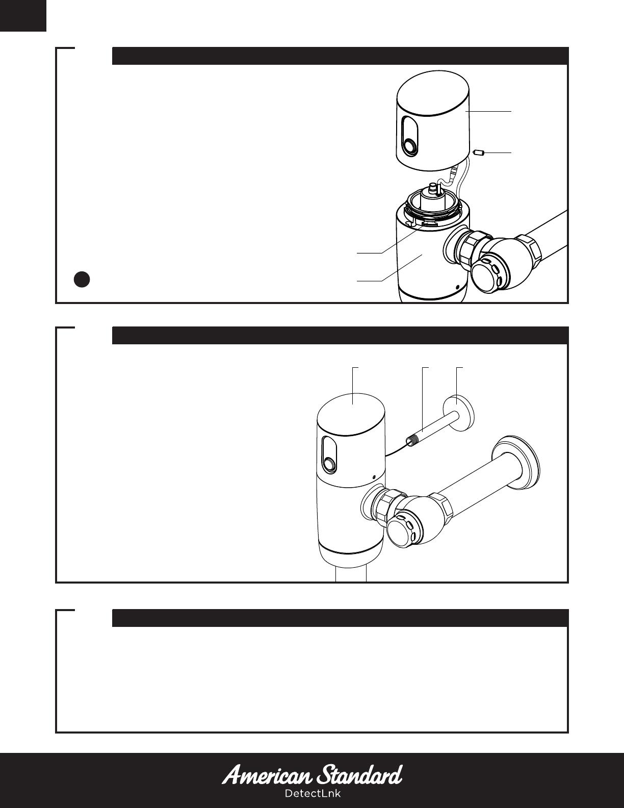
Battery is critical.
Press the button for 3-5 seconds. If LED
does not blink blue, the battery is critically
low and needs to be replaced.
Flush Valve Electronic is faulty. Replace Flush Valve Electronic.
No power provided by battery/
power supply. Replace battery/power supply.
Flush valve does not activate
after user leaves.
Sensor does not recognize a user. Using the DetectLnkTM app, enter the
device settings and adjust IR Distance.
Battery/Power Supply is disrupted.
Verify connection to sensor.
Check available voltage where Battery/
Power supply is connected with sesnor with
DC voltmeter. 5.8 to 6.5 VDC is required.
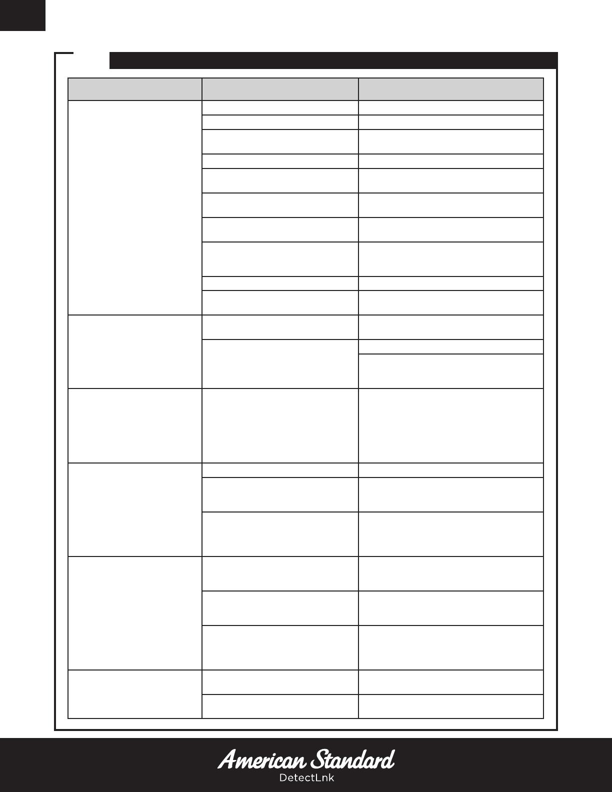
Unit is constantly flushing. Solenoid may be stuck open.
Press the button for at least 3-5 sec.
If the LED starts blinking blue, but the water
does not stop, the Solenoid needs to be
replaced.
If the LED does not blink blue and water
does not stop, the Battery needs to be
replaced.
Insufficient volume of water
to adequately fixture.
Stop valve is not open enough. Open stop valve for desired volume of water.
Insufficient flow rate or pressure at
supply line.
Consult fixture guide for minimum gallons
per minute flow and running pressure for
satisfactory performance.
Water pressure is lower than
recommended.
Fully open the angle stop, then using the
DetectLnkTM app, enter the device settings
and increase the flush durations. Test at
every 0.125 sec. increment.
Valve is flushing too long
or not shutting off.
Trip mechanism not seating
properly due to foreign material
between trip mechanism and seat.
Disassemble parts and rinse thoroughly.
By-pass orifice is plugged or partially
plugged.
Examine by-pass orifice and clean if
necessary, being certain not to enlarge
orifice opening.
Line pressure is not adequate to
force trip mechanism to seal.
Pressure is inadequate or has dropped
below minimum operating range.
Steps should be taken to increase the line
pressure.
Water splashes out of fixture.
Supply flow rate is higher than is
necessary. Adjust downward on control stop.
Lime accumulation on vortex or
spreader holes of fixture. Remove the lime build up.