Page is loading ...

Keep accessible for future reference
Instruction
AS-477
Acceleration sensor

Copyright © 2021 Brüel & Kjær Vibro GmbH
All rights to this technical documentation remain reserved.
Any corporeal or incorporeal reproduction or dissemination of this technical documentation or making this
document available to the public without prior written approval from Brüel & Kjær Vibro GmbH shall be
prohibited. This also applies to parts of this technical documentation.
Instruction Sensor AS-477, C106002.002 / V07, en, date of issue: 30.11.2021
Brüel & Kjær Vibro GmbH
Leydheckerstrasse. 10
64293 Darmstadt
Germany
Phone: +49 6151 428 0
Fax: +49 6151 428 1000
Brüel & Kjær Vibro A/S
Lyngby Hovedgade 94, 5 sal
2800 Lyngby
Denmark
Phone: +45 69 89 03 00
Fax: +45 69 89 03 01
BK Vibro America Inc
1100 Mark Circle
Gardnerville NV 89410
USA
Phone: +1 (775) 552 3110
Homepage
www.bkvibro.com

© Brüel & Kjær Vibro ● C106002.002 / V07 ● Page 3 of 14
Technical alterations reserved!
Brüel & Kjær Vibro │Instruction Sensor AS-477
Table of Contents
EN
UNRESTRICTED DOCUMENT
Table of Contents
1 Hint ............................................................................................................................ 4
1.1 Pictograms and their Meanings .......................................................................................................... 4
1.2 User Qualification ................................................................................................................................. 4
1.3 Intended Use ......................................................................................................................................... 5
1.3.1 Recommendations to User ..................................................................................................................................... 5
1.3.2 Prohibition of Unauthorized Modifications .............................................................................................................. 5
2 Application ............................................................................................................... 6
3 Measuring Principle ................................................................................................. 6
4 Mounting .................................................................................................................. 6
4.1 Coupling ................................................................................................................................................ 6
5 EMV ........................................................................................................................... 7
6 Calibration ................................................................................................................ 7
7 Disposal .................................................................................................................... 7
8 Technical Data ......................................................................................................... 8
9 Connection Diagram .............................................................................................. 11
10 CE Declaration ....................................................................................................... 12

Page 4 of 14 © Brüel & Kjær Vibro ● C106002.002 / V07
Technical alterations reserved!
EN
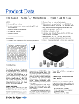
1 Hint
Figure 1-1) Acceleration sensor AS-477
NOTE!
This manual is a part of the product. Read the manual carefully before using the product
and keep it accessible for future use.
1.1 Pictograms and their Meanings
This symbol warns of dangerous situations which can result from misuse of the product.
1.2 User Qualification
Ensure that all work in conjunction with our systems is performed by skilled, expert and authorized
workers (for ATEX systems according to EN 60079-14). Among these works are:
Installation and Commissioning
Installation and commissioning primarily concern work on electrical equipment. These works may be
performed exclusively by electricians or workers instructed and supervised by an electrician in
accordance with electrotechnical regulations/directives.
Change of System Specification
Any change of system specification has its effects on monitoring process with stationary systems and
on the measuring sequence with portable measuring systems.

© Brüel & Kjær Vibro ● C106002.002 / V07 ● Page 5 of 14
Technical alterations reserved!
Brüel & Kjær Vibro │Instruction Sensor AS-477
Hint
EN
UNRESTRICTED DOCUMENT
1.3 Intended Use
If sensors and cables are used in a way not described in the relevant user manuals, function and
protection may be impaired and serious personal damage, death or serious, irreversible injuries may
result.
• Exclusively use sensor as specified in data sheet. Any use other than specified is considered
inappropriate. Brüel & Kjær Vibro does not assume any liability for damages resulting from
inappropriate use. The user is solely responsible.
• Mounted sensors must not be used as steps.
• Ensure that system is exposed only to admissible environmental influences specified in
technical system data sheet.
• Maintain electrical equipment in regular intervals. Remedy defects, e.g. loose wires, defective
connectors, immediately.
Hot surfaces
• In line with the user manuals, sensors and cables can be operated in extensive ambient
temperature ranges, whereby they can become hot through self-heating on housing walls and
can produce burning.
• When mounted at external heat or cold sources (e.g. machine parts), systems, sensors and
cables can adopt dangerous temperatures, whereby burning, among other things, can occur in
the event of contact.
1.3.1 Recommendations to User
If the use of the system in conjunction with machines or plant sections can produce risks outside of
Brüel & Kjær Vibro's responsibility, the user is expected to prepare and distribute safety technical
instructions or warnings and to ensure that the personnel concerned has received and understood it.
If system is integrated into a machine or designed to be assembled, commissioning must
not take place until the machine the system is to be integrated in conforms to the EC
directives.
1.3.2 Prohibition of Unauthorized Modifications
System and accessories must not be changed neither in construction nor safety technology without
the express consent of Brüel & Kjær Vibro. Any unauthorized modification excludes Brüel & Kjær
Vibro's liability for resulting damages.

Page 6 of 14 © Brüel & Kjær Vibro ● C106002.002 / V07
Technical alterations reserved!
EN
2 Application
The AS-477 is mainly used for measurement of vibrations at rotating machines such as turbines,
pumps, compressors, etc.
3 Measuring Principle
The acceleration sensor operates according to the piezo-electric principle. A piezo-element and an
internal sensor mass form a spring-mass system in the sensor.
If this system is subjected to vibrations the mass produces an alternating force on the piezo element.
As a result of the piezo effect an electrical charge is produced that is proportional to vibration
acceleration.
An integrated amplifier converts this charge signal into a usable voltage signal.
4 Mounting
4.1 Coupling
General rule:
The weight of the acceleration sensor should always be lower at least by a factor ten than the weight
of the object onto which it is mounted.
The acceleration sensor is an additional mass, which loads the object on which it is mounted, and this
changes the vibration behaviour if it is too large. The sensor requires a friction-locked, contact
resonance-free, rigid mounting to the object, particularly for measurements at high frequencies. The
cable must be attached on a non-tension basis and load-free in connection.
Figure 4-1) Mounting (all length in [mm])
Acceleration Sensor AS-477
Threaded stud secured
with Locite
Mounting surface

© Brüel & Kjær Vibro ● C106002.002 / V07 ● Page 7 of 14
Technical alterations reserved!
Brüel & Kjær Vibro │Instruction Sensor AS-477
EMV
EN
UNRESTRICTED DOCUMENT
The sensor is to be installed with the threaded stud (¼“– 28 UNF on M8X1,25) included.
It can be installed in any orientation on the machine.
1.
The mounting surface must be machined flat in the area of the sensor (roughness depth
0.8 µm) and have a minimum diameter of 28 mm.
2.
Supply installation surface with threaded bore M8X1,25 according to drawing (fig.4-1).
3.
The bore must be countersunk and cleaned.
4.
Screw threaded stud into installation surface according to drawing (fig. 4-1) and secure
(LOCTITE 243 intermediate strength or LOCTITE 270 high strength).
5.
Apply thin layer of silicone grease to the installation surface to reduce contact resonance.
6.
Screw sensor onto the threaded stud with a mounting torque of 3.5 Nm
(key width 7/8” / 22.2 mm) and secure (LOCTITE 243 medium strength or LOCTITE 270 high
strength).
5 EMV
EN 61326-1
Through electromagnetic stray fields, influences on the measured values may arise. In case of
disturbing influences of this type, a grounded protective conduit is recommended for the signal cable.
6 Calibration
In the event of a calibration request, we offer the following services:
• Factory calibration by Brüel & Kjær Vibro
• Calibration traceable to national standards by our DAkkS accredited calibration laboratory
7 Disposal
After use, dispose of the systems, cables and sensors in an
environmentally friendly manner, in accordance with the applicable
national provisions.
WEEE-Reg.-Nr. DE 69572330

Page 8 of 14 © Brüel & Kjær Vibro ● C106002.002 / V07
Technical alterations reserved!
EN
8 Technical Data
Features
High sensitivity
Suitable for slowly rotating
machinery
Robust design
M12 plug
Constant current supplied
Applications
The sensor is suitable for the recording of high and low frequency signals. Typical applications are,
for example, the monitoring of transmissions or cooling fans in wind turbines, heavy-duty and
planetary gears or large fans.
Product description
Scope of delivery:
• Sensor AS-477
• 1 x Threaded bolt ¼“ – 28 UNF to M8X1,25
• Documentation
Connection
Plug connection
(M12 male)
Pin 1: + (SIG)
Pin 2: - (0V / GND)
Pin 3: not connected
Pin 4: not connected
Length in [mm]

© Brüel & Kjær Vibro ● C106002.002 / V07 ● Page 9 of 14
Technical alterations reserved!
Brüel & Kjær Vibro │Instruction Sensor AS-477
Technical Data
EN
UNRESTRICTED DOCUMENT
The following performance data apply, to the extent that nothing else is indicated, under standard conditions
(Ambient temperature = 25 °C, Constant current = 4 mA).
Dynamic
Sensitivity, nom. (at 100 Hz): 500 mV/g ±5 %
Frequency response: 0,2 Hz .. 14 kHz: ±3 dB
0,7 Hz .. 5 kHz: ±5 %
Measurement range: 10 g Peak
Resonance frequency: min. 25 kHz, typically 30 kHz
Amplitude linearity: < 1 %
Cross sensitivity: < 5 %
Electric
Maximum output voltage: 30 V
Constant current supply
(secure against reverse polarity): 2 mA .. 10 mA (24 V nom.)
Broadband noise (2.5 Hz .. 25 kHz): 250 µg
Spectral noise: 10 HZ: 2,5 µg /√HZ
100 HZ: 1,5 µg /√HZ
1000 HZ: 1,5 µg /√HZ
Output resistance: 300
Bias voltage, typically: 12,5 VDC
Across entire temperature range: 10 V - 14 V
Grounding: Housing isolated against sensor electronic
Surroundings
Operating temperature range: -50 °C ... +120 °C
Operating temperature
with connection cable AC-140…: -30 °C ... +90 °C
Storage temperature range in original packaging: -20 °C ... +70 °C
Overload capacity: Constant, sinusoidal: 500 g
Schock: 5.000 g
Housing design: Hermetically sealed stainless steel housing
Degree of protection acc. EN 60529: IP67 / IP68 (incl. Nema 6)
(only with connection cable AC-1403 or AC-1404)
Physical values
Measurement principle: Piezoelectric principle, shear type
Weight: 90 g
Housing material: 316 L stainless steel
Thread: ¼“ – 28 UNF
Mounting torque: 3,5 Nm (width across flats: 7/8” / 22,2 mm)
Connection: M12 plug (male, 4-pole)

Page 10 of 14 © Brüel & Kjær Vibro ● C106002.002 / V07
Technical alterations reserved!
EN
Order code
AS-477
Accessories
AC-1403: double-wired connection cable with straight plug (M12)
AC-1404: double-wired connection cable with angled plug (M12)
AC-3360: threaded bolt, 1/4" – 28 UNF to M8x1,25
AC-3362: threaded bolt, 1/4" – 28 UNF to 1/4" – 28 UNF

© Brüel & Kjær Vibro ● C106002.002 / V07 ● Page 11 of 14
Technical alterations reserved!
Brüel & Kjær Vibro │Instruction Sensor AS-477
Connection Diagram
EN
UNRESTRICTED DOCUMENT
9 Connection Diagram

Page 12 of 14 © Brüel & Kjær Vibro ● C106002.002 / V07
Technical alterations reserved!
EN
10 CE Declaration

© Brüel & Kjær Vibro ● C106002.002 / V07 ● Page 13 of 14
Technical alterations reserved!
Brüel & Kjær Vibro │Instruction Sensor AS-477
CE Declaration
EN
UNRESTRICTED DOCUMENT

Contact
Brüel & Kjær Vibro GmbH
Leydheckerstrasse 10
64293 Darmstadt
Germany
Phone: +49 6151 428 0
Fax: +49 6151 428 1000
Brüel & Kjær Vibro A/S
Lyngby Hovedgade 94, 5 sal
2800 Lyngby
Denmark
Phone +45 69 89 03 00
Fax: +45 69 89 03 01
BK Vibro America Inc
1100 Mark Circle
Gardnerville NV 89410
USA
Phone: +1 (775) 552 3110
Corporate E-Mail: [email protected]
Homepage: www.bkvibro.com
Sensor AS-477 ● © Brüel & Kjær Vibro ● 11/2021 ● C106002.002 / V07 ●
Technical alterations reserved!
/