Dwyer 2000 Series User manual

Type
User manual

The Dwyer 2000 Series Magnehelic® Differential Pressure Gage is a versatile device designed to measure and display pressure differences in air and non-combustible, compatible gases. With its durable construction and accurate readings, it is ideal for various applications, including HVAC systems, clean rooms, laboratories, and industrial settings. The gage boasts a 4-inch dial face for easy readability and comes equipped with duplicate high and low-pressure taps for versatile connection options. Its rugged housing and acrylic cover ensure protection against harsh environments.

The Dwyer 2000 Series Magnehelic® Differential Pressure Gage is a versatile device designed to measure and display pressure differences in air and non-combustible, compatible gases. With its durable construction and accurate readings, it is ideal for various applications, including HVAC systems, clean rooms, laboratories, and industrial settings. The gage boasts a 4-inch dial face for easy readability and comes equipped with duplicate high and low-pressure taps for versatile connection options. Its rugged housing and acrylic cover ensure protection against harsh environments.

Magnehelic®Differential Pressure Gage
1/8 FEMALE NPT
HIGH PRESSURE
CONNECTION
1-3/4
(44.45)
1/2
(12.70)
1/8 FEMALE
NPT LOW
PRESSURE
CONNECTION
11/16
(17.46)
17/32
(13.49) ø4-3/4 (120.65) PANEL CUTOUT
ø5
(127)
ø4-47/64
(120.27)
3/16
(4.76)
2-17/32
(64.29)
15/32
(11.91)
ø4-1/2
(114.3)
1-1/4
(31.75)
ø5-1/2
(139.70)
MOUNTING RING
RUBBER PRESSURE RELIEF
PLUG WILL UNSEAT ITSELF
WHEN GAGE IS
OVERPRESSURIZED
(3) 6-32 X 3/16 (4.76) DEEP HOLES
EQUALLY SPACED ON A Ø4-1/8
(104.78) BOLT CIRCLE FOR
PANEL MOUNTING
1/8 FEMALE NPT
HIGH PRESSURE
CONNECTION
1-3/4
(44.45)
1/2
(12.70)
1/8 FEMALE NPT
LOW PRESSURE
CONNECTION
11/16
(17.46)
15/32
(11.91)
1-11/16
(42.86)
Ø4-1/2
(114.3)
1-1/4
(31.75)
17/32
(13.49)
.025 (.64) SPACE CREATED BY 3
SPACER PADS WHEN SURFACE
MOUNTED. DO NOT OBSTRUCT.
PROVIDES PATH FOR RELIEF OF
OVERPRESSURE.
1/8 FEMALE
NPT HIGH
PRESSURE
CONNECTION
1/8 FEMALE
NPT LOW
PRESSURE
CONNECTION
7/16
(11.11)
Ø4-3/4
(120.65)
Bulletin A-27
SPECIFICATIONS
Service: Air and non-combustible, compatible gases. (Natural
Gas option available.)
Wetted Materials: Consult factory.
Housing: Die cast aluminum case and bezel, with acrylic
cover. (MP model has polycarbonate cover).
Accuracy: 2% of full scale (±3% on -0, -100PA, -125PA,
-10MM and ±4% on -00, -60PA, -6MM), throughout range at
70°F (21.1°C); High accuracy version: ±1% on full scale
(±1.5% on -0, -100PA, -125PA, -10MM and ±2% on -00,
-60PA, -6MM).
Pressure Limits: -20˝ Hg to 15 psig.† (-0.677 bar to 1.034
bar); MP option: 35 psig (2.41 bar), HP option: 80 psig (5.52
bar).
Enclosure Rating: IP67.
Overpressure: Relief plug opens at approximately 25 psig
(1.72 bar), standard gages only. The blowout plug is not used
on models above 180 inches of water pressure, medium or
high pressure models, or on gages which require an elastomer
other than silicone for the diaphragm.
Temperature Limits: 20 to 140°F (-6.67 to 60°C).
*Low
temperature models available as special option.
Size: (101.6 mm) diameter dial face.
Mounting Orientation: Diaphragm in vertical position.
Consult factory for other position orientations.
Process Connections: 1/8˝ female NPT duplicate high and
low pressure taps - one pair side and one pair back.
Weight: 1 lb 2 oz (510 g), MP & HP 2 lb 2 oz (963 g).
Agency Approvals: RoHS.
†For applications with high cycle rate within gage total pressure rating,
next higher rating is recommended. See Medium and High pressure
options.
Note: May be used with hydrogen when ordering Buna-N diaphragm.
Pressure must be less than 35 psi.
STANDARD GAGE ACCESSORIES: Two 1/8˝ NPT plugs for
duplicate pressure taps, two 1/8˝ pipe thread to rubber tubing
adapters and three flush mounting adapters with screws.
MP AND HP GAGE ACCESSORIES: Mounting ring and snap
ring retainer substituted for 3 adaptors, 1/4” compression fittings
replace 1/8” pipe thread to rubber tubing adaptors.
OVERPRESSURE PROTECTION: Standard Magnehelic®
Differential Pressure Gages are rated for a maximum
pressure of 15 psig and should not be used where that limit
could be exceeded. Models employ a rubber plug on the rear
which functions as a relief valve by unseating and venting the
gage interior when over pressure reaches approximately 25
psig (excludes MP and HP models). To provide a free path for
pressure relief, there are four spacer pads which maintain .023˝
clearance when gage is surface mounted. Do not obstruct the
gap created by these pads.
*The blowout plug is not used on models above 180 inches of water pressure, medium or high pressure models,
or on gages which require an elastomer other than silicone for the diaphragm.
www.calcert.com sales@calcert.com1.888.610.7664 0
5
10
15
20
25
30
PIPE MOUNTING
To mount gage on 1-1/4” - 2” pipe, order optional A-610 pipe
mounting kit.
TO zERO GAGE AFTER INSTALLATION
Set the indicating pointer exactly on the zero mark, using the
external zero adjust screw on the cover at the bottom. Note that
the zero check or adjustment can only be made with the high
and low pressure taps both open to atmosphere.
OPERATION
Positive Pressure: Connect tubing from source of pressure to
either of the two high pressure ports. Plug the port not used.
Vent one or both low pressure ports to atmosphere.
Negative Pressure: Connect tubing from source of vacuum or
negative pressure to either of the two low pressure ports. Plug
the port not used. Vent one or both high pressure ports to
atmosphere.
Differential Pressure: Connect tubing from the greater of two
pressure sources to either high pressure port and the lower to
either low pressure port. Plug both unused ports.
When one side of the gage is vented in dirty, dusty atmosphere,
we suggest an A-331 Filter Vent Plug be installed in the open
port to keep inside of gage clean.
A. For portable use of temporary installation use 1/8” pipe
thread to rubber tubing adapter and connect to source of
pressure with flexible rubber or vinyl tubing.
B. For permanent installation, 1/4” O.D., or larger, copper or
aluminum tubing is recommended.
MAINTENANCE
No lubrication or periodic servicing is required. Keep case
exterior and cover clean. Occasionally disconnect pressure
lines to vent both sides of gage to atmosphere and re-zero.
Optional vent valves should be used in permanent installations.
The Series 2000 is not field serviceable and should be returned
if repair is needed (field repair should not be attempted and may
void warranty). Be sure to include a brief description of the
problem plus any relevant application notes. Contact customer
service to receive a return goods authorization number before
shipping.
WARNING
Attempted field repair may void your warranty. Recalibration or
repair by the user is not recommended.
TROUBLE SHOOTING TIPS
Gage won’t indicate or is sluggish.
1. Duplicate pressure port not plugged.
2. Diaphragm ruptured due to overpressure.
3. Fittings or sensing lines blocked, pinched,
or leaking.
4. Cover loose or “O”ring damaged, missing.
5. Pressure sensor, (static tips, Pitot tube,
etc.) improperly located.
6. Ambient temperature too low. For
operation below 20°F (-7°C), order gage
with low temperature, (LT) option.
INSTALLATION
Select a location free from excessive vibration and where the
ambient temperature will not exceed 140°F (60°C). Also, avoid
direct sunlight which accelerates discoloration of the clear
plastic cover. Sensing lines may be run any necessary distance.
Long tubing lengths will not affect accuracy but will increase
response time slightly. Do not restrict lines. If pulsating
pressures or vibration cause excessive pointer oscillation,
consult the factory for ways to provide additional damping.
All standard Magnehelic®Differential Pressure Gages are
calibrated with the diaphragm vertical and should be used in
that position for maximum accuracy. If gages are to be used in
other than vertical position, this should be specified on the
order. Many higher range gages will perform within tolerance in
other positions with only rezeroing. Low range models of 0.5”
w.c. plus 0.25” w.c. and metric equivalents must be used in the
vertical position only.
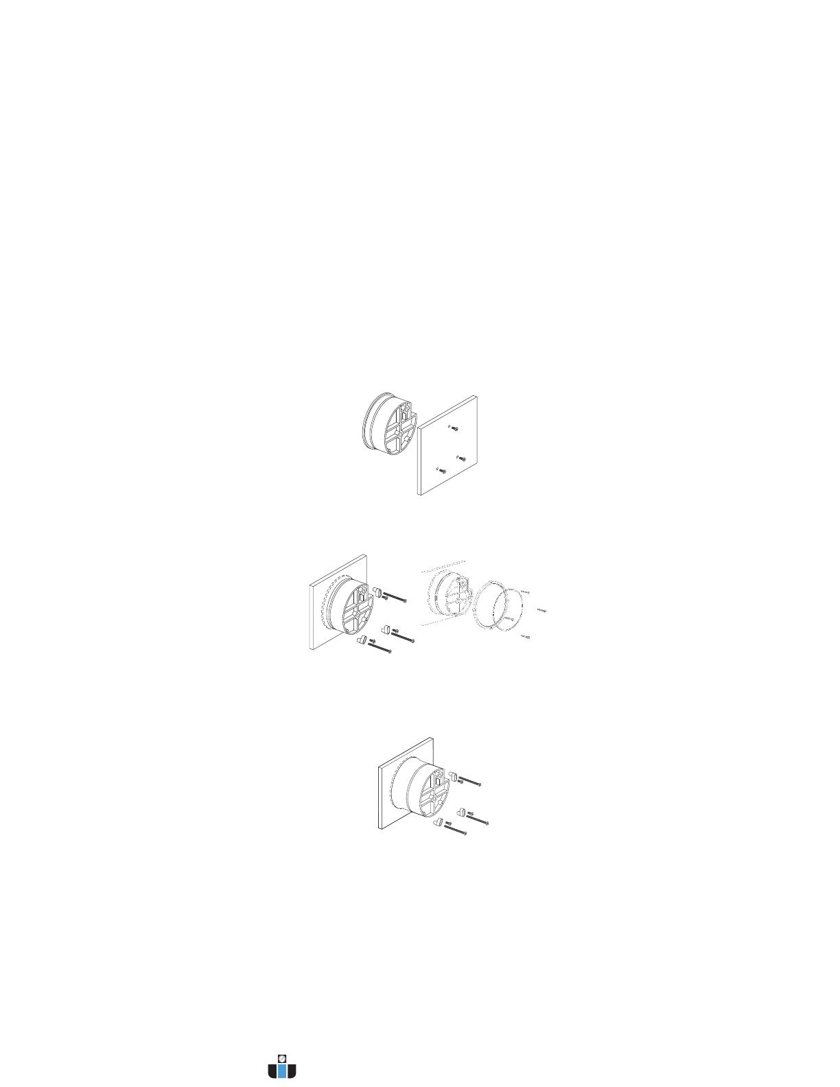
SURFACE MOUNTING
Locate mounting holes, 120° apart on a 4-1/8” dia. circle. Use
No. 6-32 machine screws of appropriate length.
FLUSH MOUNTING
Provide a 4-9/16” dia. (116 mm) opening in panel. Provide a 4-
3/4” dia. (120 mm) opening for MP and HP models. Insert gage
and secure in place with No. 6-32 machine screws of
appropriate length, with adapters, firmly secured in place.
FOR -SS BEzEL INSTALLATION
Provide a 4-9/16˝ opening in panel. Insert gage and secure with
supplied mounting hardware.
www.calcert.com [email protected]1.888.610.7664 0
5
10
15
20
25
30
  • Page 1 1
  • Page 2 2

Dwyer 2000 Series User manual

Type
User manual

The Dwyer 2000 Series Magnehelic® Differential Pressure Gage is a versatile device designed to measure and display pressure differences in air and non-combustible, compatible gases. With its durable construction and accurate readings, it is ideal for various applications, including HVAC systems, clean rooms, laboratories, and industrial settings. The gage boasts a 4-inch dial face for easy readability and comes equipped with duplicate high and low-pressure taps for versatile connection options. Its rugged housing and acrylic cover ensure protection against harsh environments.

Ask a question and I''ll find the answer in the document

Finding information in a document is now easier with AI