SCORPION Automotive Installation guide

Category
Car alarm
Type
Installation guide

SCORPION Automotive provides reliable protection for your vehicle. Its advanced technology offers features like ultrasonic volumetric protection to detect motion inside the vehicle, even if doors and windows are closed. Customizable settings allow you to tailor the system to your needs, including passive arming and a digital siren output. Whether you're seeking enhanced security or a convenient keyless entry system, SCORPION Automotive has you covered.

SCORPION Automotive provides reliable protection for your vehicle. Its advanced technology offers features like ultrasonic volumetric protection to detect motion inside the vehicle, even if doors and windows are closed. Customizable settings allow you to tailor the system to your needs, including passive arming and a digital siren output. Whether you're seeking enhanced security or a convenient keyless entry system, SCORPION Automotive has you covered.

INSTALLATION CERTIFICATE
The undersigned qualified installer attests to have personally fitted the here described vehicle
security system following the manufacturer instructions.
By:
Sold On: Type of Product:
S38
Vehicle:
Scorpion automotive permanently fitted aftermarket equipment must be installed by qualified
and authorised installers. Thatcham recommends to its insurer members that the installations
of certified products within the aftermarket are registered with an independent installation
registration system which can be accessed by insurance companies.
S38
INSTALLATION GUIDE
UK
Rev 0209/22
S-Series
A brand of the Scorpion Automotive Group
Scorpion House,
Drumhead Rd,
Chorley, Lancashire, UK,
PR6 7DE
INSTALLER MANUAL
2.1 – 20-PIN CONNECTOR
2.2 – 8-PIN CONNECTOR
PAGE02
1.0 – INTRODUCTORY NOTE…….…………………………………………………........PAGE 03
INSTALLER MANUAL
2.0 - PINOUT TABLES.................................................................................................... PAGE 06
2.1 - 20-way connector................................................................................................. PAGE 06
2.2 - 8-way connector................................................................................................... PAGE 06
3.0 - WIRING DIAGRAM…………................................................................................ PAGE 07
4.0 - TURN INDICATOR WIRING DIAGRAMS….......................................................... PAGE 08
4.1 - Standard connections........................................................................................... PAGE 08
4.2 - Connections for vehicles with separate lines......................................................... PAGE 08
4.3 - Connection to Hazard switch................................................................................. PAGE 08
5.0 - CENTRAL LOCKING CONNECTIONS TO ARM/DISARM THE SYSTEM.................
5.1 - Connections and management via CAN-BUS line............................................... PAGE 09
.
5.2 - Connections to locking motors............................................................................... PAGE 09
5.3 - Connections to turn indicators............................................................................... PAGE 09
5.4 - Combination connection........................................................................................ PAGE 09
6.0 - VEHICLE CODE PROGRAMMING…...................................................................... PAGE 09
7.0 - LEARNING OF TURN INDICATORS FLASHES..................................................... PAGE 10
8.0 - SYSTEM PROGRAMMING….................................................................................. PAGE 11
8.1 - Optical signals........................................................................................................ PAGE 12
8.2 - Acoustic signals..................................................................................................... PAGE 12
8.3 - Passive arming...................................................................................................... PAGE 12
8.4 – Digital siren output………………….................................................................. PAGE 12
8.5 – Door switch polarity selection................................................................................ PAGE 12
8.6 – Negative output selection for horn or additional siren ……………....................... PAGE
8.7 – Engine immobiliser passive arming.……………………………………………………...
9.0 - SYSTEM PROGRAMMING EXAMPLE.................................................................... PAGE 12
10.0 - ADDING NEW DEVICES....................................................................................... PAGE 13
11.0 - DELETING PROGRAMMED DEVICES................................................................. PAGE 14
12.0 - ULTRASONIC VOLUMETRIC PROTECTION........................................................ PAGE 14
12.1 – Connection and positioning ............................................................................... PAGE 15
12.2 – Sensor Adjustment .............................................................................................. PAGE 15
13.0 – SYSTEM RESET ………………………….................................................................
14.0 – WASTE ELECTRICAL AND ELECTRONIC EQUIPTMENT (WEEE) DIRECTIVE…...
15.0 – TECHNICAL SPECIFICATIONS……………………………………………………………
Dear customer, the S38 self-powered alarm system is supplied with 1 touch key to emergency
override the system and exclude the sensors and 2 RFID transponders (TAG cards) to
eng age/disengage the engine immobiliser. The alarm is compatible with wireless sensors.
Please read the present manual carefully to familiarize yourself fully with the alarm features and
operating procedures and do keep it handy for future reference. (See par. 2.0 PINOUT TABLES).
TABLE OF CONENTS
1.0
INTRODUCTORY NOTE
2.0
PINOUT TABLES
WHITE-ORANGE wire must ALWAYS be connected if system is to arm/disarm
via the turn indicators flashes.
PAGE 02
PAGE 03
PAGE 03
PAGE 03
PAGE 04
PAGE 05
PAGE 05
PAGE 05
PAGE 05
PAGE 06
PAGE 06
PAGE 06
PAGE 06
PAGE 06
PAGE 07
PAGE 08
PAGE 09
PAGE 09
PAGE 09
PAGE 09
PAGE 09
PAGE 09
PAGE 09
PAGE 09
PAGE 10
PAGE 11
PAGE 11
PAGE 12
PAGE 12
PAGE 12
PAGE 12
PAGE 13
PAGE 13
PAGE03
PAGE02PAGE03
4.1 – STANDARD CONNECTIONS
4.2 – CONNECTIONS FOR VEHICLES WITH SEPARATE LINES
4.3 – CONNECTION TO HAZARD SWITCH
3.0
WIRING DIAGRAM 4.0
TURN INDICATORS WIRING DIAGRAMS
PAGE04PAGE05
SYSTEM
S38
S38
S38
The alarm system can operate in various modes according to the vehicle on which it is installed
and the available connections (refer to the vehicle installation specifications).
It can be managed via the vehicle CAN BUS line and operate in combination with the turn indicator
flashes and/or the door locking motors. The system automatically manages the different
arming/disarming signals.
The various arming modes are listed below and the connections detailed in the following
paragraphs (refer to the vehicle specific installation instructions available in the restricted area of
our website: www.gemini-alarm.com).
Arming via CAN BUS line.
Arming via door lock motors.
Arming via turn indicator flashes.
Arming via turn indicator flashes and door lock motors.
Arming via turn indicator flashes, door lock motors and CAN BUS line.
5.1 - CONNECTIONS AND MANAGEMENT VIA CAN BUS LINE
System arming/disarming and alarms are managed via CAN therefore only connect the alarm CAN
wires to the vehicle CAN line.
5.2- CONNECTIONS TO LOCKING MOTORS
System arming/disarming connections must be made to the door lock motors (polarity reversal).
5.3- CONNECTIONS TO TURN INDICATORS
To arm/disarm the system, connect the WHITE-ORANGE wire to one of the turn indicators wires
and learn the lock/unlock flashes (par. 9.0).
5.4 – COMBINATION CONNECTION
This type of connection allows the system to operate via the CAN line in combination with the turn
indicators or the door lock motors or both.
The system will automatically manage the different lock/unlock signals according to the selected
configuration and connections.
If the system is to be managed via CAN BUS, it must be configured with the code set up for the
vehicle on which it is to be installed.
Here below is an example illustrating the configuration procedure where the code to be entered is
“1-0-3”.
Connect the harness connectors to the alarm.
Press and hold the button shown below until the LED lights up.
5.0
CENTRAL LOCKING CONNECTIONS TO ARM/DISARM THE SYSTEM
If the turn indicators lock/unlock flashes are identical, connect the door lock motors.
If the turn indicators flash when unlocking with the car mechanical key, do not make
this connection.
6.0
V
EHICLE CODE PROGRAMMING
A separate leaflet, included in the alarm packaging, lists available vehicles (codes are
updated at packaging time).
The system has an indicator LED that signals any wrong vehicle code inserted. The
code must range between 100 and 239 otherwise the LED on the unit blinks
repeatedly and the procedure is interrupted.
The previously inserted code remains stored.
The procedure is also invalidated if the LED blinks more than 10 times.
In this case there are no optical warnings, the procedure is simply interrupted.
In either case, repeat the entire procedure.
PAGE06PAGE07
When the last digit is entered, the alarm system “repeats” the entered code “1-0-3”.
Press the vehicle remote control lock/unlock buttons to make sure the alarm system works
properly.
If needed, disconnect the 8-pin connector and reconnect it after few seconds.
In order to arm/disarm via the turn indicators, the system must learn the vehicle lock (arm) and
unlock (disarm) flashes.
Connect the WHITE-ORANGE wire to the turn indicators and proceed as follows:
Disconnect the 8-pin harness connector from the unit.
Turn ignition key ON.
Re-connect the 8-pin harness connector to the unit; the LED turns ON steady.
Turn ignition key OFF, the LED will remain steady ON.
Close all doors and press the lock button on the original remote control.
When the turn indicators stop flashing, a Beep confirms the arming flashes have been learnt.
Press the unlock button on the original remote control.
When the turn indicators stop flashing, 2 Beeps confirm the disarming flashes have been learnt.
The system will automatically exit the procedure.
If the ignition key is turned OFF before the 60-sec. timeout, the 60-sec countdown restarts to allow
learning the turn indicators. It will timeout with a Bop.
If, after the ignition key is turned OFF, it is turned back ON, the procedure is interrupted with a Bop.
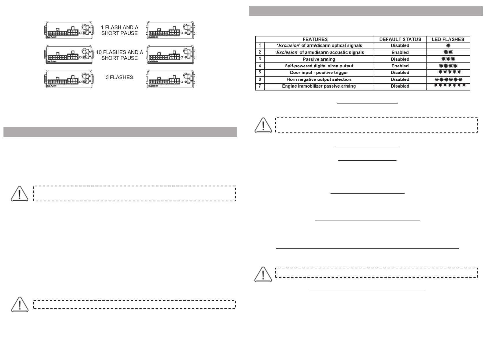
The table below applies to the system programmed in “standard configuration”.
Every time you enter the programming procedure, the alarm resets to the default settings.
8.1 – OPTICAL SIGNALS
Arming/disarming optical confirmation (Default setting => optical signals ON).
8.2 – ACOUSTIC SIGNALS
Arming/disarming acoustic confirmation (Default setting => acoustic signals OFF).
8.3 – PASSIVE ARMING
The system will automatically arm 60 sec. after ignition is switched OFF and the last door is
opened and closed.
Opening a door during the 60-sec. passive arming countdown will cause the procedure to interrupt;
it will resume once the door is closed.
8.4 – DIGITAL SIREN OUTPUT
If enabled, it allows communication between the alarm system and the digital siren (P/N 7725D).
If disabled, the output activates the additional siren (continuous or intermittent according to
configuration of feature n.6).
8.5 DOOR SWITCH POLARITY SELECTION
This feature modifies the alarm input signal (positive or negative trigger) according to the signal
generated by the door switch (Default setting => negative).
8.6 – NEGATIVE OUTPUT SELECTION FOR HORN OR ADDITIONAL SIREN
If feature n.4 is disabled, the output can be configured to select either the additional siren
(continuous tone) or the horn (intermittent tone). (Default setting => siren).
8.7 – ENGINE IMMOBILISER PASSIVE ARMING
If this feature is enabled, the engine block will automatically arm whenever the system is disarmed
and no TAG is detected for 30 sec.
If ignition key is cycled ON, the LED will flash quickly to warn you that the immobilizer is enabled.
7.0
LEARNING OF TURN INDICATORS FLASHES
At this point you have 60 sec. to turn ignition key OFF and carry out the learning
procedure otherwise it will timeout with a Bop.
8.0
SYSTEM PROGRAMMING
If the vehicle already has optical lock/unlock signals, the turn indicators alarm flashes
should be disabled.
PAGE08PAGE09
To cancel the programming of the turn indicators reset the system (par. 13.0).
Cannot be configured if feature n.4 has been programmed to enable the digital siren.
When modifying the programmable features, keep in mind that the ignition key is used to
disable the features while the touch key is used to enable them.
When ignition is cycled ON/OFF or the override key is touched to its receptacle, a Beep or Bop will
sound according to the action taken and the LED will flash according to the selected feature (table
8.0).
NB: The procedure must be carried out entirely.
Disarm the alarm system and make sure passive immobilizer is disabled.
Turn ignition key ON, the LED will power up for 2 sec. and, while the LED is ON, touch the override
key to its receptacle.
In both cases, the system moves on to the next feature.
Repeat the above steps to enable or disable the other features.
When the last feature is configured (either with the touch key or the ignition key), in addition to the
confirmation tone, 2 Bops and 1 Beep will sound and the turn indicators will flash twice
to confirm the end of the programming procedure.
9.0
SYSTEM PROGRAMMING EXAMPLE 10.0
ADDING NEW DEVICES
11.0
DELETING PROGRAMMED DEVICES
PAGE10PAGE11
The present device falls within the scope of the current WEEE Directive.
12.0
ULTRASONIC VOLUMETRIC PROTECTION
13.0
SYSTEM RESET
PAGE12PAGE13
14.0
WASTE ELECTRICAL AND ELECTRONIC EQUIPMENT
(
WEEE
)
DIRECTIVE
15.0
TECHNICAL SPECIFICATIONS
  • Page 1 1
  • Page 2 2
  • Page 3 3
  • Page 4 4
  • Page 5 5
  • Page 6 6
  • Page 7 7

SCORPION Automotive Installation guide

Category
Car alarm
Type
Installation guide

SCORPION Automotive provides reliable protection for your vehicle. Its advanced technology offers features like ultrasonic volumetric protection to detect motion inside the vehicle, even if doors and windows are closed. Customizable settings allow you to tailor the system to your needs, including passive arming and a digital siren output. Whether you're seeking enhanced security or a convenient keyless entry system, SCORPION Automotive has you covered.

Ask a question and I''ll find the answer in the document

Finding information in a document is now easier with AI