
1
SN280TYA
SL280TYA
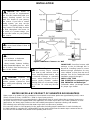
WARNING: If the information in this
manual is not followed exactly, a fire or
explosion may result in causing property
damage, personal injury, or loss of life.
WARNING: This is an unvented gas-fired
heater. It uses air (oxygen) from the room
in which it is installed. Provisions for
adequate combustion and ventilation air must
be provided. Refer to Air For Combus-
tion and Ventilation section on page 4 of this
manual.
WARNING: Improper installation,
adjustment, alteration, service or maintenance
can cause injury or property damage. Refer to
this manual for correct installation and opera-
tional procedures. For assistance or addi-
tional information consult a qualified installer,
service agency, or gas supplier.
This appliance may be installed in an aftermar-
ket* permanently located, manufactured
(mobile) home, where not prohibited by local
codes.
This appliance is only for use with the type of
gas indicated on the rating plate. This
appliance is not convertible for use with other
gases.
*Aftermarket: Completion for sale, not for purpose of
resale, from the manufacturer.
Table of Contents
Safety Information Warnings.....................................2
Air For Combustion & Ventilation............................4
Installation....................................................................6
Installing Logs.............................................................9
Operation Heater........................................................11
Specifications.............................................................13
Troubleshooting........................................................14
Parts Breakdown & Parts List..................................17
Log Placing Instructions..........................................21
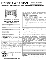
OWNER
’
S OPERATION AND INSTALLATION MANUAL
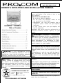
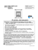
FREE STANDING LP.& NATURAL
GAS VENT-FREE STOVE
Do not store, or use gasoline or other flammable
vapors and liquids in the vicinity of this or any
other appliance.
WHAT TO DO IF YOU SMELL GAS
Do not try to light any appliance.
Do not touch any electrical switch; do not
use any phone in your building.
Immediately call your gas supplier from a
neighbor’s phone. Follow the gas supplier’s
instructions.
If you cannot reach your gas supplier, call
the fire department.
Installation and service must be performed by a
qualified installer, service agency or gas
supplier.
Installer : please leave these instructions with
the consumer
WATER VAPOR: A BY-PRODUCT OF UNVENTED ROOM
HEATERS
Water vapor is a by-product of gas combustion.An
unvented room heater produces approximately one
(1)ounce (30 ml) of water for every 1,000BTU’s
(.3KW’s) of gas input per hour, refer to page 6.
Consumer : please retain these instructions for
future use
CINTINENTAL APPLIANCE INC
5 Musick 4600 Highlands Parkway S.E.
Irvine Suite # D/E
CA 92618 Smyrna, GA 30080
TOLL-FREE NUMBER: 1-877-886-5989

2
IMPORTANT: Read this
owner’s manual carefully and
completely before trying to
assemble, operate, or service
this heater. Improper use of
this heater can cause serious
injury or death from burns,
fire, explosion, electrical
shock, and carbon monoxide
poisoning.
SAFETY INFORMATION WARNINGS
DANGER: Carbon monoxide
poisoning may lead to death!
Carbon Monoxide Poisoning:
Early signs of carbon monoxide
poisoning resemble the flu with
headaches, dizziness, or nausea.
If you have these signs, the heater
may not be working properly. Get
fresh air at once! Have heater
serviced. Some people are more
affected by carbon monoxide than
others. These include pregnant
women, people with heart or lung
disease or anemia, those under the
influence of alcohol, and those
at high altitudes.
Propane/LP Gas: Propane/LP gas
is odorless. An odor-making agent
is added to Propane/LP gas. The
odor helps you detect a Propane/LP
gas leak. However, the odor added
to Propane/LP gas can fade. Pro-
pane/LP gas may be present even
though no odor exists. Make certain
you read and understand all
warnings. Keep this manual for
reference. It is your guide to safe
and proper operation of this heater.
WARNING: Any change to
this fireplace or its controls can
be dangerous.
WARNING: Do not allow fans to
blow directly into the heater. Avoid any
drafts that alter burner flame patterns.
Ceiling fans can create drafts that alter
burner flame patterns. Altered burner
patterns can cause sooting.
Do not place clothing or other
flammable material on or near the
appliance. Never place any objects
in the fireplace.
Due to high temperatures, the
appliance should be located out of
traffic and away from furniture
and draperies.
WARNING: Do not use a blower
insert, heat exchanger insert, or other
accessory not approved for use with
this heater.
Heater becomes very hot when
running fireplace. Keep children and
adults away from hot surfaces to
avoid burns or clothing ignition.
Fireplace will remain hot for a time
after shutdown. Allow surfaces to
cool before touching.
Carefully supervise young children
when they are in the room with
fireplace.
You must operate this heater with
the heater screen in place. Make
sure heater screen is in place before
running heater.
Keep the appliance area clear and
free from combustible materials,
gasoline, and other flammable
vapors and liquids.
1. This appliance is only for use
with the type of gas indicated
on the rating plate. This
appliance is not convertible for
use with other gases.
2. Do not place propane/LP
supply tank(s) inside any
structure. Locate propane/LP
supply tank(s) outdoors.
3. If you smell gas:
Shut off gas supply.
Do not try to light any appliance.
Do not touch any electrical switch:
do not use any phone in your
building.
Immediately call your gas supplier
from a neighbor’s phone. Follow
the gas supplier’s instructions.
If you cannot reach your gas
supplier, call the fire department.
4. This heater shall not be installed
in a bedroom or bathroom.
5. Do not use this heater as a wood-
burning heater. Only use the logs
provided with the heater.
6. Do not add extra logs or ornaments
such as pine cones, vermiculite, or
rock wool.Using these added items
can cause sooting. Do not add lava
rock around base. Rock and debris
could fall into the control area of
heater. After servicing, always
replace screen before operating
heater.
7. You must operate this heater with
the heater screen in place. Make
sure heater screen is in place
before running heater.
8. This heater is designed to be
smokeless. If logs ever appear to
smoke, turn off heater and call a
qualified service person. Note:
During initial operation, slight
smoking could occur due to log
curing and heater burning
manufacturing residues.
9. To prevent the creation of soot,
follow the instructions in Cleaning
and Maintenance, page 12.
10.Before using furniture polish, wax,
carpet cleaner, or similar products,
turn heater off. If heated, the
vapors from these products may
create a white powder residue
within burner box or on adjacent
walls or furniture.
11.This heater needs fresh air
ventilation to run properly. This
heater has an Oxygen Depletion
Sensing (ODS) safety shutoff
system. The ODS shuts down the
heater if not enough fresh air is
available. See Air for Combustion
and Ventilation, pages 4 through 6.
If heater keeps shutting off, see
Troubleshooting, pages 14
through 16.
12. Do not run heater:
Where flammable liquids or vapors
are used or stored.
Under dusty conditions.
13.Do not use this heater to cook
food or burn paper or other objects.
14. Do not use heater if any part has
been under water. lmmediately call
a qualified service technician to
inspect the room heater and to
replace any part of the control
system, and any gas control,
which has been under water.

3
SAFETY INFORMATION
Continued
15. Turn off heater and let it cool before
servicing. Only a qualified service
person should service and repair
heater.
16. Operating heater above elevations
of 4,500 feet could cause pilot
outage.
17. Do not operate heater if any log is
broken. Do not operate heater if a
log is chipped (dime-sized or larger).
18. To prevent performance problems,
do not use propane/LP fuel tank: of
less than 100lbs. capacity.
LOCAL CODES
lnstall and use heater with care.
Follow all local codes. In the
absence of local codes, use the
latest edition of The National Fuel
Gas Code. ANSZ223.1, also known
as NFPA54*.
*Available from:
American National Standards
lnstitute, lnc.
1430 Broadway
New York. NY10018
National Fire Protection
Association, lnc.
Batterymarch Park
Quincy. MA 02269
This heater is designed for vent-free
operation. State and local codes in
some areas prohibit the use of
vent-free heaters.
UNPACKING
1. Remove top inner pack.
2. Tilt carton so that stove is upright.
3. Remove protective side packaging.
4. Slide stove out of carton.
5. Remove protective plastic wrap.
6. Remove screen by lifting and then
pulling forward.
7. Remove log set by cutting plastic
ties.
8. Carefully unwrap log.
9. Check for any shipping damage. If
stove or log is damaged, promptly
inform dealer where you bought
stove.
PRODUCT FEATURES
SAFETY PILOT
This heater has a pilot with an
Oxygen Depletion Sensing (ODS)
safety shutoff system. The ODS/pilot
is a required feature for vent-free
room heaters. The ODS/pilot shuts off
the heater if there is not enough
fresh air.
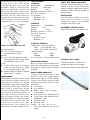
PIEZO IGNITION SYSTEM
This heater has a piezo ignitor.
This system requires no matches,
batteries, or other sources to light
heater.
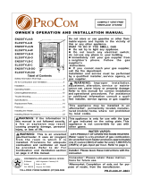
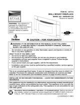
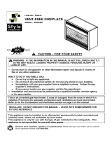
PRODUCT IDENTIFICATION
Figure1-Vent-Free Propane/LP Gas Freestanding Pedestal Stove

4
AIR FOR COMBUSTION AND VENTILATION
WARNING: This heater shall not
be installed in a confined space or
unusually tight construction unless
provisions are provided for adequate
combustion and ventilation air. Read
the following instructions to insure
proper fresh air for this and other
fuel-burning appliances in your home.
PROVIDING ADEQUATE
VENTILATION
The following are excerpts from
National Fuel Gas Code, NFPA54/
ANSZ223.1.Section 5.3, Air for
Combustion and Ventilation.
All spaces in homes fall into one of
the three following ventilation
classifications:
1. Unusually Tight Construction
2. Unconfined Space
3. Confined Space
The information on pages 4 through 6
will help you classify your space and
provide adequate ventilation.
Confined and Unconfined Space
The National Fuel Gas Code, ANS
Z223.1 defines a confined space as a
space whose volume is less than 50
cubic feet per 1,000 Btu per hour
(4.8 m
3
per kw) of the aggregate
input rating of all appliances installed
in that space and an unconfining space
as a space whose volume is not less
than 50 cubic feet per 1,000 Btu per
hour (4.8 m
3
per kw) of the aggregate
input rating of all appliances installed
in that space. Rooms communicating
directly with the space, in which the
appliances are installed*, and through
openings not furnished with doors,
are considered a part of the uncon-
fined space.
This heater shall not be installed in
a confined space or unusually tight
construction unless provisions are
provided for adequate combustion
and ventilation air.
* Adjoining rooms are communicating
only if there are doorless passage-
ways or ventilation grills between
them.
Unusually Tight Construction
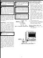
DETERMINING FRESH-AIR FLOW FOR HEATER LOCATION
Determining if You Have a Confined or Unconfined Space
Use this worksheet to determine if you have a confined or unconfined space.
Space: Includes the room in which you will install heater plus any adjoining rooms with doorless passageways
or ventilation grills between the rooms.
1. Determine the volume of the space (length
×
width
×
height).
Length
×
Width
×
Height= cu.ft. (volume of space)
Example: Space size 20ft. (length)
×
16ft( width)
×
8ft. (ceiling height)=2560cu. ft. (volume of space)
If additional ventilation to adjoining room is supplied with grills or openings, add the volume of these
rooms to the total volume of the space.
2. Divide the space volume by 50 cubic feet to determine the maximum Btu/Hr the space can support.
(volume of space)÷50 cu. ft.=(Maximum Btu/Hr the space can support)
Example: 2560 cu. ft. (volume of space)
÷50 cu.ft.=51.2 or 51,200(maximum Btu/Hr the space can support)
AIR FOR COMBUSTION AND VENTILATION
Continued
The air that leaks around doors and
windows may provide enough fresh
air for combustion and ventilation.
However, in buildings of unusually
tight construction you must provide
additional fresh air.
Unusually tight construction is defined
as construction where:
a) walls and ceilings exposed to the
outside atmosphere have a
continuous water vapor retarder
with a rating of one perm ( 6
×10
-11
kg per pa-sec-m
2
) or less with
openings gasketed or sealed
and
b) weather stripping has been added
on openable windows and doors
and
c) caulking or sealants are applied to
areas such as joints around win-
dow and door frames, between
sole plates and floors, between
wall-ceiling joints, between wall
panels, at penetrations for
plumbing, electrical, and gas lines,
and at other openings.
If your home meets all of the three
criteria above, you must provide
additional fresh air. See Ventilation Air
From Outdoors, page 5.
If your home does not meet all of the
three criteria above, proceed to
Determining Fresh-Air Flow For Heater
Location, below.

5
WARNING: Rework worksheet, adding the space of the adjoining unconfined space. The combined
spaces must have enough fresh air to supply all appliances in both spaces.
If the actual Btu/Hr used is less than the maximum Btu/Hr the space can support, the space is an
unconfined space. You will need no additional fresh air ventilation.
3. Add the Btu/Hr of all fuel burning appliances in the space.
Vent-free heater
Btu/Hr
Gas water heater*
Btu/Hr
Gas furnace
Btu/Hr
Vented gas heater
Btu/Hr
Gas heater logs
Btu/Hr
Other gas appliances* +
Btu/Hr
Total =
Btu/Hr
*Do not include direct-vent gas appliances. Direct-vent draws combustion air from the outdoors and
vents to the outdoors.
4. Compare the maximum Btu/Hr the space can support with the actual amount of Btu/Hr used.
Btu/Hr (maximum the space can support)
Btu/Hr (actual amount of Btu/Hr used)
Example : 51,200 Btu/Hr(maximum the space can support)
56,000 Btu/Hr(actual amount of Btu/Hr used)
The space in the above example is a confined space because the actual Btu/Hr used is more than the
maximum Btu/Hr the space can support.
You must provide additional fresh air. Your options are as follows:
A. Rework worksheet, adding the space of an adjoining room. If the extra space provides an unconfined
space, remove door to adjoining room or add ventilation grills between rooms. See Ventilation Air From
Inside Building, below.
B. Vent room directly to the outdoors. See Ventilation Air From Outdoors, below .
C. Install a lower Btu/Hr heater, if lower Btu/Hr size makes room unconfined.
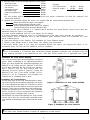
Figure 2 -Ventilation Air from Inside Building
Example:
Gas water heater 30,000 Btu/Hr
Vent-free heater
+ 26,000 Btu/Hr
Total = 56,000 Btu/Hr
WARNING: If the area in which the heater may be operated is smaller than that defined as an unconfined
space or if the building is of unusually tight construction, provide adequate combustion and ventilation air by one
of the methods described in the National Fuel Gas Code, ANS Z223.1, Section 5.3 or applicable local codes.
This fresh air would come from an adjoining unconfined
space. When ventilating to an adjoining unconfined
space, you must provide two permanent openings: one
within 12
" of the ceiling and one within 12" of the floor
on the wall connecting the two spaces (see options 1
and 2, Figure 2). You can also remove door into
adjoining room (see option 3, Figure 2). Follow the
National Fuel Gas Code. NFPA 54/ANS Z223.1.
Section 5.3, Air for Combustion and Ventilation for
required size of ventilation grills or ducts.
Ventilation Air From lnside Building
Ventilation Air From Outdoors
Provide extra fresh air by using ventilation grills or ducts.
You must provide two permanent openings: one within
12
" of the ceiling and one within 12" of the floor. Connect
these items directly to the outdoors or spaces open to the
outdoors. These spaces include attics and crawl spaces.
Follow the National Fuel Gas Code, NFPA 54/ANS
Z223.1, Section 5.3. Air for Combustion and Ventilation
for required size of ventilation grills or ducts.
IMPORTANT: Do not provide openings for inlet or outlet
air into attic if attic has a thermostat-controlled power
vent. Heated air entering the attic will activate the power
vent.
Figure 3 -Ventilation Air from Outdoors

6
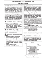
NOTICE: This heater is
intended for use as supplemental
heat. Use this heater along with your
primary heating system. Do not
install this heater as your primary
heat source. If you have a central
heating system, you may run the
system's circulating blower while
using heater. This will help circulate
the heat throughout the house . In
the event of a power outage, you
can use this heater as your primary
heat source.
INSTALLATION
WARNING: A qualified service
person must install heater. Follow all
local codes.
WARNING: Never install the
heater
in a bedroom or bathroom
in a recreational vehicle
where curtains, furniture, clothing,
or other flammable objects are less
than 42 inches from the front, top, or
sides of the heater.
WARNING: Maintain the
minimum clearances. If you can,
provide greater clearances from
floor, ceiling, and adjoining side and
back walls.
CAUTION: This heater creates
warm air currents. These currents
move heat to wall surfaces next to
heater. Installing heater next to vinyl
or cloth wall coverings or operating
heater where impurities (such as
tobacco smoke, aromatic candles,
cleaning fluids, oil or kerosene lamps,
etc.) in the air exist may discolor
walls.
IMPORTANT: Vent-free heaters add
moisture to the air. Although this is
beneficial, installing heater in rooms
without enough ventilation air may
cause mildew to form from too much
moisture. See Air for Combustion and
Ventilation, pages 4 through 5.
CHECK GAS TYPE
FOR SL280TYA use propane/LP gas
FOR SN280TYA use Natural gas.
Call dealer where you bought heater
for proper type heater.
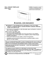
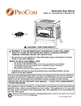
Figure 4 -Minimum Clearance to Wall
WATER VAPOR:A BY-PRODUCT OF UNVENTED ROOM HEATERS
Water vapor: a by-product of gas combustion.An unvented room heater productes approximately one(1) ounce
(30ml) of water for every 1,000BTU’s (.3KW’s) of gas input per hour.
Unvented room heaters are recommended as supplemental heat (a room) rather than a primary heat source
(an entire house),in most supplemental heat appllcation, the water vapor does not create a problem, in most
applications, the water vapor enhances the low humidity atmosphere experience during cold weather.
The following steps will help insure that water vapor does not become a problem,
1.Be sure the heater is sized properly for the application,including ample combusion air and circulation air.
2.If high humidity is experienced, a dehumldifier may be used to help lower the water vapor content of the air.
3.Do not use an unvented room,heater as the primary heat source.
Ceiling

7
CLEARANCES TO
COMBUSTIBLES
(Vent-Free Operation Only)
Carefully follow the instructions below.
This stove is a freestanding unit
designed to set directly on the floor.
IMPORTANT: You must maintain
minimum wall and ceiling clearances
during installation. The minimum
clearances are shown in Figure 4.
Measure from outermost point of stove
top.
Minimum Wall and Ceiling
Clearances
(see Figure 4)
A. Clearances from outermost point
of stove top to any combustible side
wall should not be less than 12
inches.
B. Clearances from outermost point of
stove top to any combustible back
wall should not be less than 6
inches (lncludes corner
installations).
C. Clearances from the stove top to
the ceiling should not be less than
48 inches.
CONNECTING TO GAS
SUPPLY
WARNING: A qualified service
person must connect heater to gas
supply. Follow all local codes.
CAUTION: Never connect
heater directly to the propane/LP
supply. This heater requires an
external regulator (not supplied).
lnstall the external regulator between
the heater and propane/LP supply.
INSTALLATION ITEMS
NEEDED
Before installing heater, make sure
you have the items listed below.
piping (check local codes)
sealant (resistant to propane/LP gas)
equipment shutoff valve*
test gauge connection*
sediment trap
see joint
pipe wrench
flexible gas hose.(check local codes)
A CSA design-certified equipment
shutoff valve with 1/8
" NPT tap is
an acceptable alternative to test
gauge connection. Purchase the
optional CSA design-certified
equipment shutoff valve from your
dealer. See Accessories.
Figure 5 -Gas Regulator Location
and Gas Line Access Into Stove
Cabinet
Figure 6 -External Regulator With
Vent Pointing Down
Figure 7 -Gas Connection
FOR LP models
The installer must supply an external
regulator. The external regulator will
reduce incoming gas pressure. You
must reduce incoming gas pressure
to between 11 to 14
" inches of water.
If you do not reduce incoming gas
pressure, heater regulator damage
could occur. lnstall external regulator
with the vent pointing down as shown
in Figure 6. Pointing the vent down
protects it from freezing rain or sleet.
* Purchase the optional CSA design-certified equipment shutoff valve from
your dealer. See Accessories, page 13.
* Minimum inlet pressure for purpose of input adjustment.
Propane/LP
Supply Tank
FOR NG models:
(4” W.C.-10.5”W.C.)
No External Regulator Needed
purchase
NG MODELS:
5” to 10.5” W.C.
Gas supplier provides external
regulator for natural gas.

8
WARNING: Never connect
heater to private (non-utility) gas
wells. This gas is commonly known
as wellhead gas.
CAUTION: Use only new, black
iron or steel pipe. Internally-tinned
copper tubing may be used in
certain areas. Check your local
codes. Use pipe of 1/2
" diameter or
greater to allow proper gas volume
to heater. If pipe is too small, loss
of pressure will occur.
Installation must include an equip-
ment shutoff valve, union, and plugged
1/8
" NPT tap. Locate NPT tap within
reach for test gauge hook up. NPT
tap must be upstream from heater
(see Figure 7).
IMPORTANT: Install equipment
shutoff valve in an accessible
location. The equipment shutoff
valve is for turning on or shutting
off the gas to the appliance. Apply
pipe joint sealant lightly to male
threads.This will prevent excess
sealant from going into pipe. Excess
sealant in pipe could result in clogged
heater valves.
CAUTION: Use pipe joint seal-
ant that is resistant to liquid
petroleum(LP) gas.
We recommend that you install a
sediment trap in supply line as shown
in Figure 7. Locate sediment trap
where it is within reach for cleaning.
Install in piping system between fuel
supply and heater. Locate sediment
trap where trapped matter is not likely
to freeze. A sediment trap traps
moisture and contaminants. This keeps
them from going into heater controls.
If sediment trap is not installed or is
installed wrong, heater may not run
properly.
CAUTION: To avoid damage to
regulator, hold gas regulator with a
wrench when connecting into gas
piping and/or fittings.
WARNING: Never use an
open flame to check for a leak.
Apply a mixture of liquid soap and
water to all joints. Bubbles forming
show a leak. Correct all leaks at
once.
CAUTION: Make sure external
regulator has been installed between
propane/LP supply and heater. See
guidelines under Connecting to Gas
Supply, page 7.
Figure 8 -Equipment Shutoff Valve
Pressure Testing Gas Supply
Piping System Test Pressures In
Excess Of 1/2 PSIG(3.5kPa)
1. Disconnect heater with its
appliance main gas valve (control
valve) and equipment shutoff valve
from gas supply piping system.
Pressures in excess of 1/2 psig
will damage heater regulator.
2. Cap off open end of gas pipe
where equipment shutoff valve
was connected.
3. Pressurize supply piping system
by either using compressed air or
opening propane/LP supply valve.
4. Check all joints of gas supply
piping system. Apply mixture of
liquid soap and water to gas
joints. Bubbles forming show a
leak.
5. Correct all leaks at once.
6. Reconnect heater and equipment
shutoff valve to gas supply. Check
reconnected fittings for leaks.
Pressure Testing Heater Gas
Connections
1. Open equipment shutoff valve
(see Figure 8).
Figure 9.1 -Checking Gas Joints

9
2. Open natural supply tank valve.
3. Make sure control knob of heater is
in the OFF position.
4. Check all joints from equipment
shutoff valve to control valve
(SL280TYA see Figure 9.1
SN280TYA see Figure 9.2).
Apply mixture of liquid soap and
water to gas joints. Bubbles
forming show a leak.
5. Correct all leaks at once.
6. Light heater (see Operating
Heater).Check all other internal
joints for leaks.
7. Turn off heater (see To Turn Off
Gas to Appliance).
WARNING: Failure to position
the parts in accordance with these
diagrams or failure to use only parts
specifically approved with this heater
may result in property damage or
personal injury.
CAUTION: After installation
and periodically thereafter, check to
ensure that no flame comes in
contact with any log. With the heater
set to HIGH, check to see if flames
contact any log. If so, reposition logs
according to the log installation
instructions in this manual. Flames
contacting logs will create soot.
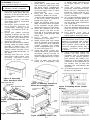
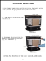
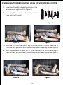
INSTALLING LOGS
It is very important to install the logs
exactly as instructed. Do not modify
logs. Only use logs supplied with
heater.
Place log set on grate to fit as illus-
trated in Figure 10.
Make sure log sits flat on firebox
floor (see Figure 10).
IMPORTANT: Make sure log does
not cover any burner ports (see
Figure11).
Also see placing instruction pgs.
21.
Figure 10 -Installing Log Set
Figure 11 -Installing Log Set (Top View)
Figure 9.2 -Checking Gas Joints
Natural
Gas Meter
Log set
Firebox Floor

10
ACCESSORY PF06-YJLF-F
Tools required: Phillips screwdriver
1. From back of heater remove the
Knock-out center panel with two
brackets at the four sides with a
phillips head screwdriver (see
Figure12).
2. Disconnect power cord wires
from blower motor (if connected)
(see Figure 13).
3. Disconnect green ground wire
from blower housing (if
connected)by removing screw
holding wire terminal (see Fig-
ure 13).
4. Install one rubber bushing
provided in blower kit into the
1.5
" hole in the left rear of firebox
floor. Access hole through the
rectangular opening in the rear
panel (see Figure 14).
5. Attach the two brackets to blower
housing using four white screws
provided in blower kit ( 2 for
each bracket) (see Figure 15).
Tighten screws securely. Place
blower assembly temporarily on
top panel.
6. Working from the rear of the
stove place entire power cord,
including operation control
housing, in lower control
Figure 12 -Removing
Stove Knock-out Panel
compartment.
7. Route ends of 4-wire power cord
and thermostat switch up from
the lower control compartment
through the rubber bushing, then
up to the upper cavity of stove
(see Figure 16).
8. Using one big black screw
provided in blower kit, mount
bracket with thermostat switch
to the left of firebox on back of
heater (see figure 16).
9. Attach the terminal ends of the
white and black power cord wires
to the terminals on the blower
motor (see Figure 13). Push firmly.
10. Attach the terminal end of the
green power cord wire to the
front tab of the blower housing
using black screw provided (see
Figure 13).
11. Place blower assembly
temporarily on top panel.
12. Install control knob onto output
shaft of operation control housing
(see figure 16). Place operation
control housing just inside
control compartment door in front
of stove (see Figure 17).
13. Using two black screws pro-
vided in blower kit, mount blower
operation control housing to
mounting tab in left side of lower
control compartment (see Figure
17).
14. Check to make sure that the
power cord is completely clear
of blower wheel and there are
no foreign objects in blower
wheel.
15. Using the screws removed
previously, mount blower assem-
bly to stove by reattaching the
Knock-out center panel to rear
panel (see Figure 15). Tighten
screws securely.
16 Use screws provided in blower kit
to assemble the plate which as-
sembled with strain relief bush-
ing and power cord on the knock-
out center panel.
17. Peel off the backing paper and
stick the supplied wiring diagram
decal on the stove floor as shown
in Figure 16.
18. Plug power cord into a
convenient 3-prong grounded
wall receptacle near the stove.
19. Using Auto/O/Man switch, turn
blower on and check for
operation. Turn on Auto/O/Man
switch to the desired position.
Man position will remain con-
stantly on. Auto position will be
controlled by the thermostat on
fan blower unit. To stop the
operation turn unit switch to the
O position.
20. All remaining parts from blower
kit may be discarded.
WARNING: ELECTRICAL
GROUNDINGINSTRUCTIONS This
appliance is equipped with a three-
prong (grounding) plug for your pro-
tection against shock hazard and
should be plugged directly into a
properly grounded three-prong
receptacle.
NOTICE: Shut off gas heater during
the following blower installation.
Figure 13 -Removing Wires From
Blower
Figure 15 -Attaching brackets to
blower and mounting blower
Figure 14 -Installing Bushing
Figure 17-Installing Blower Control
Housing
Figure 16 -Routing Power Cord

11
OPERATING HEATER
FOR YOUR SAFETY
READ BEFORE LIGHTING
WARNING: If you do not
follow these instructions exactly, a
fire or explosion may result causing
property damage, personal injury or
loss of life.
A. This appliance has a pilot which
must be lighted by hand. When
lighting the pilot, follow these
instructions exactly.
B. BEFORE LIGHTING smell all
around the appliance area for
gas. Be sure to smell next to the
floor because some gases are
heavier than air and will settle
on the floor.
WHAT TO DO IF YOU SMELL GAS
Do not try to light any appliance.
Do not touch any electrical
switch; do not use any phone in
your building.
Immediately call your gas
supplier from a neighbor's
phone. Follow the gas supplier's
instructions.
If you cannot reach your gas
supplier, call the fire department.
C. Use only your hand to push in or
turn the gas control knob. Never
use tools. If the knob will not push
in or turn by hand, don't try to
repair it. Call a qualified service
technician or gas supplier. Force
or attempted repair may result
in a fire or explosion.
D. Do not use this appliance if any
part has been under water.
Immediately call a qualified
service technician to inspect the
appliance and to replace any
part of the control system,
and any gas control, which has
been under water.
1. STOP! Read the safety
information.
2. Make sure equipment shutoff
valve is fully open.
3. Turn control knob clockwise
to the OFF position.
4. Wait five (5) minutes to clear out
any gas. Then smell for gas,
including near the floor. If you
smell gas, STOP! Follow "B" in
the safety information. If you
don't smell gas, go to the
next step.
5. Turn control knob counterclock-
wise
to the PILOT position.
Press in control knob for five (5)
seconds (see Figure 18).
Note: You may be running this
heater for the first time after
hooking up to gas supply. If so,
the control knob may need to
be pressed in for 30 seconds
or less. This will allow air to
bleed from the gas system.
6. With control knob pressed in,
press and release ignitor button.
This will light pilot. The pilot is
attached to the front burner. If
needed, keep pressing ignitor
button until pilot lights.
Note: If pilot does not stay lit,
contact a qualified service
person or gas supplier for
repairs. Until repairs are made,
light pilot with match. To light
pilot with match, see Manual
Lighting Procedure (page 13).
7. Keep control knob pressed in for
LIGHTING
INSTRUCTION
NOTICE: During initial operation of
new heater, burning logs will give
off a paper-burning smell. Orange
flame will also be present. Open a
window to vent smell. This will only
last a few hours.
30 seconds after lighting pilot.
After 30 seconds. release
control knob.
If control knob does not pop
out when released, contact a
qualified service person or gas
supplier for repairs.
Note: If pilot goes out, repeat
steps 3 through 7. This heater
has a safety interlock system.
Wait one (1) minute for system
to reset before lighting pilot again.
8. Turn control knob counter-
clockwise
to desired heating
level. The burners should light.
Set control knob to any heat level
between HI and LO.
TO TURN OFF GAS
TO APPLIANCE
Shutting Off Heater
Turn control knob clockwise
to
the OFF position.
Shutting Off Burners Only (Pilot
stays lit)
Turn control knob clockwise
to
the PILOT position.
Figure 18 -Control Knob and
Ignitor Button Location
Figure 19 -Pilot
CAUTION: Do not try to adjust
heating levels by using the
equipment shutoff valve.

12
THERMOSTAT CONTROL
OPERATION SN280TYA/SL280TYA The
thermostat control knob can be set to
any comfort level between HI and LO.
The thermostat will gradually modu-
late the heat output and flame height
from higher to lower settings, or pilot
in order to maintain the comfort level
you select. The ideal comfort setting
will vary by household depending upon
the amount of space to be heated,
the output of the central heating
system, etc.
Note: Selecting the Hi setting with
the control knob will cause the
burners to remain fully on, without
modulating down in most cases.
MANUAL LIGHTING
PROCEDURE
1. Follow steps 1 through 5 under
Lighting Instructions.
2. Depress control knob and light
pilot with match.
3. Keep control knob pressed in
for 30 seconds after lighting
pilot. After 30 seconds, release
control knob. Now follow step
8 in column 2.
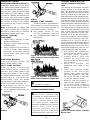
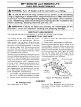
INSPECTING BURNERS
Check pilot flame pattern and
burner flame patterns often.
PILOT FLAME PATTERN
Figure 20 shows a correct pilot
flame pattern. Figure 21 shows an
incorrect pilot flame pattern. The
incorrect pilot flame is not touching
the thermocouple.This will cause the
thermocouple to cool. When the
thermocouple cools, the heater
will shut down. If pilot flame pattern is
incorrect, as shown in Figure 21:
turn heater off (see To Turn
Off Gas to Appliance, page 11)
see Troubleshooting, pages 14
through 16
Figure 20 -Correct Pilot Flame
Pattern
Figure 22 shows a correct burner
flame pattern. Figure 23 shows an
incorrect burner flame pattern. If
burner flame pattern is incorrect:
turn heater off (see To Turn
Off Gas to Appliance, page 11)
see Troubleshooting, pages 14
through 16
CLEANING AND MAINTENANCE
Figure 21 -Incorrect Pilot Flame
Pattern
BURNER FLAME PATTERN
Figure 22 -Correct Flame Pattern
with Control Knob Set to High Flame
Figure 23 -Incorrect Flame Pattern
with Control Knob Set to High Flame
WARNING: Turn off heater and
let cool before cleaning.
CLEANING BURNER INJECTOR
HOLDER AND PILOT AIR INLET
HOLE
The primary air inlet holes allow the
proper amount of air to mix with the
gas. This provides a clean burning
flame. Keep these holes clear of dust,
dirt, lint, and pet hair. Clean these air
inlet holes prior to each heating season.
Blocked air holes will create soot. We
recommend that you clean the unit
every three months during operation
and have heater inspected yearly by a
qualified service person. We also
recommend that you keep the burner
tube and pilot assembly clean and
free of dust and dirt. To clean these
parts we recommend using com-
pressed air no greater than 30 PSI.
Your local computer store, hardware
store, or home center may carry com-
pressed air in a can. You can use a
vacuum cleaner in the blow position. If
using compressed air in a can, please
follow the directions on the can. If you
don't follow directions on the can, you
could damage the pilot assembly.
1. Shut off the unit, including the
pilot. Allow the unit to cool for
at least thirty minutes.
2. Inspect burner, pilot and
primary air inlet holes on
injector holder for dust and dirt
(see figure 24).
3. Blow air through the
ports/slots and holes in the
burner.
4. Check the injector holder
located at the end of the
burner tube again. Remove
any large particles of dust, dirt,
lint, or pet hair with a soft cloth
or vacuum cleaner nozzle.
5. Blow air into the primary air
holes on the injector holder.
6. In case any large clumps of
dust have now been pushed
into the burner repeat steps 3
and 4.
CAUTION: You must keep
control areas, burner, and
circulating air passageways of
heater clean. Inspect these
areas of heater before each
use. Have heater inspected
yearly by a qualified service person.
Heater may need more
frequent cleaning due to
excessive lint from carpeting,
bedding material, pet hair, etc.
Figure 24 -Injector Holder on Outlet
Burner Tube

13
Clean the pilot assembly also. A
yellow tip on the pilot flame
indicates dust and dirt in the pilot
assembly. There is a small pilot air
inlet hole about two inches from
where the pilot flame comes out of
the pilot assembly (see Figure 25).
With the unit off, lightly blow air
through the air inlet hole. You may
blow through a drinking straw if
compressed air is not available.
Air Passageways
Use a vacuum cleaner or
pressurized air to clean.
Exterior
Use a soft cloth dampened with a
mild soap and water mixture. Wipe
the cabinet to remove dust.
LOGS
If you remove logs for cleaning,
refer to Installing Logs, page
9, to properly replace logs.
Replace log(s) if broken or chipped
(dime-sized or larger).
MAIN BURNER
Periodically inspect all burner flame
holes with the heater running. All
slotted burner flame holes should
be open with yellow flame present. All
round burner flame holes should be
open with a small blue flame
present. Some burner flame holes
may become blocked by debris or
rust, with no flame present. If so,
turn off heater and let cool. Either
remove blockage or replace burner.
Blocked burner flame holes will
create soot. Review your video
included with your heater for
additional cleaning instructions.
Figure 25 -Pilot Inlet Air Hole
SPECIFICATIONS
SL280TYA
Btu(Variable) 20000/28000
Gas Type Propane/LP
Ignition Piezo
Manifold Pressure 8.0"W.C.
Inlet Gas Pressure
(In. of water)*
Maximum 14"
Minimum 11"
SN280TYA
Btu(Variable) 20000/28000
Gas Type NG
Ignition Piezo
Manifold Pressure 3.0"W.C.
Inlet Gas Pressure
(In. of water)*
Maximum 10.5"
Minimum 5"
SL280TYA SN280TYA
Dimensions, Inches (H
×
W
×
D)
Stove 27 1/2"
×
28"
×
17 1/2"
Carton 21 3/4"
×
30 1/4"
×
31 1/2"
Weight, pounds
Stove 99lbs.
Shipping 116lbs.
*For purposes of input adjustment
REPLACEMENT PARTS
Note: Use only original replacement
parts. This will protect your warranty
coverage for parts replaced under
warranty.
PARTS UNDER WARRANTY
Contact authorized dealers of this
product. If they can't supply original
replacement part(s), call the number
on the front of this manual. When
contacting your dealer or PRO-COM,
have ready:
Your name
Your address
Model and serial numbers
of your heater
How heater was malfunctioning
Type of gas used (Natual Gas or
propane/LP gas)
Purchase date
Warranty card.
Usually, we will ask you to
return the defective part to the
factory.
PARTS NOT UNDER WARRANTY
Contact authorized dealers of this
product or Parts Central. If they can’t
supply original replacement part(s)
call PRO-COM’s toll-free number on
the front page.
ACCESSORIES
Purchase these heater accessories
from your local dealer or Parts
Central. This part is not currently
available from PRO-COM.
EQUIPMENT SHUTOFF VALVE -
Equipment shutoff valve with 1/8" NPT tap.
Burner
FLEX IBLE GAS HOSE
Flexible gas hose is used for con-
necting the heater to gas supply.
the flex hose must be CSA Approved.

14
TROUBLESHOOTING
Note: All troubleshooting
items are listed in order of
operation.
WARNING: Only a
qualified service person
should service and repair
heater.
CAUTION: Never use a wire,
needle, or similar object to
clean ODS/pilot. This can
damage ODS/pilot unit.
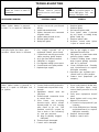
REMEDY
1. Replace ignitor.
2. Replace ignitor.
3. Reconnect ignitor cable.
4. Free ignitor cable if pinched
by any metal or tubing. Keep
ignitor cable dry.
5. Replace ignitor cable.
6. Replace control valve ( piezo
is part of control valve).
1. Turn on gas supply or open
equipment shutoff valve.
2. Fully press in control knob while
pressing ignitor button.
3. Continue holding down control
knob. Repeat igniting operation
until air is removed.
4. Clean ODS/pilot (see Cleaning
and Maintenance) or replace
ODS/pilot assembly.
5. Reposition gas regulator turn
control knob to pilot position.
6. Contact local propane/LP gas
company.
1. Press control knob in all the way.
2. After ODS/pilot lights, keep
control knob pressed in for 30
seconds.
3. Fully open equipment shutoff
valve.
4. Hand tighten until snug, then
tighten 1/4 turn more.
5. A) Contact local propane/LP gas
company.
B) Clean ODS/pilot (see Cleaning
and Maintenance) or replace
ODS/pilot assembly.
6. Replace thermocouple.
7. Replace control valve.
POSSIBLE CAUSE
1. Ignitor electrode positioned
wrong.
2. Ignitor electrode broken.
3. Ignitor electrode not connected
to ignitor cable.
4. Ignitor cable pinched or wet.
5. Broken ignitor cable.
6. Bad piezo ignitor.
1. Gas supply is turned off or
equipment shutoff valve closed.
2. Control knob not fully pressed in
while pressing ignitor button.
3. Air in gas lines when installed.
4. ODS/pilot is clogged.
5. Gas regulator selling is not correct.
6. Control knob not in pilot position.
7. Depleted gas supply.
1. Control knob not fully pressed in.
2. Control knob not pressed in long
enough.
3. Equipment shutoff valve not
fully open.
4. Thermocouple connection loose
at control valve.
5. Pilot flame not touching
thermocouple, which allows
thermocouple to cool causing
pilot flame to go out. This
problem could be caused by
one or both of the following:
A) Low gas pressure.
B) Dirty or partially clogged
ODS/pilot.
6. Thermocouple damaged.
7. Control valve damaged.
OBSERVED PROBLEM
When ignitor button is pressed
in, there is no spark at ODS/pilot.
ODS/pilot lights but flame goes
out when control knob is released.
When ignitor button is pressed in,
there is a spark at ODS/pilot but
no ignition.

15
TROUBLESHOOTING
Continued
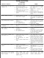
OBSERVED PROBLEM
Burner(s)does not light after
ODS/pilot is lit.
Delayed ignition of burner(s).
Burner backfiring during combustion.
Moisture/condensation noticed
on windows.
Slight smoke or odor during
initial operation.
Heater produces whistling noise
when burner is lit.
Dark residue on logs or inside of
fireplace.
White powder residue forming
within burner box or on adjacent
walls or furniture.
POSSIBLE CAUSE
1. Burner orifice is clogged.
2. Inlet gas pressure is too low.
3. Burner orifice diameter is too
small.
4. Thermocouple leads disconnected
or improperly connected.
5. Burners will not come in remote
position.
1. Manifold pressure is too low.
2. Burner orifice is clogged.
1. Burner orifice is clogged or
damaged.
2. Burner damaged.
3. Gas regulator defective.
1. Not enough combustion/ventila-
tion air.
1. Residues from manufacturing
processes.
2. Not enough air.
3. Gas regulator defective.
1. Turning control knob to Hi position
when burner is cold.
2. Air in gas line.
3. Air passageways on heater
blocked.
4. Dirty or partially clogged burner
orifice.
1. Improper log placement.
2. Rafts or other air currents affecting
flame pattern.
3. Air holes at burner inlet blocked.
4. Burner flame holes blocked.
1. When heated, vapors from
furniture polish, wax, carpet
cleaners, etc. turn into white
powder residue.
REMEDY
1. Clean burner orifice (see Cleaning
and Maintenance) or replace
burner orifice.
2. Contact local propane/LP gas
company.
3. Replace burner orifice.
4. Reconnect leads (see wiring diagram).
5. Replace battery in transmitter and
receiver.
1. Contact local propane/LP gas company.
2. Clean burner (see Cleaning and
Maintenance) or replace burner
orifice.
1. Clean burner orifice (see Cleaning
and Maintenance) or replace it.
2. Replace burner.
3. Replace gas regulator.
1. Refer to Air for Combustion and
Ventilation Requirements (page 4).
1. Problem will stop after a few hours
of operation.
2. Check burner for dirt and debris.
If found, clean burner (see Clean-
ing and Maintenance, page 12).
3. Replace gas regulator.
1. Turn control knob to LO position
and let warm up for a minute.
2. Operate burner until air is removed
from line. Have gas line checked
by local propane/LP gas company.
3. Observe minimum installation
clearances (see pages 6 through 8).
4. Clean burner (see Cleaning and
Maintenance) or replace burner
orifice.
1. Properly locate logs (see Installing
Logs, page 9).
2. Eliminate source of drafts around
heater.
3. Clean out air holes at burner inlet.
Periodically repeat as needed.
4. Remove blockage or replace burner.
1. Turn heater off when using
furniture polish, wax, carpet
cleaner or similar products.

16
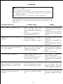
Continued
WARNING: If you smell gas
Shut off gas supply.
Do not try to light any appliance.
Do not touch any electrical switch; do not use any phone in your building.
Immediately call your gas supplier from a neighbor’s phone. Follow the gas
supplier’s instructions.
If you cannot reach your gas supplier, call the fire department.
IMPORTANT: Operating heater where impurities in air exist may create odors.
Cleaning supplies, paint, paint remover, cigarette smoke, cements and glues, new
carpet or textiles, etc, create fumes. These fumes may mix with combustion air and
create odors.
REMEDY
1. Ventilate room. Stop using odor
causing products while heater
is running.
2. Locate and correct all leaks(see
Checking Gas Connections,
page 8).
1. Open window and/or door for
ventilation.
2. Contact local Propane/LP gas
company.
3. Clean ODS/pilot (see Cleaning,
page 12 ).
1. Locate and correct all leaks
(see Checking Gas Connections,
page 8).
2. Replace control valve.
1. Take apart gas tubing and
remove foreign matter
2. Locate and correct all leaks
(see Checking Gas Connections,
page 8).
1. This is common with most
heaters. If noise is excessive,
contact qualified service person.
1. Refer to Air for Combustion and
Ventilation requirements (page
4).
POSSIBLE CAUSE
1. Heater burning vapors from
paint, hair spray, glues, etc.
(See IMPORTANT statement
above).
2. Gas leak. See Warning State-
ment at the top of page.
1. Not enough fresh air is available.
2. Low line pressure.
3. ODS/pilot is partially clogged.
1. Gas leak. See Warning
Statement at the top of page.
2. Control valve defective.
1. Foreign matter between control
valve and burner.
2. Gas leak. See Warning State-
ment at the top of page.
1. Metal is expanding while heat-
ing or contracting while cooling.
1. Not enough combustion/ventilation
air.
OBSERVED PROBLEM
Heater produces unwanted odors.
Heater shuts off in use (ODS
operates).
Gas odor even when control knob
is in OFF position.
Gas odor during combustion.
Heater produces a clicking/ticking
noise just after burner is lit or shut
off.
Moisture/condensation noticed on
windows.

17
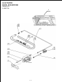
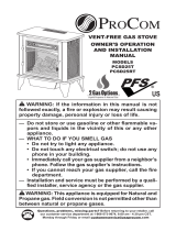
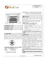
ILLUSTRATED
PARTS BREAKDOWN
SN280TYA
SL280TYA
1

18
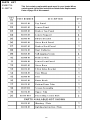
PARTS LIST
SN280TYA
SL280TYA
This list contains replaceable parts used in your heater. When ordering
parts, follow the instructions listed under Replacement Parts on page 13
of this manual.

19
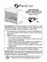
ILLUSTRATED
PARTS BREAKDOWN
SN280TYA
SL280TYA

20
This list contains replaceable parts used in your heater.When
ordering parts ,follow the instructions listed under Replacement
Parts on page 13 of this manual.
PARTS LIST
SN280TYA
SL280TYA
Page is loading ...
Page is loading ...
-
 1
1
-
 2
2
-
 3
3
-
 4
4
-
 5
5
-
 6
6
-
 7
7
-
 8
8
-
 9
9
-
 10
10
-
 11
11
-
 12
12
-
 13
13
-
 14
14
-
 15
15
-
 16
16
-
 17
17
-
 18
18
-
 19
19
-
 20
20
-
 21
21
-
 22
22


Ask a question and I''ll find the answer in the document
Finding information in a document is now easier with AI
Related papers
-
Procom EN250RYLB-O User manual
-
-
-
 ProCom Heating EDP200T-O User manual
-
-
 ProCom Heating RD-C User manual
-
-
 ProCom Heating PCSD25T Installation guide
-
 ProCom Heating FBD28T-J-AS Installation guide
-


Other documents
-
 ProCom Heating QN300TYLA User manual
-
 ProCom Heating EN250TYLA User manual
-
 ProCom Heating SSU220RHN-GB User manual
-
 ProCom Heating FBN400RHA User manual
-
 ProCom Heating FBN280RHAC User manual
-
 Reddy Heater IWH16NLTBDC Installation guide
-
 ProCom Heating SSRD200T-CB User manual
-
 ProCom Heating SSID280T User manual
-
World Marketing of America GSN2821 Owner's manual
-
 Reddy Heater IWH16NLTBDC User manual


