Page is loading ...

1
DESCRIPTION
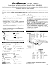
The Cordless Teth-Air is a technologically advanced radio transmitting and receiving safety device. It is designed
for snowmobiles and similar vehicles where the rider/driver may get separated from the controls. This system is
designed to shut off the engine in a runaway condition, whether the throttle is stuck open or when the vehicle may be
kept moving, aided by the engine running uncontrolled in gear.
The Cordless Teth-Air is comprised of two components:
1. Transmitter. (Worn on the wrist of the vehicle operator)
2. Receiver. (Mounted and wired permanently on the vehicle)
The primary mode/feature of operation is to shut off the vehicle engine when the driver is ejected from the drivers
seat or falls off the vehicle. The receiver will shut the engine off when the radio signal strength is too weak. This
condition occurs when the distance from the transmitter and receiver become too great. The ideal set-up condition
allows uninterrupted operation of the vehicle as long as the transmitter on the operator is within 2-3 metres (6-9 feet)
of the receiver.
The secondary mode/feature of operation is to provide limited theft control of your vehicle. When properly
installed, the Cordless Teth-Air does not allow operation of the engine for more than 1 second without receiving the
coded digital signal from the transmitter. This allows the engine to start but does not allow sufficient running time
for a potential thief to ride away.
1
2
COR
DLES
S
TETH-AIR
TM

2
CERTIFICATION
This device complies with part 15 of the FCC Rules. Operation is subject to the following two conditions: (1) This
device may not cause harmful interference, and (2) this device must accept any interference received, including
interference that may cause undesired operation.
CAUTION
Changes or modifications not expressly approved by the party responsible for compliance could void the user's
authority to operate the equipment.
Note: This equipment has been tested and found to comply with the limits for a Class B digital device, pursuant to
part 15 of the FCC Rules. These limits are designed to provide reasonable protection against harmful interference in
a residential installation. This equipment generates, uses and can radiate radio frequency energy and, if not installed
and used in accordance with the instructions, may cause harmful interference to radio communications. However,
there is no guarantee that interference will not occur in a particular installation. If this equipment does cause harmful
interference to radio or television reception, which can be determined by turning the equipment off and on, the user
is encouraged to try to correct the interference by one or more of the following measures:
—Reorient or relocate the receiving antenna.
—Increase the separation between the equipment and receiver.
—Connect the equipment into an outlet on a circuit different from that to which the receiver is connected.
—Consult the dealer or an experienced radio/TV technician for help.
PATENT PROTECTION
This device is protected under the following patent(s): Patent License US 7,034,696 B2

3
INSTALLATION
Receiver:
The receiver is housed in a water resistant ABS enclosure. However, is recommended to be installed in a dry
location. Make sure that the chosen location is not to close to HOT ENGINE OR EXHAUST SYSTEM
components. The internal relay will accommodate normally open or normally closed kill switch wiring schemes.
The normally open configuration would be used when it is desired to “close” the “kill switch” to stall the engine
(e.g. Ski-doo and Polaris snowmobiles). The normally closed configuration would be used “open” the “kill switch”
to stall the engine (e.g. Arctic Cat snowmobiles and vehicles with a battery type electrical system).
The receiver requires a 6-18 volt supply from the vehicles power source. The power can be either AC or DC
(therefore not polarity sensitive) and should not supply power when the engine is off (e.g. not across battery). If the
vehicle is equipped with an ignition switch, you may connect the receiver unit at the switched side of the ignition
switch. The white and yellow wires on the receiver unit are used for the power connection. Tie these wires in to the
chosen power supply location with the supplied connectors. See wiring diagram for further details.
Install the antenna (stripped end of COAX) as close as possible to the throttle side handgrip with the supplied zip
ties. For best reception it is recommended to not attach to metal surfaces or have metal components in the path
between the transmitter and receiver. Do not install COAX antenna where it could impede throttle operation.
The receiver is shipped with the 6.5cm (2.5”) antenna for maximum operational area. The antenna length may be cut
shorter to decrease the operating area. If this is done it is recommended to cut about 1cm (3/8“) at a time and not
shorter than 2cm (3/4“). Test your operational area by starting engine and walking away and monitoring where the
engine cuts out. Keep shortening the antenna until you are satisfied with the operation. If you overshoot and cut the
antenna too short, re-strip the black COAX jacket and shield to the desired length. Remember to keep the white
inner insulator on the antenna.
Transmitter:
The transmitter PCB is coated with a water resistant epoxy that is housed in a water resistant ABS enclosure with no
user interface buttons. The TAG must be worn on the outside of the clothing for best results. For abnormally wet
riding conditions, it is still recommended to apply a thin bead of silicon sealant to the battery cover before
installation. This will have to be checked or re-applied each time the battery cover is removed.
To install the battery, remove the two screws from the back of transmitter and install the supplied battery (CR2032).
Replace the cover and screws.
Affix the wrist strap to the back of the transmitter as shown in figures A, B and C on the next page with the hook
and latch material supplied.

4
TAG STRAP INSTALLATION
A
B
C
Remove the black “hook” material (illustration “A”)
from the paper backing and adhere it to the bac
k
center of the TAG.
____________________________________
Feed the elastic “latch” material through one side o
f
the flange opening of the TAG. Then attach the
“latch” material to the “hook” material as shown i
n
illustration “B”.
____________________________________
Feed the other side of the “latch” material through
the other flange opening and attach it to the “hook”
material. Same as illustration “B”.
The final result of the TAG should look like the
illustration in “C”.
The length of the “latch” material may be shortene
d
to suite you individual needs by pulling the “latch”
material through one side of the flange further, an
d
re-attaching it to the “hook” material. Cutting the
“latch” material is not recommended incase you will
need it to be longer in the future. Remember, the
TAG has to be worn outside the clothing for bes
t
results.
________________________________
For further information please see our web site @ :
www.sourceinnovations.ca.

5
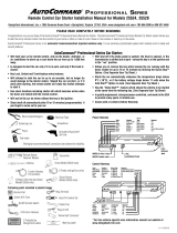
WIRING DIAGRAM
POWER (6V to 18V AC/DC)
YL = YELLOW
WH = WHITE
RELAY
GY = GREY (normally closed)
GR = GREEN (common)
BR = BROWN (normally open)
NOTE
INSTALLER CONNECTIONS
A:
B: CUT EXISTING WIRE
THE POWER SUPPLY LOCATION MUST NOT SUPPLY POWER WHEN THE ENGINE IS
OFF FOR VEHICLES WITHOUT IGNITION SWITCHES (SEE INSTALLATION).
*
:
Normally Open Configuration
e.g. Ski-doo, Polaris, new Artic Cat Normally Closed Configuration
e.g. old Arctic Cat & Battery Ignition
Existing Kill
Switch
GR BR
RECEIVER
UNIT
Existing Kill
Switch
RECEIVER
UNIT
Existing Wiring
}Existing Wiring
}
YL WH YL WH
A A B
A
A
GR GY
Vehicle Power
*
Vehicle Power
*

6
OPERATION / SETUP
Transmitter
The transmitter unit is to be worn on outer most layer of clothing around the wrist of rider/driver. Use the right wrist,
as this one is closest to the throttle where the COAX antenna is mounted. Obstructions of clothing may affect the
range of the transmitter. There are no user buttons on the transmitter for set up. When the battery is installed, this
unit runs until battery is removed or exhausted. A fresh battery will last up to 6 months with continuous use
depending on ambient temperature. To extend battery life, it is a good idea to remove the battery from transmitter
during extended periods of non-use.
Receiver
The receiver has a three status LED indicator and a push button on the enclosure. The LED will blink green during
normal operation, blink orange when the battery becomes low during normal operation and solid red during TAG
signal loss. The battery should be replaced soon after when the LED blinks orange for continued operation.
The push button is used for transmitter TAG setup and bypass mode. The first time that the Cordless Teth-Air is
used, the supplied TAG must be “learned” by the receiver unit. To do this, make sure that the battery is installed in
the TAG and the tag is close to the COAX antenna. With in 30cm or 1 foot. Start the engine and depress the push
button on the receiver unit within 1 second or hold it down while starting. The LED indicator will now be solid
green indicating “learn / bypass” mode. Wait a few seconds and press the push button again to register the TAG. The
LED will back to blinking green and you will be ready to go. After this initial set up, the Cordless Teth-Air will
always be ready during every engine start up. More TAG’s may be registered as needed at any time engine is
running (max. 6 TAG’s). Just place all TAG’s to be registered with in 30cm (1 foot) and depress the push button.
After indicator LED shows solid green, wait a few seconds press the button again. Now all TAG’s in range may
operate the vehicle. This may be done multiple times to go back and forth between TAG’s. Pushing the “set up /
bypass” mode button after 1 second during engine start up also sets the Receiver unit in bypass mode if the push
button is not depressed. This disables the system and the engine is operated as if there was no Cordless Teth-Air is
installed. This bypass mode is mainly used if TAG becomes lost or has a dead battery. To keep engine in bypass
mode, this procedure has to be preformed every time engine is started up. With no TAG present or registered, the
engine will approximately run for 1 second and shut down.
When power to the receiver unit is taken from the ignition switch, (vehicles with electric start) the ignition must be
toggled off in order to reset the receiver unit. The engine will not start when the status LED is red. Turn key off and
wait for approximately 3 seconds until LED goes out and then you can re-start engine.
The Cordless Teth-Air is a tool to make your vehicle safer and more enjoyable to use. Source Innovations Ltd.
makes no claims or guarantees regarding results as radio interference is possible and cannot be controlled. See
disclaimer for further details
ALWAYS TEST OPERATION PRIOR TO USE by starting engine and walking away from vehicle with TAG.
/