Page is loading ...

CONTENTS ...........................................................................PAGE
Dimensions...................................................................................2
Installation Requirements:
Boiler Location........................................................................ 3
Boiler Foundation.................................... ............................... 3
Chimney Requirements............................. ............................. 3
Minimum Clearance................................................................. 3–4
Vent Piping.............................................................................. 4
Gas Piping............................................. ...................................... 4
Boiler Room Air Supply and Ventilation.................................. 5
Draft Hood Installation............................................................ 5
Piping at Boiler—Water Boilers................... ........................... 5
Steam Controls Assembly and Installation............................. 6
Piping a Steam Boiler ......................................................... 6, 7
Vent Damper.................................................................. 7, 8, 12
Electrical Controls and Wiring.................... ............................ 9
Pump or Valve Zoning—Water Boilers.............. .................. 10–11
Boiler Water Temperature Control .......................................12–13
Operating Instructions:
Filling and Venting Water Systems....................................... 14
Initial Start, Safety and Lighting Instructions... ..................... 15
Burner Adjustment, Checking Gas Input.............................. 15
Controls, Safety Check......................................................... 17
Low Water Cut-off Check-Out.................................................... 17
Pressure Control Check-Out ..................................................... 17
Blowing Off a Steam Boiler........................................................ 17
Care and Maintenance.................................. ............................ 18
Safety Check for Control System................ ......................... 18
Protection From Freezing.......................... ........................... 18
Water Treatment.....................................................................18
Sequence of Operations............................................................ 21
Troubleshooting Guide...............................................................22
Appendix A & B.......................................................................... 23
Appendix C, D & E......................................................................24
Printed in Canada 0713 PUBLICATION GG-41
Part No. 41-0549 Revision B
INSTALLATION AND OPERATING INSTRUCTIONS
HOT WATER—Models GG-75H through GG-399H
LOW PRESSURE STEAM AND HOT WATER— Models GXH-105 through GXH-300H
GALAXY
GAS-FIRED CAST IRON BOILERS FOR NATURAL AND L.P. PROPANE GASES
IMPORTANT
READ ALL OF THE FOLLOWING WARNINGS AND
STATEMENTS BEFORE READING THE INSTALLATION
INSTRUCTIONS.
The installation must conform to the requirements of the
authority having jurisdiction or, in the absence of such
requirements, to the National Fuel Gas Code, ANSI Z223.1-
latest edition or CSA B 149.1 latest edition for natural gas
and propane. The installation must also conform to the
additional requirements in this Slant/Fin Instruction Book.
In addition, where required by the authority having juris dic -
tion, the installation must conform to American Society of
Mechanical Engineers Safety Code for Controls and Safety
Devices for Automatically Fired Boilers, No. CSD-1 or CSA B
149.1 latest edition for natural gas and propane. If there is
any conflict in the above requirements, then the more
stringent requirement will apply.
This manual must be left with owner and should be hung on
or adjacent to the boiler for reference.
WARNING
This boiler, gas piping and accessories must be installed,
connected, serviced and repaired by a trained, experienced
service technician, familiar with all precautions required for
gas-fired equipment and licensed or otherwise qualified, in
compliance with the authority having jurisdiction.
Heating Contractor
Address
Phone Number
Boiler Model Number
Boiler Serial Number
Installation Date
WARNING
SEE "WARNING" ON PAGE 3
FOR LIQUEFIED PETROLEUM (L.P.)
PROPANE GAS-FIRED BOILERS

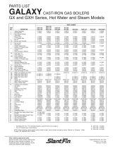
ORIFICE SIZES indicated for Sea Level are factory installed in boiler unless other-
wise specified by the local authority.
See page 15 for burner adjustment.
GAS VALVE CONNECTION Size is 1/2" f.p.t. for all sizes up to and including GG-
125 and GXH-125 depending upon configuration (natural, L.P., IID). Larger boilers,
gas valves are 3/4".
COMBUSTIBLE FLOOR KIT increases all height dimensions by 51 mm (2").
RAISED SLAB—When mounting boiler on a raised slab, the slab must extend at
least 51 mm (2") beyond the boiler cabinet on all sides.
CHIMNEY HEIGHT: 4.5 m (15 ft.) minimum from draft hood skirt to top of chimney.
CHIMNEY INSIDE DIAMETER must be same as Dimension “C” or larger. Larger
diameter and/or height may be required if two or more boilers or a boiler and
another appliance are vented to a single chimney.
GG-75H GG-100H GG-125H GG-150H GG-175H GG-200H GG-225H GG-250H GG-275H GG-300 GG-325 GG-350 GG-350H GG-375 GG-375H GG-399H
Field Control (Effikal) Vent Damper
C H I
127mm 152mm 122mm
(5") (6") (4-13/16")
152mm 165mm 135mm
(6") (6-1/2") (5-5/16")
178mm 179mm 149mm
(7") (7-1/16") (5-7/8")
203mm 205mm 175mm
(8") (8-1/16") (6-7/8")
228mm 276mm 225mm
(9") (10-7/8") (8-7/8")
254mm 327mm 276mm
(10") (12-7/8") (10-7/8")
GXHA-100 GXH-105 GXH-125GXHA-120 GXH-150 GXH-170GXHA-160 GXH-190 GXH-210GXHA-200 GXH-230 GXH-250 GXH-275 GXH-300 GXH-300H
321/2
261/16
8
675/8
25
143/4
11/4
21/2
31/2
93/4
3/4
321/2
261/16
9
591/8
15
143/4
11/4
21/2
31/2
93/4
3/4
GXH SERIES STEAM AND HOT WATER BOILERS - DIMENSIONS IN MM FOLLOWED BY INCHES
193/4
133/16
5
463/8
63/4
8
11/4
11/2
23/4
91/4
502
335
152
1353
330
203
70
235
193/4
133/16
6
531/4
13
8
11/4
11/2
23/4
91/4
502
335
152
1353
330
203
70
235
193/4
133/16
6
531/4
13
8
11/4
11/2
23/4
91/4
584
421
152
1353
330
248
70
235
23
169/16
6
531/4
13
93/4
11/4
11/2
23/4
91/4
584
421
152
1353
330
248
70
235
23
169/16
6
531/4
13
93/4
11/4
11/2
23/4
91/4
673
506
178
1461
406
286
70
235
261/2
1915/16
7
571/2
16
111/4
11/4
11/2
23/4
91/4
673
506
178
1461
406
286
70
235
261/2
1915/16
7
571/2
16
111/4
11/4
11/2
23/4
91/4
756
592
203
1514
432
330
70
235
293/4
235/16
8
595/8
17
13
11/4
11/2
23/4
91/4
756
592
203
1514
432
330
70
235
293/4
235/16
8
595/8
17
13
11/4
11/2
23/4
91/4
845
662
203
1514
432
375
70
235
331/4
261/16
8
595/8
17
143/4
11/4
11/2
23/4
91/4
845
662
203
1680
432
375
70
235
331/4
261/16
8
661/8
17
143/4
11/4
11/2
23/4
91/4
927
764
229
1680
572
413
70
235
361/2
301/16
9
661/8
221/2
161/4
11/4
11/2
23/4
91/4
927
764
229
1680
572
413
70
235
361/2
301/16
9
661/8
221/2
161/4
11/4
11/2
23/4
91/4
927
764
254
1680
381
413
70
235
361/2
301/16
10
661/8
221/2
161/4
11/4
11/2
23/4
91/4
927
764
229
1680
381
413
70
235
361/2
301/16
9
661/8
221/2
161/4
11/4
11/2
23/4
91/4
927
764
254
1680
457
413
70
235
361/2
301/16
10
661/8
221/2
161/4
11/4
11/2
23/4
91/4
2 GALAXY
GG SERIES HOT WATER BOILERS—DIMENSIONS IN MM FOLLOWED BY INCHES
GG Natural 42 43 43
Except GG-399H Propane 54 55 55
GG-399H Natural 40 42 42
Propane 53 54 54
GXH-105 Natural 44 43 45
through 275 Propane 54 55 55
GXH-300 Natural 43 44 44
Propane 55 54 56
GXH-300H Natural 43 44 44
GG-350H Gas*
BOILER MODEL GAS TYPE
ORIFICE SIZES AT HIGH ALTITUDES
610 to 1219 m
(2000 to 4000 ft.)
1219 to 1372 m
(4000 to 4500 ft.)
Orifice Size for
Sea Level
*For L.P. Propane gas, consult factory.
FRONT VIEW
All GG and GXH
Alternate 1-1/2"
return (except
GG-75 thru
GG-175
Pressure Relief
Valve
3/4"
273 mm
(103/4")
832 mm
(323/4")
Install Man-
ual Shut-
Off Valve
1524 mm (5
ft.) Above
When
Required
By Local
Code
622 mm
(241/2")57 mm
(21/4")
57
mm
(21/4")
419 mm
(161/2")
318
mm
(121/2")
660
mm
(26")
70
mm
(2
3
/
4
")
1-1/4"
Tapping on
Steam Boilers
673 mm
(261/2")660
mm
(26")
152 – 327 mm (6 – 12-7/8")
1/2" Vent
Tapping
RIGHT SIDE
GG / GXH-PT
RIGHT SIDE
GXH-PZT-PPZT
RIGHT SIDE
GXH--PZ-PZT-PPZT
Tankless Heater
Connections "L"
except GXH-PZ
Tankless Heater
Connections "L"
GXH-PT only
RIGHT SIDE
GG / GXH-PT
FRONT VIEW
All GG and GXH
LEFT SIDE
All GG and GXH
RIGHT SIDE
GXH-PZ
A
B
C
D
E
F
G
H
J
K
A
B
C
D
E
F
G
H
J
K
L
M
584
421
127
1178
171
248
89
248
23
169/16
5
463/8
63/4
93/4
11/4
21/2
31/2
93/4
1/2
419
127
254
161/2
5
10
419
127
254
161/21/4
5
10
584
421
152
1353
330
248
89
248
23
169/16
6
531/4
13
93/4
11/4
21/2
31/2
93/4
1/2
673
506
178
1410
356
286
89
248
261/2
1915/16
7
551/2
14
111/4
11/4
21/2
31/2
93/4
1/2
673
506
178
1410
356
286
89
248
261/2
1915/16
7
551/2
14
111/4
11/4
21/2
31/2
93/4
1/2
673
506
178
1410
356
286
89
248
261/2
1915/16
7
551/2
14
111/4
11/4
21/2
31/2
93/4
1/2
756
592
178
1410
356
286
89
248
293/4
239/16
7
551/2
14
111/4
11/4
21/2
31/2
93/4
3/4
727 285/8727 285/8
508
152
298
20
6
11
727 285/8
756
592
178
1410
356
330
89
248
293/4
239/16
7
551/2
14
13
11/4
21/2
31/2
93/4
3/4
826
662
178
1410
356
375
89
248
321/2
261/16
7
551/2
14
143/4
11/4
21/2
31/2
93/4
3/4
826
662
178
1410
356
375
89
248
321/2
261/16
7
551/2
14
143/4
11/4
21/2
31/2
93/4
3/4
826
662
203
1718
635
375
89
248
826
662
229
1502
381
375
89
248
502
335
127
1178
171
203
70
235
337 mm
(131/4")
76
mm
(3")
184 mm
(
21/4"
)
648 mm
(251/2")
419 mm
(161/2")
184
mm
(71/4")
70 mm
(2
3
/
4
")
Return Tap-
ping G on
right side of
boiler
318 mm
(121/2")
3/4
591
178
343
23
7
13
727 285/8
1/2

GALAXY GG SERIES
GALAXY 3
INSTALLATION REQUIREMENTS
The installation must conform to the requirements of the author-
ity having jurisdiction or, in the absence of such requirements,
to the National Fuel Gas Code, ANSI Z223.1-latest edition or
CSA B 149.1 latest edition for natural gas and propane.
This installation must also conform to the additional require-
ments in this Slant/Fin instruction book. Installation and service
to be performed by a qualified installer, service agency or the
gas supplier.
NATURAL GAS-FIRED BOILER LOCATION—
Provide a level, solid foundation for the boiler. Location should
be as near the chimney as possible so that the flue pipe from
boiler to chimney is short and direct.
Automatic gas ignition system components shall be installed so
these components will not be subjected to dripping water dur-
ing installation or service.
CHIMNEY REQUIREMENTS—
A. Galaxy boilers may be vented into a masonry vitreous tile-
lined chimney UL listed or Type “B” Venting system NOT
EXPOSED to the OUTDOORS below the roof line.
Venting and sizing of venting system must be in accordance
with the requirements of the local gas utility, local building
codes and other authorities having jurisdiction.
If a masonry chimney is exposed to the outdoors on one or
more sides below the roof line (exterior chimney), ONE of the
following options apply:
1. Chimney must be re-lined with an approved metallic liner.
When this is done, the chimney UL listed will be considered
NOT exposed to the outdoors and the requirements of the
National Fuel Gas Code for NON-exposed chimneys
and/or local codes will apply.
2. If an UL listed exposed tile-lined chimney is to be used
WITHOUT a metallic liner, the boiler must first meet the
requirements of the following tables and paragraphs of the
National Fuel Gas Code:
I. For Single Galaxy Boiler—Paragraph 11.2.9 and table
11.11.
II. For multiple appliances—Paragraph 11.3.18 and table
11.12 (or 11.13 if applicable).
In addition, all requirements of the local gas utility, local
building codes and other authorities having jurisdiction
apply.
B. If an existing boiler is removed from a common venting sys-
tem, the common venting system may be too large for proper
venting of the remaining appliances connected to the com-
mon vent. Follow the test procedure shown in Appendix "A"
on page 23 of this manual to insure proper operation of vent-
ing system and appliances.
C. Inspect for proper and tight construction. Any restrictions or
obstructions must be removed. An existing chimney may
require cleaning.
D. Chimney or vent must extend at least 914 mm (3 feet) above
its passage through a roof and at least 914 mm (3 feet) above
any ridge within 3048 mm (10 feet) of the chimney.
MINIMUM CLEARANCES FROM COMBUSTIBLE
CONSTRUCTION —
A. Minimum boiler clearances shall be as follows:
BOILER FOUNDATION
A. Provide a solid, level foundation, capable of supporting the
weight of the boiler filled with water, and extending at least
51 mm (2") past the jacket on all sides. See dimensions of
boilers, page 2.
B. For installation on non-combustible floors only.*
C. If boiler is to be located over buried conduit containing
electric wires or telephone cables, consult local codes
or the National Board of Fire Underwriters for specific
requirements.
* The Combustible Floor Kit part number printed on the boiler rating plate is
the only one to be used when installing on combustible floors. The boiler
must NOT be installed on carpeting.
DO NOT place boilers above floor area containing radiant tubing.
MODELS GG-75H
THROUGH GG-225H.
MINIMUM CLEARANCE
FOR COMBUSTIBLE
CONSTRUCTION.
MINIMUM CLOSET
CLEARANCE.
Front 152 mm (6")
Rear 152 mm (6")
Left Side 152 mm (6")
Right Side 152 mm (6")
Top 914 mm (36")*
Flue
Connector 152 mm (6")
Type 'B' Vent 25 mm (1")
MODELS GG-250
THROUGH GG-399H.
MINIMUM CLEARANCE
FOR COMBUSTIBLE
CONSTRUCTION.
MINIMUM ALCOVE
CLEARANCE.
Front Alcove
Rear 152 mm (6")
Left Side 152 mm (6")
Right Side 152 mm (6")
Top 914 mm (36")*
Flue
Connector 152 mm (6")
Type 'B' Vent 25 mm (1")
* Allow extra clearance from combustibles for additional venting.
WARNING
SPECIAL ATTENTION FOR LIQUEFIED
PETROLEUM(L.P.)
PROPANE GAS-FIRED BOILER INSTALLATIONS
LPG appliances (boilers) shall be installed in
accordance with applicable provisions of NFPA 58
(Liquefied Petroleum Gas Code) latest edition for
installations in US and CAN/CGA B149.1 latest
edition for installations in Canada
Liquefied Petroleum (LP) propane gas is heavier than
air therefore Propane gas can accumulate at floor level.
If you suspect a leak, do not attempt to operate boiler.
A spark or flame from the appliance (boiler) or other
sources may ignite the accumulated propane gas
causing an explosion or fire. It is recommended that
inspections for gas leaks be performed periodically by
a licensed professional and that leak detection devices
be installed as a further safety measure.

GALAXY GXH SERIES
4 GALAXY
* Allow extra clearance from combustibles for additional venting.
B. Provide accessibility clearance of 610 mm (24") on sides
requiring servicing and 457 mm (18") on sides used
for passage.
C. All minimum clearances shown above must be met. This may
result in increased values of some minimum clearances in
order to maintain the minimum clearances of others.
D. Clearance from steam and hot water pipes shall be
25 mm (1"). **
** At points where hot water or steam pipes emerge from a floor, wall or ceil
ing, the clearance at the opening through the finished floor boards or wall
or ceiling boards may be not less than 13 mm (1/2"). Each such opening
shall be covered with a plate of noncombustible material.
SAFETY—
VENT PIPING—
A. Vent piping installation must be in accordance with the
requirements of the local gas utility, local building codes and
other authorities having jurisdiction.
B. Boiler vent pipe must be the full diameter of the boiler draft
hood outlet. See dimensions, page 2. If a vent damper is
added, its diameter must be equal to the hood outlet and
must be located past the hood outlet. See installation
instructions furnished with vent damper and in the section
"Vent Damper Installation" of this instruction book.
C. If more than one appliance vents into a common breeching,
the area of the breeching must be equal to the area of the
largest vent plus 50% of the area of the additional vent areas.
Vent connectors serving appliances vented by natural draft
shall not be connected into any portion of mechanical draft
systems operating under positive pressure. Horizontal
breeching or vent pipe should be as high as possible, con-
sistent with codes, so that vertical vents from appliances will
have a high rise above draft diverter openings. All horizontal
runs must slope upwards not less than 20 mm/m (1/4inch per
foot) of run. Horizontal portions of the venting system must
be supported to prevent sagging by securing each joint with
metal screws and by providing hangers spaced no greater
than 1524 mm (5 feet) apart.
D. Vent or breeching into chimney should not be inserted past
the inside wall of the chimney liner.
E. All venting means should be inspected frequently. See Care
and Maintenance and separate User's Information Manual.
GAS PIPING—
A. Local installation codes apply. The pipe joint compound used on
threads must be resistant to the action of liquefied petroleum gases.
B. The gas supply line to the boiler should be run directly from the
meter for natural gas or from the fuel tank for L.P. propane gas. See
page 2 for location of union and manual main shut-off valve that may
be specified locally.
Selecting pipe size for natural gas:
1. Measure or estimate the length of piping from the meter to the
installation site.
2. Consult gas supplier for heating value of gas-W/m3(BTU/cu. ft.).
3. Divide boiler rated input by heating value to find gas flow in pip-
ing (m3/hr) (cu. ft. per hour).
4. Use table below to select proper pipe size.
Example: Boiler model GG-300 is to be installed. Distance from gas
meter to the boiler is 15.24 m (50 ft). Heating value of natural gas is
10560 W/m3(1020 BTU/cu. ft.) Select proper pipe size.
At 15.24 m (50 ft.) length of pipe, match required capacity from
table below (choose higher capacity, in this case 12.5 m3(440 cu.
ft.) per hour). Required pipe size is 11/4".
Improper gas pipe sizing will result in pilot flame outages, insuffi-
cient heat and other installation difficulties. For more information
and also if other appliances are to be attached to the piping system,
see Appendix C of National Fuel Gas Code ANSI Z223.1-latest edi-
tion or
CSA B 149.1 latest edition for natural gas and propane
.
C. The boiler and its gas connection must be leak tested before plac-
ing the boiler in operation. Use liquid soap solution for all gas leak
testing. DO NOT use open flame.
This boiler and its individual shutoff valve must be disconnected
from the gas supply piping system during any pressure testing of
that system at test pressures in excess of 3.5 kPa (1/2PSIG). This
boiler must be isolated from the gas supply piping system by clos-
ing its individual manual shutoff valve during any pressure testing
of the gas supply piping system at test pressures equal to or less
than 3.5 kPa (1/2PSIG).
D. All gas piping used should be inspected thoroughly for cleanliness
before makeup. A sediment trap must be provided, as illustrated on
page 2.
E. The minimum and maximum gas supply pressure (at the inlet of gas
valve) are shown on the boiler rating plate for the type of gas used.
Gas supply pressure should never be less than minimum or more
than maximum pressure when the boiler or any other appliance is
turned on or off.
MODELS GXH-105
THROUGH GXH-190
MINIMUM CLEARANCE
FOR COMBUSTIBLE
CONSTRUCTION.
MINIMUM CLOSET
CLEARANCE.
Front 152 mm (6")
Rear 152 mm (6")
Left Side 152 mm (6")
Right Side 457 mm (18")
Top 914 mm (36")*
Flue
Connector 152 mm (6")
Type 'B' Vent 25 mm (1")
MODELS GXH-210 TO
GXH-300H.
MINIMUM CLEARANCE
FOR COMBUSTIBLE
CONSTRUCTION.
MINIMUM ALCOVE
CLEARANCE.
Front Alcove
Rear 152 mm (6")
Left Side 152 mm (6")
Right Side 457 mm (18")
Top 914 mm (36")*
Flue
Connector 152 mm (6")
Type 'B' Vent 25 mm (1")
KEEP THE BOILER AREA CLEAR AND FREE FROM
COMBUSTIBLE MATERIALS, GASOLINE AND OTHER
FLAMMABLE VAPORS AND LIQUIDS.
Gas flow = = 8.3 m3/hr
87 930 W/hr
10 560 W/m3
(Gas flow = = 294 cu. ft. per hour)
300,000 BTU/hour
1020 BTU/cu. ft.
1/2"3/4"1"1
1/4"1
1/2"
mft
m3/hr cu.ft./ hr. m3/ hr cu.ft./ hr. m3/ hr cu.ft./hr. m3/hr cu.ft./ hr. m3/hr cu.ft./hr.
3.0 10 3.7 132 7.9 278 14.7 520 29.7 1050 45.3 1600
6.1 20 2.6 92 5.4 190 9.9 350 20.7 730 31.1 1100
9.1 30 2.1 73 4.3 152 8.1 285 16.7 590 25.2 890
12.2 40 1.8 63 3.7 130 6.9 245 14.2 500 21.5 760
15.2 50 1.6 56 3.3 115 6.1 215 12.5 440 19.0 670
18.3 60 1.4 50 3.0 105 5.5 195 11.3 400 17.3 610
21.3 70 1.3 46 2.7 96 5.1 180 10.5 370 15.9 560
24.3 80 1.2 43 2.5 90 4.8 170 9.9 350 15.0 530
27.4 90 1.1 40 2.4 84 4.5 160 9.1 320 13.9 490
30.5 100 1.1 38 2.2 79 4.2 150 8.6 305 13.0 460
Length
of Pipe
Gas Flow In Piping
Pressure drop=8mm(0.3") water column, 0.60 specific gravity gas.
Iron Pipe Size (Ips) inches
At pressure drop of 0.3 in. water, specific gravity = 0.60 gas.

GALAXY 5
BOILER ROOM AIR SUPPLY AND VENTILATION
An ample supply of air is required to obtain combustion and ven-
tilation. ALL AIR COMES FROM OUTSIDE, directly through wall
openings to the boiler or through unsealed openings around win-
dows, doors, etc. in the whole building. When buildings are insu-
lated, caulked and weather stripped, now or later on, direct
openings to outside may be required and should be provided. If
the boiler is not near an outside wall, air may be ducted to it from
outside wall openings.
Provisions for combustion and ventilation air must be made in
accordance with section 5.3, Air for Combustion and Ventilation,
of the National Fuel Gas Code, ANSI Z223.1-latest edition or CSA
B 149.1 latest edition for natural gas and propane, or applicable
provisions of the local building codes. The following recommen-
dation applies to buildings of energy-saving construction, fully
caulked and weather stripped:
INSTALLATION IN ENCLOSED BOILER ROOM REQUIRES
TWO UNOBSTRUCTED OPENINGS FOR PASSAGE OF AIR
INTO THE BOILER ROOM:
A. Air drawn horizontally from outdoors DIRECTLY through
an outside wall; one louvered opening near the floor and
one louvered opening near the ceiling, each opening with a
minimum FREE air passage area of 550 mm2per kW (1
square inch per 4000 BTUH) of total appliances’ input.
B. Air drawn horizontally through HORIZONTAL DUCTS;
one opening near the floor and one opening near the ceiling,
each opening with a minimum FREE air passage area of
y Sgintainlimir EA
mets
YPPLSU
TCT HOREDI
NGIHAS WTO
NER LATEWT
SNEIACH MNG
EATLD WCO
YPPLSU
EDERPEMT
RATET WHO
R
WFLO
ALVV
TURNRE
L NTRO COW
DEUSF , IEALV
YPPLSU
NMA
TURN
PUMP
W
REP
NT ER VAI
CATIMAUTO
D ANDEER FATEW
NGDUCI REURESSRE
RNATEALTE
NCATIO LOPUMP
NTRO
CO
W
W
FLO
USF , IEALVV
TURNRE
UMP
MHRAGAPDI
ONIESSPROMC
TANK
L NTRO
DEUS
PUM
RNATEALTE
CATILO
P MUP
CATIMAUTO
NTER VAI
YPPLSU
INMA
RNATE
NOCATI RATEW
EEDF SSTANKLE
RATEHE
S
RATET WHO
STURE FIXTO
NGRIEPMTE
EALVV
DUCI REURESSREP
S)ERHY OT(BVE LVA
D ANDEER FATEW
RNATEALTE
PUMPREP
VA
NG
S)
NGDUCI REURESSRE
S)ERHY OT(BVE LVA
DEFERATE WRNATEALTE
BY(EALV VNGDUCIRE
URESSREAND P
)RSTHEO
UMP
NATIIBMCO
VE LVA
URESSREP
ALVLL VFI
RPMCO
HRAGAPDI
PUM
NONATI
S)ERHY OT(B
NGDUCI REURE
AND EALV
TANK,NOISSER
MHRAG NTROCOWFLO
esknato teziS(
TENO
rtewa
EALVL VNTRO
)ytciap calio cses
NDRAI
lo cow beevla vngirpeme tllatnsI:TE
rteaehet toln ir
d
1100 mm2per kW (1 square inch per 2000 BTUH) of total
appliances’ input.
C. Air drawn VERTICALLY from outdoors; one opening at the
floor and one opening at the ceiling, each opening with a
minimum FREE air passage area of 550 mm2per kW (1
square inch per 4000 BTUH) of total appliances’ input.
D. Air drawn from inside the building; one opening near the
floor and one opening near the ceiling, each opening with a
minimum FREE air passage area of 2200 mm2per kW (1
square inch per 1000 BTUH) of total appliances’ input.
DRAFT HOOD—
The draft hood supplied is part of the listed boiler assembly. DO
NOT alter the hood. See dimensions, page 2.
Attach the hood to the boiler flue outlet. Connect flue pipe full
size of hood outlet. If a vent damper is added, it must be
installed on the outlet side of the hood. See Vent Piping on
page 4,7 and 8 ( Figures 4, 5, 6,7 ).
PIPING AT BOILER — WATER PIPING
A. CIRCULATING SYSTEMS
1. Packaged water boilers are equipped with a water circulat-
ing pump, mounted to return the water into the boiler. For
some installations, the pump should be on the supply
main. See PUMP LOCATION, on page 6.
B. AIR CONTROL SYSTEM
1. DIAPHRAGM-TYPE COMPRESSION TANKS are used to
SPECIAL FLUSHING INSTRUCTIONS
Installation of new boiler may break loose a heavy
accumulation of sediment and scale from old pip
ing and radiators. It is extremely important to blow
down your McDonnell Cut off 67 more frequently
the first week.
First week 3 times
Thereafter at least once a week
* Exception: McDonnell Cut off 42A must be blown
down daily.
See "CARE & MAINTENANCE" for instructions.
3/4" RELIEF
VALVE
3/4" RELIEF
VALVE
1/2" O.D. TUBE
CUT TO SIZE
AT THIS END
5/8" COMP. ADAP.
FITTING
1/4" × 1/4" × 1/4"
1/4" SIPHON
3/8" MALE PIPE TO 1/2"
O.D. COMP. ADAP.
NIPPLE
1/2 × 2"
TEE
1/2× 1/2× 1/2"
TEE 1/2× 5/8" ADAPTER
NIPPLE
1/2× 51/2" THD AT
BOTH ENDS
NIPPLE 1/4× 21/2"
ADAPTER
WATER LEVEL
648 mm (251/2")
OFF FLOOR
ELBOW
1/4" × 90°
NIPPLE 1/4" ×
CLOSE
NIPPLE
1/2× 6" THD AT
BOTH ENDS

control system pressure in an AIR ELIMINATING SYSTEM:
an automatic air vent is used to REMOVE air from the sys-
tem water. See illustration on page 5.
If system pressure needs further control, add an additional
tank or install a larger capacity tank.
Locate the tank near the boiler, as illustrated.
An automatic air vent should be installed in the top of the
boiler. See illustration on page 5.
2. PUMP LOCATION — Locating low-head pump(s) on return
to boiler is acceptable for smaller boiler sizes in resi -
dences of one or two stories. The alternate pump location
shown in illustration on page 5 is required in large, multi-
story building installations, especially when high-head
pumps are used. The compression tank must be at the
boiler or between boiler and supply main pump(s).
3.On a hot water boiler installed above radiation level,the
boiler must be provided with a low water cut-off device at
the time of installation by the installer.
Flow Control Valve: When domestic hot water tankless heater is used,
a flow control valve should be installed in supply piping to heating sys
tem, as shown in illustration on page 5.
INSTALLATION INSTRUCTIONS FOR GXH LOW PRESSURE
STEAM BOILERS EQUIPPED WITH TANKLESS OR
PROVISION FOR TANKLESS AND McDONNELL & MILLER
TYPE 67 LOW WATER CUT-OFF.
STEAM CONTROLS ASSEMBLY AND INSTALLATION
INSTRUCTIONS
Steam kit components for Galaxy packaged models are packed
as follows:
A. 1. Low water cut-off control
2. Fittings
3. L.W.C.O. instruction sheet
B. 1. Pressure gauge
2. High pressure limit control
3. Water level gauge
4. Fittings
5. Instruction sheet and assembly drawing
6. Steam safety valve and 3/4" street coupling
7. Drain cock
Assemble above components exactly as shown in steam controls
assembly. Two 1/2" tappings are on right side of boiler for this
assembly. Two holes are pre-punched in jackets. For conve-
nience, start assembling in the following steps:
C. 1. Install 1/2" x 51/2" brass nipple onto tee of L.W.C.O.
2. Mount 1/2" x 51/2" brass nipple into lower boiler tapping by
rotating low water cut-off.
3. Assemble 90° brass tubing to tee adapter and L.W.C.O.
4. Install 1/2" x 6" brass nipple and 1/2" × 5/8" adapter tee in upper
boiler tapping.
5. Install syphon, high pressure limit and pressure gauge with
1/4" brass fittings.
6. Install water level gauge (without glass) and its fittings.
7. Install water level glass, and mark the glass 648 mm (251/2")
from the bottom of the steel boiler base for the water level.
(The steel boiler base should not be confused with a
combustible floor kit when making the 648 mm (251/2")
measurement.)
8. Drain cock will be installed in return tee at the lower right side
of casting.
9. Safety valve and 3/4" street coupling should be installed in 3/4"
tapping on top of boiler.
6 GALAXY
PIPING A LOW PRESSURE STEAM BOILER
Boilers must be piped with good engineering practice and
must conform to the requirements of ANSI/ASME Boiler and Pres-
sure Vessel Code section IV and to the authority having
jurisdiction.
Notes:
A. Slant/Fin makes no recommendation, nor does Slant/Fin imply
that One Pipe Parallel and Counterflow Gravity Condensate
Return systems shown on page 7 are the preferred systems.
These systems are merely two examples of many possible sys-
tems. Determination of the proper system is based upon the
application and is therefore beyond the scope of this instruction.
B. The 457 mm (18") minimum height shown in figures 1-3, is the
minimum height between the top of the jacket of the boiler and
the 21/2" x 12" header centerline in the supply piping from the
boiler. It must NOT be confused with the minimum height
between the water level and the lowest return bend of the steam
supply main. This height is "H" as shown in figures 2 and 3.
The minimum height of "H" must be at least equal to the sum of
the pressure drop of the system plus three times the friction loss
of the wet return, but not less than 457 mm (18") for a system
with a 0.9 kPa (1/8" psi) steam pressure drop and not less than
28" for a system with a 3.5 kPa (1/2psi) steam pressure drop.
C. Modern steam boilers are smaller in water content than the
boilers that they replace, therefore a mechanical return system
(pump, receiver, etc.) must be employed if conditions exist
such that uniform condensate return flow to the boiler cannot
be maintained.
Pocketing of condensate and the inability to maintain the cor-
rect minimum height between the steam supply main and the
water level in the boiler are but a few of the many conditions
that indicate the use of a mechanical return system.
Any use of a receiver and pump must be coordinated with the
makeup water and controlled by the boiler water level control
on the boiler. This description is typical of a boiler feed pump
as opposed to a condensate pump that pumps condensate
regardless of the water level in the boiler.
D. In any steam system one of the requirements is the removal of
air from the system. A mechanical return system in most cases
has an air vent on the receiver. A gravity return system has no
receiver, so provisions for air removal must be made on the
piping itself. A one pipe system has the air vents on the radia-
tion, the heat exchanger and near the end of the steam supply
main (see figures 2 and 3).
Main air vents should be located fifteen inches from the drop
and if possible eight inches above the pipe so that water
hammer does not damage the vent and render the vent
inoperable.
For more information on air vents, check with any manufac-
turer of steam accessories (steam traps, boiler feed pumps,
air vents, etc.).
E. Process water applications involving steam boilers requires
the use of heat exchangers. Any process application that
constantly uses fresh water into a steam boiler can and will
cause scaling with deposits forming in the boiler and sur-
rounding piping. This will damage the boiler.
F. If valves are used on the supply side of the boiler, the valve
port opening must be the same size as the surrounding pipe.
(Full flow type valves.)
G. Piping should provide a means of cleaning and flushing the
heating system of the sediment for safe, efficient operation.

GALAXY 7
RECOMMENDED PIPING FOR A ONE PIPE PARALLEL
FLOW LOW PRESSURE STEAM HEATING SYSTEM WITH A
WET OR DRY GRAVITY (See Note No. C under "Piping a low
pressure steam boiler") CONDENSATE RETURN AND A
HARTFORD† LOOP.
See Note No. A on page 6 under "Piping a low pressure
steam boiler".
FIGURE 1
† A Hartford Loop is recommended for low pressure steam systems with
gravity condensate returns.
Pipe sizes shown above for Hartford Loop are recommended by
Slant/Fin. However, certain local codes may require larger pipe sizes.
Consult with local authorities.
∇The equalizer should be full size from the steam supply to the operating
water level.
* Hot water fill is preferable. For auto feedings, see manufacturer's techni-
cal instructions.
FIGURE 2
* Hot water fill is preferable, but not required. For auto feeding, see manufac-
turer’s technical instructions.
** See item B, page 6, under "Piping a low pressure steam boiler"
Counter flow piping is sized one pipe size larger than a parallel flow piping. This
allows steam to travel in one direction while the condensate travels in the other
direction. This along with a steeper pitch is a must for safe, efficient operation.
** See item B, page 6, under "Piping a low pressure steam boiler"
FIGURE 3
HEADER 21/2"×12" CENTRE TO
CENTRE 2-1/2 × 2-1/2 × 2-1/2" TEE
2-1/2" UNION
1-1/2" Union
1-1/2" Plug
1- 1/2 × 3/4"
Bushing
400 mm (15-
3/4")
337 mm
(16-1/2")
648 mm
(25-1/2")
2-1/2" Supply
457mm (18") Minimum Height
1-1/2" × 1-1/4 "
Reducing Cou-
pling
2-1/2 ×1-1/2×1-1/2" TEE
51 mm (2")
1-1/2" Cross
11/4" Nipple
1-1/2" Nipple
∇
203
mm
(8")
381
mm
(15")
400 mm
(15-3/4")
419 mm
(16-1/2")
648 mm
(25-1/2")
457 mm (18") Minimum Height
400 mm
(15-3/4")
419 mm
(16-1/2")
648 mm
(25-1/2")
457 mm (18") Minimum Height
**
**
WARNING—DANGER
Once you have begun vent damper installation procedure, DO
NOT restore electric power and gas supply until installation and
inspection have been completed (in order to prevent the main
burners from operating). DO NOT operate the boiler until the vent
damper harness "FEMALE PLUG" is plugged into "MALE PLUG"
(as described in the installation instructions), and the vent
damper installation and checkout procedures have been
completed. Failure to observe this warning may create a
hazardous condition that could cause an explosion or carbon
monoxide poisoning.
51 mm (2")
VENT DAMPER INSTALLATION
The vent damper referred to in the following instructions is the
Slant/Fin LTD/LTEE vent damper.
A. This device is design certified by C.S.A. for use ONLY on spe-
cific Slant/Fin gas boiler models. These boilers must also be
equipped with a plate which states that the boiler must or may
be used with a Slant/Fin automatic vent damper device and
indicates the proper vent damper model number.

8 GALAXY
B. INSTALLATION INSTRUCTIONS BEFORE YOU START TO
INSTALL
1. Read this installation manual, the "DANGER" plate
attached to the top of the boiler, the "WARNING" on the
wiring diagrams, vent damper carton and operator cover.
2. Perform pre-installation inspection as required by ANSI
specification Z21.66 or CSA B 149.1 latest edition for nat-
ural gas and propane.
3. Turn off all electrical power, gas supply and wait for sys-
tem to cool (for previously installed boilers).
4. Carefully unpack the unit. DO NOT FORCE IT OPEN OR
CLOSED! Forcing the damper may damage the gear train
and void the warranty.
5. This device must be installed after the appliance draft
hood (between the draft hood outlet and the connector to
the outdoor chimney or vent) as close to the draft hood as
practicable, and without modification of the draft hood or
the damper. (See figures 4 and 5.)
6. The inlet size of the vent damper must be the same nomi-
nal trade size as the outlet of the draft hood.
7. This device must be located in a venting system or section
of a venting system so that it serves only the single appli-
ance for which it is installed. (See fig. 10.)
8. Clearances of not less than 152 mm (6 inches) must be
maintained from combustible materials, with provisions for
access for service.
C. NOW, PROCEED AS FOLLOWS:
1. Separate the vent pipe directly on top of the draft hood or
diverter and place damper in position as shown in figures
4–7 and 11–12. The vent damper must be installed so that
the damper position indicator is in a visible location after
installation. See figure 7 for position indicator description.
The arrow imprint on the damper should point in direction
of vent gas flow (towards chimney). Re-assemble the vent
piping. Be sure the vent damper is well seated and fas-
tened with 3 sheet metal screws. Screws should be no
longer than 13 mm (1/2inch). See figure 12 .
2. Be sure that undersized vent pipe does not block move-
ment of damper vane (see figure 7).
3. Boilers that have a vent damper are factory wired with a
male plug.
i) Attach the flexible metallic conduit vent damper harness
to the right hand side of the jacket by passing the free
end of the harness through the 22 mm (7/8") diameter
hole in the top of the jacket, and using the BX con -
nector at the free end of the metallic conduit, fasten to
jacket.
ii) Connect "FEMALE PLUG" (free end of vent damper har-
ness) into "MALE PLUG" (see correct wiring diagram for
intermittent pilot).
iii)The other end of the flexible metal conduit has a small
molex plug and a 90 degree metal conduit connector.
Route the molex receptacle through the conduit bracket
on the vent damper. Place the harness receptacle into
the damper plug. Securely fasten the harness conduit
connector to the conduit bracket by carefully pushing it
into the hold in the bracket.
4. All Slant/Fin Galaxy steam boilers equipped with intermit-
tent pilot ignition systems are factory wired except for the
wires to the low water cut-off and pressure cut-off. Wire
these controls with wire provided with boiler (see boiler
wiring diagram on boiler). Then follow previous instruc-
tions shown in #4 above.
5. Restore electrical power and turn on gas supply.
FIGURE 4
FIGURE 5
FIGURE 6
FIGURE 7
FEMALE PLUG
FEMALE PLUG
NOTE: DAMPER POSITION INDICATOR
MAY BE VIEWED THROUGH HOLE
IN THE SIDE OPPOSITE THE
OPERATOR.
UNDERSIZED VENT PIPE MAY
BLOCK THE MOVEMENT OF THE
DAMPER VANE. IF THIS OCCURS,
CUT OFF 1/2 OF THE MALE
(CRIMPED) END OF VENT PIPE
AND REFIT.
* May be plugged with plug provided
ONLY if boiler is equipped with
intermittent ignition pilot.
7/8"
DIA. K.O.
Continued on page 14

GALAXY 9
ELECTRICAL WIRING
DANGER:Before wiring, always turn off electric power supply,
otherwise shock or death can result.
1. Power Supply
A separately fused circuit is recommended. Use a standard 15 Amp.
fuse or breaker and 14 gauge conductors in BX cable or circuit.
Provide disconnect means and overload protection as required. See
boiler wiring diagram (Figure 8).
Boiler must be electrically grounded in accordance with requirements
of the authority having jurisdiction, or, in the absence of such require-
ments, with the National Electrical Code, ANSI/NFPA 70-latest edition.
2. Power Connection
Connect hot and neutral to black and white wires inside junction box at
the boiler (See figure 8).
Connect ground wire to ground screw inside junction box.
3. Thermostat Connections
Thermostat connections must be to T and TV screw terminals of boiler
temperature control (See Figure 8).
4. Multi Zoning
For pump zoning system, see Figures 9 and 10, for zone valve system,
see Figure 10a. DO NOT use boiler transformer to power external
accessories like zone valve and relays, overload and/or burned-out
transformer and boiler malfunction can result.
Figure 8


NOTE: Settings can be checked
using the TEST/SETTINGS Button.
SETTING THE HIGH LIMIT
The high limit is factory set at
88°C (190°F). To adjust, turn the
HI TEMP Dial until the desired
setting is displayed. (Setting
range: 38°C–104°C [100°–220°F])
SETTING THE LOW LIMIT
The low limit is designed to main-
tain temperature in boilers equipped with tankless
coils used for domestic hot water. The low limit is
factory set to OFF. Prior to adjusting, remove the
jumper (not equipped on all units) . Then turn the
LO TEMP Dial clockwise until the desired tem-
perature is displayed. For proper operation, the low
temperature limit setting should be at least 6°C (10°)
below the high limit setting. NOTE: For cold start
operation, the low limit must be turned OFF. IMPOR-
TANT: If low limit temperature cannot be set above
60°C (140°F), remove jumper (Setting range:
OFF or 43°C–93°C [110°-200°F]).
SETTING THE ECONOMY FEATURE
The Economy Feature is factory set for a 1 zone heating system. To
adjust, turn the ECONOMY Dial until the number displayed
equals the number of heating zones. Do not include indirect water
heaters in the number of heating zones. The Economy Feature
conserves fuel by reducing boiler temperature (see “How Thermal
Targeting Works” below). If the heating system is unable to supply
needed heat to the house, the ECONOMY Dial should be turned to
a lower setting (example: In a three zone house, turn the dial to 2 or
1). Conversely, if the boiler provides adequate heat, added fuel sav-
ings can be achieved by selecting a higher setting (example: 4 or
5). If the heating and indirect water heater signals were not separat-
ed when wiring the control, the Economy Feature should be turned
OFF to insure the boiler supplies adequate temperature to heat the
indirect tank.
ACTIVATING THERMAL PRE-PURGE (OPTIONAL)
NOTE: Activation of this feature is not recommended for boilers with
tankless coils.
Fuel Smart HydroStat has a Thermal Pre-Purge feature to maximize
efficiency. When activated, the control will purge higher boiler tem-
peratures down to 57°C (135°F) at the start of any thermostat call
and supply the latent energy in the boiler to the heating zone that is
calling. During the purge cycle, the display will indicate Pur. If the
heat is not sufficient to satisfy the thermostat, the control will ener-
gize the burner. This feature works with single- and multi-zone heat-
ing systems utilizing circulators or zone valves. No change in wiring
is needed.
To Activate Thermal Pre-Purge
Push and hold the TEST/SETTINGS button for 20 seconds. The dis-
play will read Pur On. To deactivate the feature, push and hold the but-
ton a second time for 20 seconds. The display will read Pur OFF.
SETTING THE CONTROL
At initial start up, with the Economy Feature active, the control
establishes a 63°C (145°F) target temperature. To test the high
limit shut-off function, the Economy Dial must be turned to OFF.
Once tested, restore the Economy setting. If the heating demand
is high, the target will increase over time to satisfy the heat load.
NOTE: To reduce the potential for condensing, the control will
allow the boiler to heat to 49°C (120°F) prior to energizing the
circulator.
Thermal Targeting technology analyzes thermostat activity
and continually evaluate how much heat the house requires.
When it is very cold outside, the heat demand is high and
the Fuel Smart HydroStat will raise the boiler's Target tempera-
ture to provide needed heat to the home. When the outside tem-
perature is milder, the heat demand is lower. During these
periods, the Fuel Smart HydroStat will lower the boiler's Target
temperature – saving fuel – while continuing to provide comfort
to the house.
SYSTEM START-UP HOW THERMAL TARGETING WORKS
I. BOILERS EQUIPPED WITH HYDROSTAT CONTROL
SETTING
OFF Disables economy function. Will allow boiler to fire until hi
limit temp is reached and re fire with a 10° subtractive
differential.
LO Provides lowest level of fuel savings. Use this setting only
if the house does not stay warm at higher settings.
1 Recommended setting for single zone systems
2 Recommended setting for Two zone systems
3 Recommended setting for Three zone systems
4 Recommended setting for Four zone systems
5 Recommended setting for Five zone systems
HI Provides highest level of fuel savings
A
B
B
D
C
Dynamic
Display
Water Temperature
and Real Time
Verification of Setting
Adjustments.
Low Temperature
Limit Setting
[OFF or 43
o
C 93
o
C (110
o
200
o
F)]
Factory OFF
High Temperature
Limit Setting
[38
o
C 104
o
C (110
o
220
o
F)]
Indicator Light
(announces heat call)
Jumper
B
Diagnostic LEDs and
Test Button
Di erentials are
automatic and will
vary based on control
settings and boiler
temperature
Economy Dial
(OFF or LO, 1, 2, 3,
4, 5, HI)
atcifierV
and R
ertaW
c iamnyD
ylapisD
.sentmtusdjA
g nitet
S
of
f
on iat
e mi Tleaand R
e uratperme Ter
permuJ
B
D LEcitnosagiD
ontut BtesT
ali DyonomcE
and s
wLo
(C
FFO[
gintte SitimL
e uratperem
T
w
w
FF OyortacF
)]F
o
002
o
110
o
93C
o
3r 4 o
gintte SitimL
uratperme TghiH
(C
o
041C
o
38[
tghi
L
or
r
tacndiI
at heesuncanno(
ali DyonomcE
I)H, , 54
2, 1,, LO orFFO(
e ur
o
101
)lla cat
3, 2,
)]F
o
220
euratrepmte
i bo andgsnitets
conde basyarv
wd anciatomaut
e arsalienter
f
f
ff
iD
erl
lorontc
lliw
euratrepmte
12 GALAXY

TEMP ACTIVE Indicates that the
Fuel Smart HydroStat control is powered
and that the temperature function is
active.
TEMP HIGH TEMP Illuminates
when the boiler water temperature reach-
es the high limit setting. It will remain lit
until the water temperature falls 5.5°C
(10°F) (see High Limit Differential on page
4). The Fuel Smart HydroStat prevents
burner operation while this LED is on.
LWCO ACTIVE Indicates that the low water cut-off (LWCO)
function of the Fuel Smart HydroStat is active. When the control is
installed with a Hydrolevel Electro-Well, this LED will be on at all
times when the control is powered.
IMPORTANT: If the control is installed with a well other than the
Electro-Well, this LED will not illuminate indicating that the control is
not providing low water cut-off functionality.
LWCO LOW WATER Illuminates if the boiler is in a low water
condition. The Fuel Smart HydroStat will prevent burner operation
during this condition. IMPORTANT: The system must be checked
by a qualified heating professional prior to resuming operation.
WARNING: DO NOT ADD WATER UNTIL THE BOILER
HAS FULLY COOLED.
ECONOMY ACTIVE Indicates that the Thermal Targeting func-
tion is active and the Fuel Smart HydroStat will reduce boiler tem-
perature to conserve fuel. The Economy feature is activated using
the ECONOMY dial. (See “How Thermal Targeting Works” on page
4 for more information).
ECONOMY TARGET When the Economy feature is active, the
Fuel Smart HydroStat continually sets target temperatures below
the high limit setting to maximize fuel efficiency. When the boiler
water reaches the target temperature, the
LED illuminates and the burner will shut
down. The boiler water will continue to cir-
culate and heat the house as long as the
thermostat call continues. The LED will
stay lit until the boiler temperature drops
to the differential set point (see Target
Temp Differential on page 4) at which
point the boiler will be allowed to fire
again. NOTE: This LED illuminates regu-
larly during normal boiler operation.
TEST/SETTINGS Button
To Test Low Water Cut-Off: Press and hold the Test/Settings button
for 5 seconds. The display will read LCO.
LWCO TEST LCO
The red Low Water light should illuminate and the burner circuit (B1
and B2) should de-energize. NOTE: The control must be installed
with a Hydrolevel Electro-Well for low water cut-off functionality (see
page 2 for more details).
To View Current Settings: Press and release the Test/Settings Button in
short intervals to sequentially display the following settings:
HIGH LIMIT SETTING HL
LOW LIMIT SETTING LL
ECONOMY SETTING ECO
CURRENT TARGET TEMPERATURE ooo
PRE-PURGE SETTING Pur
The display will return to boiler temperature (default) if
Test/Settings Button in not pressed for 5 seconds.
ACTIVE
HI TEMP
ACTIVE
LOW WATER
ACTIVE
TARGET
TARGET SETTINGS
TEMP LWCO ECONOMY
LED LEGEND and TEST/SETTINGS BUTTON
GALAXY 13
IMPORTANT NOTICE
This boiler is equipped with a feature that saves energy by reducing the boiler water
temperature as the heating load decreases. This feature is equipped with an override
which is provided primarily to permit the use of an external energy management system
that serves the same function. THIS OVERRIDE MUST NOT BE USED UNLESS AT
LEAST ONE OF THE FOLLOWING CONDITONS IS TRUE:
retaw reliob eht secuder taht dellatsni si metsys tnemeganam ygrene lanret
xe nA •
temperature as the heating load decreases. .gnitaeh ecaps yna rof desu ton si reliob sihT •
retaerg ro )HBM0 03( wk88 fo tupni na sah redliob sihT •
• This boiler is part of a modular or multiple boiler system having a total input of
88kw (300 MBH) or greater.
• This boiler is equipped with a tankless coil.

equipped with 207 kPa (30 psi) relief valves. Boilers rated for
a higher pressure and equipped with a matching relief valve
may operate at a higher pressure, but no higher than 34 kPa
(5 psi) below the relief valve opening pressure.
D. Check for and repair any leaks before placing system in ser-
vice. Make sure that none of the automatic gas ignition sys-
tem components are exposed to water.
CLEANING AND FILLING A NEW STEAM BOILER
Before using steam boiler:
A. Check boiler to be certain it is ready for firing. DO NOT FIRE
into an empty boiler.
B. Be prepared to heat raw water to at least 82°C (180°F) as
soon as it is introduced into the boiler. This procedure will
remove dissolved, corrosive gases.
C. Provide drain line, with valve, from boiler. Use a bottom tap-
ping. Line and drain must be suitable for handling caustic
solution.
CLEAN STEAM BOILER SYSTEM
A. Fill the boiler to water line indicated on the boiler.
B. Follow start-up procedure for boiler and operate the boiler
with steam in the entire system for 2 or 3 days to bring oil
and dirt from the system to the boiler. While system is in
operation, maintain the proper water level in the boiler by
slowly adding water to the boiler.
C. Shut down burner, cool down boiler and drain system.
D. Procedure to dissolve oil and grease in boiler:
1. Fill boiler to proper water line.
2. Prepare a boil-out solution of sodium hydroxide
(caustic soda) and tri-sodium phosphate:
NOTE: Use CAUTION in handling chemicals. Caustic soda
is harmful to skin, eyes and clothing.
(a)Proportions: 1 kg of each chemical per 465 L
(1 lb/50 U.S. gallons) of system water.
(b)Stir chemicals into water until dissolved and pour into
the boiler through a top tapping. Replace plug.
3. Start the burner; boil the water for at least 5 hours; shut off
the burner.
E. With CAUTION, drain the boiler solution to a safe location.
DO NOT LEAVE SOLUTION SITTING IN SYSTEM OVER 2
HOURS.
F. Wash the water side of the boiler thoroughly using a high
pressure water stream. Fill and drain the boiler several times.
FIGURE 12
CAUTION
TO PREVENT INTERFERENCE WITH DAMPER VANE
MOVEMENT, SCREWS OR POP RIVETS MUST NOT BE
LOCATED IN SHADED AREAS AND MUST NOT
EXCEED 13 MM (1/2") IN LENGTH.
CAUTION
DO NOT USE ONE VENT DAMPER TO CONTROL
TWO HEATING APPLIANCES
DAMPER
HEATING
APPLIANCE
HEATING
APPLIANCE
HEATING
APPLIANCE
HEATING
APPLIANCE
DANGEROUS
WRONG WAY CORRECT WAY
DAMPER
D.AFTER INSTALLATION:
1. Operate system through two complete cycles to check
for opening and closing in proper sequence, and prop-
er burner operation. DAMPER MUST BE IN OPEN
POSITION WHEN BOILER MAIN BURNERS ARE OPER-
ATING.
2. Perform installation checks as required by ANSI specifi-
cation Z21.66 or CSA B 149.1 latest edition for natural
gas and propane.
3. Replace the front cover of the boiler.
4. Check the troubleshooting section if problems arise
with the installation.
THERMOSTAT HEAT ANTICIPATOR ADJUSTMENTS
If the 24V room thermostat that controls the boiler has an adjust-
ment heat anticipator, it must be set to the AMP draw of the boil-
er. Connect the system to the thermostat and run the system.
Measure the current draw through the thermostat wires and set
anticipator accordingly. See "Appendix C."
OPERATING INSTRUCTIONS, BASIC
A. Before firing boiler, make these checks:
1. Relief valve is installed. Installation of the relief valve shall
be consistent with the ANSI/ASME Boiler Pressure Vessel
Code. Valve opening is NOT closed or reduced in size.
2. Draft hood is installed and vented to chimney.
3. All wiring is completed, following applicable wiring dia-
grams.
4. If a vent damper is added, damper is in full open posi-
tion. See instructions furnished with vent damper.
5. Using soap solution, check for gas leaks in all gas piping
from meter to boiler pilot and manifold. DO NOT use open
flame.
6. System is filled with water and vented.
FILLING AND VENTING WATER SYSTEMS
A. Fill the system with water. Vent or purge off air.
B. Fire the boiler as soon as possible (see following warning
and instructions) and bring water temperature to at least
82°C (180°F), while circulating water in the system.
C. Vent air and add water as needed to achieve operating pres-
sure on boiler gauge. Pressure must be between approxi-
mately 83 kPa (12 psi) (cold water) and 172 kPa (25 psi) (at
water temperature setting of high limit control), for boilers
FIGURE 11
Coninued from page 8
14 GALAXY

GALAXY 15
TREATING WATER FOR CORROSION CONTROL
(This is not scale control.)
A. Prepare a solution of sodium chromate.
Proportions: 1 kg of chemical per 465 L (1 lb./50 U.S.
gallons) of boiler water.
B. Stir chemical in water until dissolved and pour into boiler
through a top tapping. Replace plug.
FILLING AND VENTING THE STEAM BOILER
A.Refill the boiler to the indicated water line.
B.Bring water to boiling temperature, promptly.
C.The boiler is now ready to be put into service or on standby.
INITIAL START
Safe lighting and other performance criteria were met when
testing various gas manifold and control assemblies used on
the Galaxy Series boilers under the ANSI Z21.13b-1994 or
CSA B 149.1 latest edition for natural gas and propane.
INSTRUCTIONS
Follow the lighting instructions in this manual that apply to the par-
ticular ignition system equipped on this boiler. (Also, see figures on
page 2 for location of gas manifold, gas valve and control assembly.)
These instructions are also attached to the boiler.
1. Intermittent Pilot System (IID).
FOR BOILERS EQUIPPED WITH HONEYWELL GAS VALVE
VR8204 or VR8304 (see figures 12 and 13).
SAFETY INFORMATION
FOR YOUR SAFETY READ BEFORE OPERATING
A. This appliance is equipped with an ignition device which automati-
cally lights the pilot. Do not try to light the pilot by hand.
B. BEFORE OPERATING smell all around the appliance area for gas.
Be sure to smell next to the floor because some gas is heavier than
air and will settle on the floor.
WHAT TO DO IF YOU SMELL GAS
• DO NOT try to light any appliance.
• DO NOT touch any electric switch; DO NOT use any phone in
your building.
• Immediately call your gas supplier from a neighbor's phone. Fol-
low the gas supplier's instructions.
• If you cannot reach your gas supplier, call the fire department.
C. Use only your hand to push in or turn the gas control knob. Never
use tools. If the knob will not push in or turn by hand, don't try to
repair it, call a qualified service technician. Force or attempted
repair may result in a fire or explosion.
D. Do not use this appliance if any part has been under-water. Imme-
diately call a qualified service technician to inspect the appliance
and to replace any part of the control system and any gas control
which has been underwater.
Operating Instructions
1. STOP! Read the safety information above.
2. Set the thermostat to lowest setting.
3. Turn off all electric power to the appliance.
4. This appliance is equipped with an ignition device which
automatically lights the pilot. DO NOT try to light the pilot by
hand.
5. Remove control access panel.
6. Turn gas control knob clockwise until knob stops then
continue to "OFF". DO NOT force.
7. Wait five (5) minutes (longer for propane) to clear out any
gas, then smell for gas, including near the floor. If you then
smell gas, STOP! Follow "B" in the safety information above
on this page. If you don't smell gas, go to next step.
8. Turn gas control knob counterclockwise to "ON".
9. Replace control access panel.
10. Turn on all electric power to the appliance.
11. Set thermostat to desired setting.
12. If the appliance will not operate, follow the instructions "To
Turn Off Gas To Appliance" and call your service technician
or gas supplier
To Turn Off Gas To Appliance
1. Set the thermostat to lowest setting.
2. Turn off all electric power to the appliance if service is to be
performed.
3. Remove control access panel.
4. Turn gas control knob clockwise until knob stops, then
continue to "OFF". DO NOT force.
5. Replace control access panel.
BURNER ADJUSTMENT
A. Adjust gas input rate:
1. Consult gas supplier for higher* heating value of gas –
W/m3(Btu/cu.ft.)
2. Turn off all other gas appliances.
3. Set thermostat high enough so that boiler will remain on
while checking rate.
4. Measure manifold pressure at 1/8" tapping. Cor rect mani-
fold pressure for gas used is printed on boiler rating plate.
Figure 13. Valve VR8204 or VR8304
Figure 14
WARNING: If you do not follow these instructions exactly, a fire or
explosion may result causing property damage, personal injury or
loss of life.

NOTE: Gas pressure may be adjusted by turn ing pres-
sure regulator screw on combination gas valve (turn
clockwise to increase pressure, counterclockwise to
decrease pressure).
i. Input for PROPANE is approximately at rating shown
on rating plate when manifold pressure is 241 mm
(91/2") water column.
ii. Input for NATURAL GAS is approximately at rating
when manifold pressure is 89 mm (31/2") water column,
but should be checked on the gas meter:
Input = W/m3 × m3 metered in 3 minutes × 20
(Input = Btu/cu. ft. x cu. ft. metered in 3 minutes x 20)
Example #1:
For 8.29 W/m3gas, this becomes:
Input = m3metered in 3 minutes × 8.29 × 20
(For 1000 Btu/cu.ft. gas, this becomes:
Input = cu. ft. metered in 3 minutes × 1000 × 20)
Example #2:
For 8.70 W/m3gas this becomes:
Input = m3metered in 3 minutes × 8.70 × 20
(For 1050 Btu/cu.ft. gas, this becomes:
Input = cu. ft. metered in 3 minutes × 1050 × 20)
5. The higher heating value* of gas varies substantially for
different localities. Consult with Slant/Fin’s Technical
Service Dept. for re-orificing procedures if any of the
following apply:
i. Boiler (burner) is overfiring. CAUTION! National Fuel
Gas Code ANSI Z223.1-latest edition or CSA B 149.1
latest edition for natural gas and propane, does NOT
permit firing at a higher input rate than the input rate
indicated on the boiler rating plate in order to avoid
hazardous conditions such as explosion or carbon
monoxide poisoning.
ii. Poor higher heating value* of gas is causing the actual
input to be substantially lower than the rating plate
indication.
* “Higher heating value” of gas is commonly known as a “heating value.”
Gas Rate Table
The gas metered in 3 minutes to obtain rated input for each boiler
model, using 8.29 W/m3(1000 Btu/cu.ft.) gas is tabu lated below:
B.Main Burner
1. Fire the boiler continuously for at least 15 minutes, to
reach burner operating temperature.
2. Observe the flames, all burners. The base of all flame
jets should be blue. The tips should be blue shading to
orange. NOTE: Dust, disturbed by any movement, will
cause bright orange flames. Wait for dust to settle.
3. For one burner, close the air shutter until some of its
flame jet tips turn yellow-white, indicating insufficient
primary air. Then open shutter until whitish tips disap-
pear completely. Set all burner shutters to the same
opening. Observe to make sure that no yellow-white tips
appear over any portion of the flame. Small yellow tips
at the pilot location are permitted.
NOTE: This adjustment method gives MINIMUM primary
air setting for safe combustion. DO NOT attempt to make
this adjustment unless burners are at operating tempera-
ture. Adjustment should be made with jackets in final
operating position. Use of mirror may be helpful to
observe flames. Note that burner ports are on top of main
burner tube.
C.Main Burner Ignition Check-out and Pilot Adjustment
1. The pilot flame must not smother or snuff out when test-
ed as follows:
i. Main burner ignition from cold start-repeat.
ii. Continued operation of main burner.
iii.Main burner ignition with appliance at maximum oper-
ating temperature after prolonged operation.
NOTE: Observe operation of the pilot burner with appli-
ance doors in the final operating position. Use of a mir-
ror may be helpful.
2. Safety Shutdown Check-out
i. Make certain the pilot burner holds in, and the power-
pile valve (if used) opens properly, when the pilot is
burning normally; and that safety shutdown occurs
within 2-1/2 minutes after the pilot flame is extin-
guished. Observe operation for at least one cycle
under automatic control to be sure the system is func-
tioning normally.
ii. For proper operation the pilot should engulf the ther-
mocouple, power-pile generator or flame sensor as
shown below.
iii.To adjust pilot, turn pilot flow adjustment screw on
valve clockwise or counterclockwise to give a steady
flame enveloping 10 mm to 13 mm (3/8" to 1/2") of the tip
of the thermocouple, generator or flame sensor. Note
that turning the pilot adjustment screw clockwise will
decrease the pilot flame.
iv. Check safety shutdown of gas valve by following pro-
cedure outlined "CARE AND MAINTENANCE" section.
m3/hr cu.ft./hr. m3cu.ft.
2.1 75 0.106 3.75
2.8 100 0.142 5
3.5 125 0.177 6.25
4.2 150 0.212 7.5
5.0 175 0.248 8.75
5.7 200 0.283 10
6.4 225 0.319 11.25
7.1 250 0.354 12.5
7.8 275 0.390 13.75
8.5 300 0.425 15
9.2 325 0.460 16.25
9.9 350 0.496 17.5
10.6 375 0.531 18.75
11.3 399 0.565 19.95
BOILER RATED INPUT
8.29 W/m3(1000 Btu/cu. ft.)
Natural Gas
GAS CONSUMPTION
8.29 W/m3(1000 Btu/cu. ft.)
in 3 minutes, at rated input
10 mm – 13 mm (3/8" to 1/2")
16 GALAXY

4. Be sure that it is the low water cut-off and not the room
thermostat, pressure cut-out, energy cut-off or other con-
trol that has shut off the burner.
PRESSURE CONTROL CHECK-OUT
A. Check burner to be certain it is ready for firing. DO NOT FIRE
into an empty boiler.
B. Set thermostat high enough for boiler to make steam. Set the
pressure control down to its lowest setting. As the boiler
starts to produce steam, the steam pressure will start to
build. The burner will shut off when the steam pressure
exceeds the pressure setting (plus differential if the control
has this feature).
C. Adjust the pressure control to a higher setting. The higher
setting should be above the steam pressure in the boiler.
This should turn the burner back on.
D. Reset the pressure control as needed for the system. The
pressure control should be checked out at least twice a year.
Steam Controls Installation Instructions
A. Steam kit components for Galaxy packaged models are
packed as follows:
1. Low water cut-off control, electric, installed.
2. Pressure gauge.
3. High pressure limit control.
4. Water level gauge.
5. Fittings
6. Instruction sheet and assembly drawing.
7. Steam safety valve and 3/4" street coupling.
8. Drain cock.
Assembly above components exactly as shown.
Two 1/2" tappings are on right side of boiler for this assembly.
Two holes are pre-punched in jackets.
Replacement of Steam Boilers
A. Anytime an older steam boiler is removed from the heating
system and replaced with a new boiler, there are certain
conditions that have to be examined in the heating system.
1. Steam systems have a tendency to develop scale inside
the wet return lines and the boiler. The older the system
the greater the accumulation of scale that can exist inside
the piping. Therefore, it is necessary when replacing a
steam boiler to check the piping for blockage or restric-
tions. Clean or replace the piping as required. (See special
flushing instructions page 18.)
2. All equipment (air vents, radiation equipment, etc.) in the
steam heating system should be checked for proper oper-
ation. All piping should be checked for proper pitch.
3. It is good engineering practice to repack or tighten the
packing nuts on all valves in the heating system.
BLOWING OFF A LOW PRESSURE STEAM BOILER
A. MODELS THAT HAVE NO TANKLESS HEATER OR NO
PROVISION FOR HEATER
1. Those models without tankless heaters or provision for
tankless heaters have a skimmer giving the advantages of
a surface blow pipe, that has been built into the casting to
insure rapid skimming of oil and grease through a 3/4" N.P.T.
tapping located on the right hand jacket side panel, 217
mm (89/16") from the top and 337 mm (131/4") from the front
of the boiler (see Figure A).
CONTROLS, SAFETY CHECK
Check all safety controls not previously mentioned. Also, follow
directions in "CARE AND MAINTENANCE" section, paragraphs IV
through VI.
These boilers are equipped with both a draft hood blocked vent
safety switch and a rollout safety switch. The blocked vent safety
switch is located on the draft hood flue stack. This is a manual
reset control used to prevent excessive spillage of flue gases
from the draft hood. The rollout safety switch is a single use (one
time) thermal fuse to prevent the boiler from operating if flue pas-
sages are blocked. If either of these devices shut down the burn-
ers, follow instructions in the section "To Turn Off Gas To
Appliance" and call your service technician or gas supplier.
LOW WATER CUT-OFF CHECK-OUT
A. Electronic Probe Type Low Water Cut-off. If this boiler is fac-
tory equipped with an electronic probe type low water cut-
off, operation of cut-off should be checked at least twice a
year as follows.
1. While boiler is running, drain down boiler water slowly
through Boiler Drain Cock shown on page 7, just until light
goes on. Boiler should shut down 90 seconds after light
goes on.
2. Be sure that it is the low water cut-off and not the room
thermostat, pressure cut-out, energy cut-off or other con-
trol that has shut off the burner.
3. Refill the boiler and repeat test.
4. Refill the boiler and reset controls for normal operation.
B. Float type low water cut-off
If this boiler is factory equipped with a McDonnell & Miller
float type low water cut-off, the low water cut-off must be
blown down (flushed), at least once a week.
CAUTION: When flushing float type low water cut-off control,
hot water and steam will flow out the blow down valve. Blow
down valve is illustrated on page 5.
Steam controls assembly.
1. SPECIAL FLUSHING INSTRUCTIONS
Installation of new boiler may break loose a heavy
accumulation of sediment and scale from old piping and
radiators. It is extremely important to blow down your
McDonnell Cut-off more frequently the first week.
First week — 3 times
Thereafter — at least once a week
2. As boiler water circulates through the float chamber, dirt or
other sediment may be deposited. This chamber is extra
deep. But the only sure way to keep any accumulation
from interfering with float action is to "blow down," or flush
out, the control once a week.
Do it while boiler is in operation. First note water level in
gauge glass. Open blow-off valve at bottom of control;
water will pour out, flushing away sediment. Drain until
water is clear—about a pail—then close valve. If level in
gauge glass has dropped, add water to boiler to restore
level.
3. NOTE: Opening blow-off valve checks cut-off operation
too. As float drops with falling water level, burner will stop.
After valve is closed and normal operating conditions
restored, burner will resume firing.
GALAXY 17

2. Turn off electrical power supply to boiler. Allow boiler to
cool down and steam pressure to reduce to zero before
removing skimmer tapping plug. Check for steam pres-
sure by testing the pop safety valve. Keep your hands
and all parts of your body away from the discharge end of
the safety valve. Drain boiler down 25–51 mm (1"–2")
below skimmer tapping. There will be water in the
skimmer trough. The water might be hot. Remove
skimmer plug slowly and carefully. Install 3/4" skimmer
valve, elbow and length of pipe and place a bucket
underneath the open end of the pipe. Cover bucket with a
piece of cloth.
3. Fill boiler slowly until water level is 51 mm (2") from top of
gauge glass. (This is the starting water level for skimming
only.) Fire boiler to produce steam. If the system is heavi-
ly laden with oil, it may be difficult to obtain much more
than a pound or so of pressure. Set the pressure control
at about 48 kPa (7 psi). The higher the steam pressure
you can use, the better and faster the cleaning.
4. As a steam develops, open the SKIMMER drain valve with
caution to skim the oil and film from the top of the water.
DO NOT open the boiler drain valve. Close the skimmer
drain valve when the water level drops to about 127 mm
(5'') from the top of the gauge glass. The water may stop
before the level drops to 127 mm (5'') below the top of the
glass. Refill boiler until water level is again 51 mm (2")
from the top of the gauge glass.
5. Repeat (D) above until all film is skimmed off and the
water settles to a desired normal movement. Add makeup
fresh water to the boiler as described in (D) above during
the blow-off operation to maintain the proper skimming
water level in the vessel. Empty bucket frequently in order
to see the difference in water cleanliness.
6. When surging has stopped and water is clean, and no
film can be seen floating in the bucket, shut off boiler,
allow boiler to cool down, drain down to level of skimmer
tapping, remove valve, plug skimmer tapping and refill
the boiler to the normal operating water (648 mm (251/2")
from the bottom of the boiler—see Figure A on page 19).
Check the pop safety valve for proper operation.
7 The entire process may have to be repeated over a
period of a few days on extremely fouled systems.
B. MODELS WITH TANKLESS HEATER OR WITH TANK-
LESS HEATER PLATES ONLY.
1. Turn off electrical power supply to boiler. Allow boiler to cool
down and allow pressure to reduce to zero before attempting
removal of components. Check for steam pressure by testing
safety valve. Keep your hands and body away from the discharge
end of the valve. Remove pop safety valve and re-pipe boiler as
shown in Figure B below, making sure to reinstall pop safety
valve on tee to complete the blow off connection.
2. Connect a length of pipe to the elbow and place a bucket under-
neath the open end of the pipe, cover bucket with a piece of
cloth.
3. Open the SKIMMER drain valve with caution. DO NOT open the
boiler drain valve. Fill the boiler slowly until water begins to seep
into the bucket from the skimmer drain blow-off connection. Fire
the boiler. Allow water to heat up while water seeps into the buck-
et. Maintain that water level necessary just to be able to continue
skimming. Continue until water is clean and no oil can be seen
floating in the bucket. Empty bucket frequently in order to see if
the water is clean.
4. Repeat this process until all film is skimmed off, lower the water
level to 648 mm (251/2") from the bottom of the boiler (see Figure
B). When all surging has stopped, turn off the boiler, remove
skimmer valve and plug the tee. Check the pop safety valve for
proper operation.
5. The entire process may have to be repeated over a period of a
few days on extremely fouled systems.
C. CLEANING PIPING SYSTEM
1. To clean piping system, open all valves at the heating ele-
ments, after getting up a good head of steam, shut the boil-
er down and allow the condensate to return to the boiler.
The condensate will carry the oil film with it. Again blow-off
the boiler. On extremely fouled systems, it may require sev-
eral visits over a period of a few days to clean the system.
2. When steam only (no water) is released through the hand
valve, the boiler will not surge or flood.
FIGURE A
Right side view of Galaxy models that are NOT equipped
with or DO NOT have provisions for tankless heaters.
FIGURE B
Left side view of Galaxy models that are equipped with or have pro-
visions for tankless heaters.
337 mm (131/4")
648 mm (251/2")
NORMAL
OPERATING
WATER LEVEL
START OF SKIMMING
LEVEL —51 mm (2")
BELOW TOP OF GAUGE
GLASS (SEE I.C. ABOVE)
648 mm
(251/2")
NORMAL
OPERATING
WATER
LEVEL
3/4" SKIMMER DRAIN VALVE
90°
217mm (89/16")
18 GALAXY

Remove draft hood, jacket top and flue cover.
Use wire brush to clean flueways.
Replace flue cover and re-seal with furnace cement.
Replace jacket top and draft hood and reconnect to
smoke pipe, using screws. Remove and dispose of
paper and accumulated material.
If burner surfaces are not clean, or if uneven flame indi-
cates plugged burner ports, remove and clean burners.
TO REMOVE BURNERS:
A.Remove burner clip at orifice.
B.Disconnect pilot at pilot mount, or disconnect thermo -
couple and pilot gas line at gas valve, before removing
burners next to pilot.
C.Lift rear of burner and slide forward to free orifice end and
remove.
D.Clean and replace burners* and pilot. Adjust burners as
described on page 13.
* To clean burners run a clean flue brush up the tube until
all foreign matter is removed.
SAFETY CHECK FOR CONTROL SYSTEM
A. High limit control test: Set thermostat high enough for boiler
water temperature to reach high limit control setting. When
this temperature is reached, the high limit switch should
open, and the main gas valve should close automatically. If
the high limit does not close the main gas valve, the valve,
the high limit or the wiring is faulty. Repair or replace
immediately.
B. Gas valve safety shutdown test:
1. For boiler equipped with constant burning pilot, with main
burners firing, disconnect the thermocouple or thermopile
generator from the gas valve. The gas valve should Imme-
diately shut off the main burners and the pilot.
2. For boilers equipped with Honeywell S8600 inter mittent
pilot system, with main burners firing, disconnect the igni-
tion cable from the S8600 IGNITOR BOX. The gas valve
should shut off the main burners.
C. Check for gas leaks from valve and gas piping to burners and
pilot. If leaks are found, repair or replace as required.
PROVIDING PROTECTION FROM FREEZING.
Anti-freeze is sometimes used in hydronic heating systems to
protect against freeze-up in the event of power failure or control
shutdown when the building is unoccupied. It should be recog-
nized that unless the building is kept above freezing tempera-
ture by some means, the plumbing system is not protected.
Two types of anti-freeze may be used: ETHYLENE GLYCOL,
used in automobiles, has desirable properties, but is toxic. Its
use may be prohibited when system water/glycol solution is in
contact with a potable water vessel (as with a tankless heater).
PROPYLENE GLYCOL is used in the quick-freeze food industry;
it is practically non-toxic. Its use may be permitted when tank-
less heaters are used. When anti-freeze must be used, inhibited
propylene glycol is recom mended. Useful information on the
characteristics, mixing proportions, etc. of glycol in heating sys-
tems is given in Technical Topics No. 2A, available from the
Hydronics Institute 34 Russo Place, Berkeley Heights, NJ
07922. Consult glycol manufacturers for sources of propylene
glycol.
CARE AND MAINTENANCE
This section must be brought to the attention of the owner by
the installer so that the owner can make the necessary arrange-
ments with a qualified service agency for the periodic care and
maintenance of this boiler. The installer must inform the owner
that the gas supplier can recommend a number of qualified ser-
vice agencies. The installer must also inform the owner that the
lack of proper care and maintenance of this boiler and any fuel
burning equipment may result in a hazardous condition.
A. GENERAL MAINTENANCE (Refer also to User's Information
Manual)
These operations are recommended to be performed at reg-
ular intervals:
1. BOILER HEATING SURFACES: clean off all coatings
found.
2. BOILER CONTROLS: check contacts, settings, correct
functioning.
3.PIPING: check piping and accessories for leaks.
4. CHIMNEY and BREECHING: check for obstructions and
leaks.
5. BOILER ROOM AIR SUPPLY: check air vents for continued
POSITIVE supply of air as required. Air needs are greatest
in cold weather. Air vents must be open and free of
obstruction.
WARNING: THE FLOW OF COMBUSTION AND VENTILATING
AIR TO THE BOILER SHOULD NOT BE OBSTRUCTED.
6. WATER SYSTEM: check:
i. System to be full of water, and pressure to remain stable
at correct setting on gauge.
ii. Air-control system: noise and air binding in radiation
should not occur.
iii.Water lines: slightest leaks should be corrected.
iv.Low water cut-off, for operation (see instructions
furnished with unit).
WATER LEVEL CHECK DURING HEATING SEASON:
A.Check water level regularly and add water slowly to
system when needed. If much water is added, venting may
be necessary.
B.Regular loss of water from water boiler system may
indicate either a system leak, or a faulty air-control system,
or a faulty automatic fill valve.
ANNUAL INSPECTION AND CLEANING:
A.It is important that this boiler be inspected by a competent
serviceperson to help insure safe and reliable operation.
B.Check for gas leaks from valve and gas piping to burners
and pilot. If leaks are found, repair or replace as required.
C.This inspection should include:
1. Controls check. See SAFETY CHECK, IV.
2. Recheck of input gas rate to burners. See "Initial Start"
paragraph in "Operating Instructions" section.
3. Re-adjusting for best flame characteristics of main flame
and pilot(s).
See "Initial Start" paragraph in "Operating Instructions"
section and see "Burner Adjustment" section.
4. Burner and boiler flue passage cleanliness: BURNER
AND FLUE CLEANING (see sketch). It is suggested that
paper be placed on burners to collect any foreign mater-
ial in cleaning flues.
GALAXY 19

WATER TREATMENT:
A good water treatment program will not only extend the
useful life of this boiler but it will also save much of the time and
expense of repairs made necessary by preventable
occurrences.
A reputable water treatment company should be consulted to
evaluate and determine the best overall treatment program for
your boiler equipment.
KEEP THE BOILER AREA CLEAR AND FREE FROM
COMBUSTIBLE MATERIALS, GASOLINE, AND OTHER
FLAMMABLE VAPORS AND LIQUIDS.
ACJ
POT
KETAC
P
RUSB
CLUEF
HRUS
ROTCLLEO C
RUSB
HRUS
LIBO
INGNAELR CEL
WARNING:
The ceramic combustion chamber in the burner
box contains crystalline silica.
Wear proper dust mask and gloves when servicing
combustion chamber of burners.
Crystalline silica has been identified as a
carcinogenic or possibly carcinogenic to humans.
20 GALAXY
/