Page is loading ...

READ AND KEEP THIS MANUAL FOR REFERENCE
45127
OWNER`S MANUAL
1100 MODEL STOVE
US ENVIRONMENTAL PROTECTION
AGENCY PHASE II CERTIFIED
WOODSTOVE
Verified and tested following
ULC S627 and UL 1482 Standards
by:
Manufactured by : STOVE BUILDER INTERNATIONAL INC.
1700, Léon-Harmel, Québec (Québec) G1N 4R9
Tel : (418 ) 527-3060
Fax : (418 ) 527-4311
www.osburn-mfg.com

1
INTRODUCTION
SBI INC., one of the most important wood stove and fireplace manufacturers in Canada,
congratulates you on your purchase and wishes to help you get maximum satisfaction from your wood
stove. In the pages that follow, we will give you advice on wood heating and controlled combustion as
well as technical specifications regarding installation, operation and maintenance of the model you
have chosen.
The instructions pertaining to the installation of your wood stove comply with ULC-S627 and UL-1482
standards.
Read this entire manual before you install and use your new stove. If this stove is not properly
installed, a house fire may result. To reduce the risk of fire, follow the installation instructions.
Failure to follow instructions may result in property damage, bodily injury, or even death.
Consult your municipal building department or fire officials about restrictions and installations
requirements in your area and the need to obtain a permit.
Keep this instructions manual for future references.
CAUTIONS:
• HOT WHILE IN OPERATION. KEEP CHILDREN, CLOTHING AND FURNITURE AWAY. CONTACT MAY CAUSE SKIN
BURNS.
• DO NOT USE CHEMICALS OR FLUIDS TO IGNITE THE FIRE.
• DO NOT LEAVE THE STOVE UNATTENDED WHEN THE DOOR IS SLIGHTLY OPENED.
• DO NOT BURN WASTES, FLAMMABLE FLUID SUCH AS GASOLINE, NAPHTHA OR MOTOR OIL.
• DO NOT CONNECT TO ANY AIR DISTRIBUTION DUCT OR SYSTEM.
• ALWAYS CLOSE THE DOOR AFTER THE IGNITION.
REGISTER YOU WARRANTY ONLINE
To receive full warranty coverage, you will need
to show evidence of the date you purchased your
stove. Keep your sales invoice. We also
recommend that you register your warranty online
at
www.osburn-mfg.com
Registering your warranty online will help us track
rapidly the information we need on your stove.

2
TABLE OF CONTENTS
SECTION 1.0 – INSTALLATION REQUIREMENTS ................................................................................................................ 4
1.1 MASONRY & ZERO CLEARANCE REQUIREMENTS ............................................................................................................ 4
1.2 VENTING REQUIREMENTS ................................................................................................................................................ 5
1.3 RESIDENTIAL INSTALLATION INSTRUCTIONS ................................................................................................................... 6
1.4 MANUFACTURED (MOBILE) HOME INSTALLATIONS – ADDITIONAL REQUIREMENTS ...................................................... 6
1.5 INSTALLATION ............................................................................................................................................................... 7
1.5.1 INSTALLATION SAFETY............................................................................................................................................ 7
1.5.2 DOOR OVERLAY INSTALLATION .............................................................................................................................. 9
1.5.3 CLEARANCES TO COMBUSTIBLES .......................................................................................................................... 10
1.5.4 SUITABLE FIREPLACE DIMENSIONS ........................................................................................................................ 15
1.5.5. INSTALLATION INSTRUCTIONS .......................................................................................................................... 16
1.6 CHIMNEY SYSTEM......................................................................................................................................................... 17
1.6.1 DEFINITIONS ............................................................................................................................................................... 17
1.6.2 COMPONENTS ............................................................................................................................................................. 17
1.6.2.1 FACTORY BUILT CHIMNEY SYSTEM ......................................................................................................................... 17
1.6.2.2 RESIDENTIAL CLOSE CLEARANCES CHIMNEY SYSTEM ............................................................................................ 18
1.6.3 GENERAL INSTALLATION REQUIREMENTS .................................................................................................................. 18
1.6.3.1 CONNECTORS ........................................................................................................................................................... 18
1.6.3.2 CHIMNEY SYSTEMS .................................................................................................................................................. 20
1.6.3.3 EXTERIOR CHIMNEY ................................................................................................................................................ 21
1.6.3.4 DRAFT ..................................................................................................................................................................... 21
1.6.4 TYPICAL TYPES OF CHIMNEY SYSTEMS ...................................................................................................................... 21
2.0 - OPERATION .......................................................................................................................................................................... 23
2.1 SAFETY INFORMATION ................................................................................................................................................... 23
2.2 FUEL .............................................................................................................................................................................. 24
2.2.1 SIMPLE WOOD MOISTURE TEST .................................................................................................................................. 25
2.3 NOTES ABOUT FIRST FIRING .......................................................................................................................................... 25
2.4 LIGHTING A FIRE ........................................................................................................................................................... 25
2.5 MAINTAINING THE FIRE ................................................................................................................................................ 27
2.6 (OPTIONAL) FAN INSTALLATION AND OPERATION ......................................................................................................... 28
3.0 - MAINTENANCE ................................................................................................................................................................... 28
3.1 CARE AND CLEANING .................................................................................................................................................... 28
3.1.1 GLASS CLEANING ....................................................................................................................................................... 28
3.2 ASH REMOVAL USING ASH DRAWER ............................................................................................................................. 28
3.3 CHIMNEY CLEANING...................................................................................................................................................... 30
3.4 BAFFLE INSTALLATION AND BRICK NOTES .................................................................................................................... 31
3.5 SECONDARY AIR TUBE REPLACEMENT .......................................................................................................................... 32
4- TROUBLESHOOTING ............................................................................................................................................................. 33
5 – SPECIFICATIONS................................................................................................................................................................... 34
OSBURN LIMITED LIFETIME WARRANTY ......................................................................................................................... 35


/4
Section 1.0 – Installation Requirements
In Canada the CSA B365 Installation Code for Solid Fuel Burning Appliances and Equipment and the CSA
C22.1 Canadian National Electrical Code are to be followed in the absence of local code requirements. In the
USA the ANSI NFPA 70 National Electrical Code and NFPA 211 Standard for Chimneys, Fireplaces, Vents and
Solid Fuel-Burning Appliances are to be followed in the absence of local code requirements.
In addition to the national installation codes, local building and/or fire officials (or other authorities having
jurisdiction) should be contacted to determine what restrictions and installation requirements might locally apply.
When installed and operated as described in these instructions, the 1100 is intended to be used as the
following:
as a residential freestanding stove with vertical or horizontal connector.
in a mobile home.
in an alcove.
as a Hearth mount stove for masonry or zero clearance fireplaces.
The 1100 is not intended for installation in a sleeping room.
1.1 Masonry & Zero Clearance Requirements
The masonry fireplace must meet the minimum code requirements, or NFPA 211 or the equivalent for a safe
installation. Contact your local Building Inspector for requirements in your area. An inspection of the
fireplace should include the following:
1) CONDITION OF THE FIREPLACE AND CHIMNEY: Examine the masonry fireplace and
chimney prior to installation to determine that they are free from cracks, loose mortar, creosote deposits,
blockage, or other signs of deterioration. If evidence of deterioration is noted, the fireplace or chimney
should be upgraded prior to installation. The insert must be tested and meet the requirements of UL 1482
(U.S.) and or ULC S628 (Canada) when tested in a masonry fireplace built per ULC S628. The factory-built
fireplace must be listed per UL 127 or ULCS610. Clearances obtained from the masonry fireplace tests are
also relevant for installation in factory-built fireplaces. Installation must include a full height listed chimney
liner meeting type HT requirements (2100 degree F.) per UL 1777 (U.S.) or ULC S635 (Canada). The liner
must be securely attached to the insert flue collar and to the chimney top
2) INSTALLING SOLID FUEL INSERTS IN FACTORY-BUILT FIREPLACES :
Means must be provided to prevent room air passage to the chimney cavity of the fireplace. This may be
accomplished by sealing the damper area around the chimney liner, or sealing the fireplace front. The
airflow within and around the fireplace shall not be altered by the installation of the insert (i.e. no louvers or
cooling air or outlet ports are blocked), unless specifically tested as such for each factory-built fireplace
manufacturer and model line. (Note – using a louvered face plate {surround} complies with this
requirement).
Note: A custom made surround may be required or a modified Osburn surround may be used.
Alteration of the fireplace in any manner is not permitted with the following exceptions;

/5
i) i. external trim pieces which do not affect the operation of the fireplace may be removed providing
they can be stored on or within the fireplace for re-assembly if the insert is removed.
ii) the chimney damper may be removed to install the chimney liner.
Circulating air chambers (i.e. in a steel fireplace liner or metal heat circulator) shall not be blocked. Means
must be provided for removal of the insert to clean the chimney flue. Inserts that project in front of the
fireplace must be supplied with appropriate supporting means. A permanent metal warning label must be
attached to the back of the fireplace stating that the fireplace must be restored to its original condition for
safe use without the insert.
3. CHIMNEY CAPS: Mesh type chimney caps must have provision for regular cleaning, or the mesh
should be removed to eliminate the potential of plugging.
4. LINER: The chimney must have an acceptable masonry liner suitable for solid fuel, otherwise a
continuous stainless steel liner must be installed.
5. ADJACENT COMBUSTIBLES: The fireplace should be inspected to make sure that there is
adequate clearance to combustibles, both exposed combustibles to the top, side, and front as well as
concealed combustibles, in the chimney and mantel area. Your local inspector should have
information on whether older fireplaces are of adequate construction.
6. OPENING SIZE: Refer to “Suitable Fireplace Dimensions” for suitable size fireplace openings.
NOTE: A METAL TAG IS TO BE FASTENED TO THE BACK WALL OF THE FIREPLACE,
IF THE FIREPLACE HAS BEEN MODIFIED TO ACCOMMODATE THE INSERT.
1.2 Venting requirements
The flue is a critical component to a satisfactory installation. Your Osburn will attain its best performance
if installed with a chimney that generates its own draft. The minimum requirement of a flue will be the
installation of a flue connector (the liner must conform to UL1777 chimney liners) from the insert into the
first flue tile of the chimney (USA), or a continuous stainless steel liner (the liner must conform to the Class
3 requirements of CAN/ULC-S635) directly connected to the flue outlet (Canada). A continuous 6"
(152mm) stainless steel liner from the top of the chimney is the optimum system and will provide the best
performance, as well as compensate for poor draft situations caused by large cross-sectional chimneys. The
insert will not work without a positive seal in the chimney.
Chimneys constructed outside of the home, on an exterior wall, should be avoided if possible, especially in
colder climates. Outside chimneys may not draw as well and may downdraft due to the difficulty in heating
them up to operating temperature. Cooler chimneys will result in increased creosoteing, less draft, and
poorer performance. Draft is proportional to overall chimney height as well as to stack temperature. Draft
can be increased by increasing chimney height, and by reducing heat loss from the chimney through an
insulated liner.Ensure that all joints in the flue systems are tightly sealed, since any leaks will result in
reduced performance as well as a possible safety hazard.

/6
1.3 Residential Installation Instructions
Choose a location for the unit which meets the minimum clearances to combustibles (see Table 1.1). For other
than masonry chimneys determine if the factory built chimney will pass between the ceiling joists; if not, choose
a new location so that it will, while still maintaining the minimum clearances.
Mark the location for the floor protection‡ (if required) as noted in Figure 1.2.
Note: If outside air for combustion is to be used it should be provided for at this time. This requires that the
Osburn Fresh Air Kit Wood (#OA10500) be installed (refer to the installation instructions which are provided in
the outside air kit). Install the unit.
Floor Protection Requirements (for combustible floors)
If the stove is to be installed on top of a combustible floor it must be guarded by a non-combustible material
extending beneath the heater and to the front and sides as indicated in Figure 1.2, or to the nearest permitted
combustible material. Floor protection must extend beneath, and 2” (51 mm) to the sides of a horizontal
connector if one has been used.
1.4 Manufactured (Mobile) Home Installations – Additional Requirements
1. The stove must be bolted to the floor (secure the unit by prying out the two plastic plugs in the
pedestal, and installing the two 3/8" x 3-1/2" (9.8mm x 88.9mm) lag bolts through the holes
provided).
2. The unit must be provided with outside combustion air.
3. Clearance from the top of stove to an unprotected ceiling should be a minimum of 52” (1321mm).
4. The stove must be used connected to the chimney with listed double wall connector of 6" (152 mm)
diameter.
5. The chimney system must be a minimum of 12' (3658 mm) in height from the hearth pad to the top
of the chimney assembly.

/7
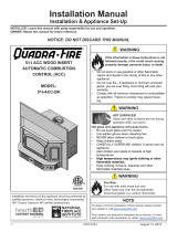
Figure1.1 Necessary installation components.
Note: For manufactured home installations in the USA, the stove must be grounded to the frame of the
home using a # 8 ground wire with approved terminations and star lock washers.
CAUTION: THE STRUCTURAL INTEGRITY OF THE MANUFACTURED HOME FLOOR, WALL, CEILING / ROOF
MUST BE MAINTAINED.
CAUTION: DO NOT INSTALL IN A SLEEPING ROOM.
1.5 INSTALLATION
Installation and operation must follow the information given in this manual.
1.5.1 Installation safety
1. Wherever possible try to have a certified Wood Heating Education & Research Foundation
(WHERF USA) or Wood Energy Technology Transfer (WETT Canada) technician do the
installation.
2. It is important to follow these installation and operation instructions. An improperly
installed or operated stove could result in a fire or other safety hazard or damage to the unit
which would not be covered by the warranty.
Contact local building or fire officials about restrictions and installation requirements in your area.
You should be familiar with the installation and be sure that the work is done in accordance with this
manual. In Canada follow the CSA B365 and the CSA C22.1 installation codes. In the US follow
the ANSI NFPA 70, and 211 installation codes.
TYPICAL MOBILE
HOME INSTALLATION
RAINCAP
FACTORY BUILT CHIMNEY
STORM COLLAR
ROOF FLASHING
SUPPORT/SHIELD
CHIMNEY ADAPTOR
DOUBLE WALL CONNECTOR
DOUBLE WALL 45° ELBOW
OSBURN 1100

/8
3. Proper ventilation is required. If an occupant has respiratory problems, mechanically filtered
ventilation or heat recovery ventilation is recommended.
4. Where lesser clearances are desired, consult your local authority as regulations may vary
regarding the use of clearance reducing devices. Listed wall and floor shields are available to
reduce clearances, and most building codes provide information on materials which may be
used to reduce clearances.
5. Maintain at least the minimum clearances to combustible material as specified in this
manual. Clearances are measured to the nearest part of the stove.
6. Do not connect this unit to any air distribution duct.
7. In any home, we recommend installation of a commonly available listed smoke detector or
alarm. Normal operation of the stove will have no effect on the alarm.
8. Connect the stove only to a lined masonry chimney conforming to building codes for use
with solid fuel or to a listed factory built chimney suitable for use with solid fuel.
9. CAUTION: Do not fill the framed space around the factory-built chimney with insulation or
any other material. Insulation placed in this area could cause adjacent combustibles to
overheat.
10. Minimum chimney size is 6" (152 mm) diameter. Maintain a 12' (3658 mm) minimum
overall height measured from the base of the appliance. Masonry and metal chimneys should
be inspected to check deterioration and to determine if they meet the minimum requirements,
and should be upgraded if necessary. The chimney must extend at least 3' (914 mm) above
the roof and at least 2' (610 mm) above the highest point within an area of 10' (3048 mm) of
the chimney. The Hearth mount unit is to be connected only to a lined masonry chimney and
masonry fireplace, or zero clearance fireplace and chimney conforming to building codes for
use with solid fuel. Do not remove bricks or mortar from the existing fireplace when
installing the Hearth mount unit.

/9
1.5.2 Door overlay installation
In order to complete the assembly of your freestanding Osburn 1100 wood stove, you need to install the
door overlay. See table 1.1.3 below for installation instructions :
1- Position the overlay on the door frame and fix it in place from behind using the 4 screws.
Note: It is not necessary to remove the glass or any other component to install the overlay.
Table 1.1.3 Door overlay installation

/10
1.5.3 Clearances to combustibles
Clearances to any combustibles when measured directly out from the front and up from the top of
the stove, must be a minimum of 48" (1219 mm). The stove should be placed to maintain the
minimum clearances to combustible walls specified for the connector used.
Table 1.1
MINIMUM CLEARANCES TO COMBUSTIBLE MATERIALS
VERTICAL
&
HORIZONTAL
SINGLE
WALL
CONNECTOR
ALCOVE WITH
DOUBLE WALL
CONNECTOR
MIN. WIDTH:
49.5" (1260mm)
MAX. DEPTH:
48" (1220mm)
HEARTH
MOUNT GSW,
SELKIRK,
SIMPSON
DURA-VENT,
AMERI-TEC,.
SECURITY,
DOUBLE
WALL
INDUSTRIAL
CHIMNEY
COMPANY
DOUBLE
WALL
HALF OR FULL
SHIELD
To Unit:
Sidewall A
Backwall B
Corner C
To Connector:
Sidewall D
Backwall E
Corner F
To Unit:
Side Facing G
Mantle H
Hearth J
From Hearth:
Ceiling Height
Fireplace
Opening:
Height K
Width L
Depth M
16" (406 mm)
20" (508 mm)
14" (356 mm)
25" (635 mm)
17.5" (445 mm)
19" (483 mm)
84" (2134 mm)
13" (330 mm)
12.5" (318 mm)
21.5" (546 mm)
10" (254 mm)
84" (2134 mm)
13" (330 mm)
22" (559 mm)
9" (230 mm)
27" (686 mm)
5" (127 mm)
74" (1880 mm)
23" (584 mm)*
23.4" (594 mm)
8" (203 mm)
16.5" (419 mm)
12" (305 mm)
6" (152 mm)
25" (635 mm)
9.5" (241 mm)
12" (305 mm)
84" (2134 mm)
16.5" (419 mm)
8.5" (216 mm)
6" (152 mm)
25" (635 mm)
6" (152 mm)
12" (305 mm)
84" (2134 mm)
*Minimum fireplace opening height includes the use of the "Low Profile Elbow". Standard
elbows require 24" (610 mm) or more clearance height. Minimum fireplace width and depth are
to accommodate a flue liner. The ICC chimney support must protrude into the room by 3"
(75 mm). The other chimney brand supports must protrude into the room by 2.5" (65 mm) as
shown in Figure 4. For horizontal installations, single wall connector must not be less than 18"
(455 mm) from the ceiling.

/11
1.5.3.1 Reduced clearances to combustibles
You may decrease the clearances by installing heat radiation shields between the walls or the ceiling
and the stove. These heat radiation shields must be installed permanently, and can include sheet
metal, a rigid non-combustible sheet or a masonry wall.
Clearances of not less than 1" (25 mm) and not more than 3" (76 mm) between the bottom of the
shield and the floor and not less than 3" (76 mm) between the top of the shield and the ceiling must be
respected to allow vertical air circulation behind the shield. The shield must extend 20" (500 mm)
above the stove top and 18" (450mm) to each side of the stove (see Graphic 1).
Following the installation of such a heat radiation shield, the clearances mentioned on the stove
certification plate may be reduced as stated in the following table.
TYPE OF PROTECTION
Reducing Clearances With
Shielding
Sides and
Rear/Back Top
Sheet metal, a minimum of 0,024" (0,61mm) spaced out
at least 1" (25mm) by non-combustible spacers (see
graphic 2). 67% 50%
Ceramic tiles, or an equivalent non-combustible material
on fire-proof supports spaced out at least 1" (25 mm) by
non-combustible spacers (see graphic 3). 50% 33%
Ceramic tiles, or an equivalent non-combustible material
on fire-proof supports with a minimum of 0,024" (0,61
mm) sheet metal backing spaced out at least 1" (25 mm)
by non-combustible spacers (see graphic 4)
67% 50%
Brick spaced out at least 1" (25 mm) by non-combustible
spacers (see graphic 5) 50% N/A
Brick with a minimum of 0,024" (0,61 mm) sheet metal
backing spaced out at least 1" (25 mm) by non-
combustible spacers (see graphic 6).
67% N/A

/12
Graphic 1
A- Clearance to combustible material with no protection.
B- 500 mm (20 po.) minimum;
C- 25 mm (1 po.) minimum;
D- Between 25 mm (1 po.) and 75 mm (3 po.) ;
E- 75 mm (3 po.) minimum;
F- 450 mm (18 po.) minimum.
1- Wall shielding ;
2- Non-combustible spacers ;
3- Ceiling shielding ;
4- Combustible wall ;
5- Ceiling;
6- Heater (side view) ;
7- Heater (top view).
Graphic 2

/13
A- 25 mm (1 po.) minimum;
1- Combustible wall ;
2- Non-combustible spacer;
3- 0.61 mm (0.024") sheet metal.
Graphic 3
A- 25 mm (1 po.) minimum;
1- Combustible wall;
2- Non-combustible spacer;
3- Fire-proof support;
4- Ceramic tile or equivalent non-combustible material.
_____________________________________________________________________________
Graphic 4
A- 25 mm (1 po.) minimum;
1- Combustible wall;
2- Non-combustible spacer;
3- 0.61 mm (0.024") sheet metal;
4- Fire-proof support;
5- Ceramic tile or equivalent non-combustible material.
Graphic 5
A- 25 mm (1 po.) minimum;


/16
Figure 1.4
1.5.5. Installation instructions
1. Inspect the fireplace according to the safety information and fireplace requirements and
have it cleaned and/or upgraded as necessary.
2. If the installation of the unit renders the existing damper control inaccessible, it will be
necessary to either secure the damper wide open, or remove it entirely. An inaccessible
damper which may fall shut later could cause smoke to enter the room. This would be a
nuisance as well as a potential health hazard. Figure 1.4 illustrates a typical fireplace
installation.
3. Install the liner in the chimney.
4. Seal the space between the liner and the chimney.

/17
1.6 Chimney System
1.6.1 Definitions
For clarity, the following definitions should be used with respect to these instructions:
A chimney system consists of the connector off the top of the stove, and a chimney, which joins to the
connector and terminates outside the building envelope.
A chimney can be a masonry chimney (of masonry construction with an inside liner), or a factory
built chimney.
A factory built chimney can be a double walled chimney (two concentric pipes with insulation
sometimes referred to as an insulated solid pack, or an air cooled chimney (three concentric pipes,
with insulation between the first and second pipes, and air between the second and third pipes).
A single walled connector is a single pipe.
A double walled connector has two concentric pipes, no insulation, and is an air cooled connector.
1.6.2 Components
NOTE: All connector and manufactured chimney components must be LISTED COMPONENTS.
Masonry Chimneys must be Code Complying, and have a listed solid fuel burning liner (of stainless
steel or clay refractory construction).
1.6.2.1 Factory Built Chimney System
The following are the generic components required for a factory built chimney system for
residential installations:
Chimney – in the USA use a 6” diameter (152 mm) listed UL 103 HT chimney system and
components
Chimney – in Canada use 6” diameter (152 mm) listed ULC S629 chimney system and components
MANUFACTURED (MOBILE) HOME CHIMNEY SYSTEM
In addition to the requirements of section 1.6.2 the following components are required for
manufactured (mobile) home installations:
A spark arrestor must be employed with the rain cap
Double walled connectors must be used instead of single walled connectors
For manufactured (mobile) home installations in the USA only and where the chimney system has
employed a solid pack chimney, a vented roof flashing must also be used.

/18
1.6.2.2 Residential Close Clearances Chimney System
In addition to the requirements of section 1.6.2.1 the following components are required for
residential close clearances installations:
Double walled connectors must be used instead of single walled connectors
1.6.3 General Installation Requirements
CAUTION: DO NOT FILL ANY FRAMED SPACE AROUND THE FACTORY-BUILT CHIMNEY WITH
INSULATION OR ANY OTHER MATERIAL. INSULATION PLACED IN THIS AREA COULD CAUSE ADJACENT
COMBUSTIBLES TO OVERHEAT.
DO NOT USE MAKESHIFT COMPROMISES DURING INSTALLATION AS THEY MAY BE SAFETY HAZARDS,
AND A FIRE COULD RESULT.
DO NOT CONNECT THIS UNIT TO A CHIMNEY SYSTEM SERVING ANOTHER APPLIANCE.
DO NOT CUT RAFTERS OR CEILING JOISTS WITHOUT FIRST CONSULTING A BUILDING OFFICIAL TO
ENSURE STRUCTURAL INTEGRITY IS NOT COMPROMISED.
1.6.3.1 Connectors
The minimum connector diameter is 6" (152 mm). A minimum connector length of 4 ft (1.22 m) is
recommended for best results. Restrictions to stack gas flow (such as using more than two 90o elbows)
should be avoided and any horizontal runs should be kept to a minimum length, especially with short
chimneys. The connector pipe, which joins the unit to the chimney, may be of either single or double
walled construction. Connector pipe should be a minimum of 24-gauge steel.
The connector pipe itself must not pass through any combustibles, nor may it pass through non-
combustibles and into a concealed space (such as an attic, roof space, or closet). If passing through a wall,
ceiling, or into a masonry chimney, use either chimney components listed for that specific use, or means
acceptable to local authorities having jurisdiction over the installation.
Install sections of single wall or double wall connector between the stove and the chimney. Secure all
connector pipe joints with a minimum of three sheet metal screws. All connector and factory built chimney
pipes must be installed with the male or crimped end down to prevent creosote dripping outside the joints.
If non-telescopic sections are to be used, they must be cut to length, allowing for overlap. Use three (3)
screws to attach the connector section to the flue collar of the stove. Listed double walled connectors
should be installed in accordance with the vent manufacturer’s installation instructions.

/