Page is loading ...

1
Hearth & Home Technologies • Heat-Zone® Gas Air Duct Kit • 659-900 Rev. S • 2/20
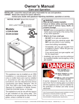
Possible Air Duct Runs/Locations
Approvals
The exible duct in this Heat-Zone® Gas air duct kit is
manufactured and marked to the requirements of UL-181,
Class I air duct.
Introduction
The Heat-Zone-Gas accessory kit conveys warm air from
the replace through air duct(s) to remote locations in the
same room or other rooms of the building. See Figure 1.
One or two Heat-Zone® Gas kits can be installed on the
replace.
Heat-Zone® Gas Air Duct Kit
- Installation & Operation Instructions -
DESCRIPTION SERVICE PART NO.
20 ft. Length of 6 in. Insulated
Round Duct 659-200
Fan Housing Assembly 659-001A
Junction Box 659-122
Variable Wall Rheostat BC10
Air Register 659-150
Register Adaptor Frame-Thick 695-125
Fireplace Duct Collar 659-125
Duct Adaptor (Round to Oval) 659-129
If any parts are missing or damaged, contact your Dealer before
starting installation. DO NOT install a damaged kit. Be sure to
also reference the replace Installers Guide.
Preliminary Preparation
Contents of kit:
CEILING REGISTER
CEILING REGISTER
WALL REGISTER
TWO DUCT
KITS
INSTALLED
FLOOR REGISTER
Figure 1
18 in.
6-3/4 in.
MINIMUM SPACE
REQUIRED FOR
90 DEGREE BEND

Hearth & Home Technologies • Heat-Zone® Gas Air Duct Kit • 659-900 Rev. S • 2/202
This kit is tested and safe when installed in accordance with
this installation manual. It is your responsibility to read all
instructions before starting installation and to follow these
instructions carefully during installation.
Installation of this kit MUST be performed by a qualied
service technician.
The Heat-Zone-Gas kit is carefully engineered and must
be installed only as specied. If you modify it or any of its
components you will void the warranty, and you may possibly
cause a re hazard. Installation must be done according to
applicable local, state, provincial, and/or national codes.
CAUTION! All wiring should be done by a qualied electri-
cian and shall be in compliance with local codes and with
the National Electric Code ANSI/NFPA No. 70-current (In
the United States), or with the current CSC22.1 Canadian
Electric Code (in Canada).
Installation
3. Determine the location for the air register/fan housing
assembly. Cut a 5 in. x 13-5/8 in. (127 mm x 346 mm)
hole between framing members (wall studs or oor
joists). The fan and electrical connections must be
accessible for servicing per local code requirements.
4. Mount and secure the fan housing assembly to framing
members so the front surface is 1/4 in. (6 mm) below
the nished wall or oor surface. Use the adjustable
mounting brackets and screws provided in the kit. See
Figure 3 and Figure 4.
Note: The brackets can be rotated 180º and mounted to
the back side of the 2 x 4 if necessary.
ADJUSTABLE
MOUNTING
BRACKETS
FINISHED SURFACE
FRONT OF FAN
HOUSING
1/4 IN.
(6 MM)
2 IN. X 6 IN. WALL
FAN HOUSING
1/2 IN.
(13 MM)
FINISHED SURFACE
14 IN.
4-1/2 IN.
FAN HOUSING
2 IN. X 4 IN. WALL
ADJUSTABLE
MOUNTING
BRACKETS
Figure 4
Note: If the fan housing is installed in a 2 x 4 wall, the front
of the housing will protrude approximately 1/2 in. (13 mm)
out of the wall. See Figure 3.
Figure 3
KNOCKOUT
DUCT COLLAR
Figure 2.
Pre-Installation
1. Plan the location of the replace and the warm air duct
run(s). See Figure 1 for potential installation options.
Venting Guidelines
MAXIMUM Duct Run = 20 ft. (6.1 m) for useful heat output.
Insulated duct included with kit will not lose signicant heat.
MINIMUM Duct Run = None: For runs out from the replace
to adjacent room OR down to the room below.
MINIMUM Duct Run = 31 in. (787 mm) top of replace to
room above.
• Maintain smooth turns in duct to ensure maximum heat
output.
• If using optional non-insulated pipe, as described in
Step 6, heat loss will occur and shorter duct runs will
yield higher heat output.
1. Remove the knockout or cover plate from the side or
top of the appliance and discard it. See Figure 2.
2. Center the duct collar around the exposed hole and
attach it to the replace with three screws.
Note: Do this before nal positioning of the appliance.

3
Hearth & Home Technologies • Heat-Zone® Gas Air Duct Kit • 659-900 Rev. S • 2/20
Operation
1. Start the replace per instructions and allow it to
warm up.
2. If using the included rheostat, turn the wall Rheostat
"ON" and adjust the variable speed based upon desired
air ow at the air duct register.
3. If using the IFT RC400 remote, select the fan speed
icon from the menu and adjust the speed based upon
the desired air ow at the air duct register.
Maintenance
Service and maintain the gas replace per instructions.
Keep the air register(s) clean and free of any blockage.
Fan Housing
Round to Oval Adapter
6 in. Insulated
Round Air Duct
Figure 5
5. Install the air duct run. Note: Fold outer poly layer of
exible duct back to maintain clearance to combustibles
on the replace. Secure liner to the collar with clamp
provided.
6. Insulated Round Air Duct: Attach the 6" round air duct
(supplied in the kit) to the replace collar with sheet
metal screws and run the duct to the fan housing. At-
tach the round-to-oval adapter to the fan housing and
the air duct to the adapter. See Figure 5.
Optional Non-Insulated Oval Air Duct:
Note: 6 in. metal oval air duct is NOT provided with this
kit but can be purchased from an HVAC supplier.
Attach the round-to-oval adapter to the replace starting
collar with sheet metal screws and a 6" oval duct to the
adapter. Complete the duct run and attach the oval duct
to the fan housing.
Round And Oval Duct: A combination of 6 in. round
and 6 in. oval air duct can be used in the duct run. Oval
duct components must be purchased from an HVAC
supplier.
7. Support duct at intervals of no greater than four feet,
with no more than 1/2 in. sag between supports as
required by local code. Note: Secure the duct so that
clearance to the replace outer wrap is maintained.
Tape all seams with aluminum tape (1-1/4 in. minimum
width, or as specied by local codes).
8. Install the variable speed (with "OFF" setting) wall
Rheostat in a convenient location. This switch will
control the Heat-Zone® GAS fan operation.
9. Wire 110 VAC service TO the wall Rheostat and FROM
the wall Rheostat to the fan junction box. Use wire nuts
to secure the 110 VAC service wires to the hot and
neutral fan wires and screw the 110 VAC ground wire
to the fan junction box. See Wiring Diagram - Figure 6.
10. Screw the fan junction box to the fan housing.
11. Screw the register adapter frame and the air register
to the fan housing.
12. Complete the replace installation per instructions.
13. Wire the Heat-Zone-Gas blower assembly from the
blower junction box to the appliance.
Note: If the IFT-ACM fan port not used for an appliance
fan, it is capable of accommodating and operating two
Heat-Zone-Gas kits.
14. Using a standard 120 volt plug-in, wire the ends of the
wires from the blower junction box (or junction boxes if
two Heat-Zone-Gas kits will be installed) to the plug-in
inside the appliance. See Figure 7.
15. Attach the plug-in to the ACM fan outlet.
16. Re-pair the remote to the appliance.
17. Complete the replace installation per the instructions
included with the replace.
Electrical Connection Using Included Rheostat
Electrical Connection to HHT IntelliFire
Touch® Controls

Hearth & Home Technologies • Heat-Zone® Gas Air Duct Kit • 659-900 Rev. S • 2/204
Ground Screw Hole
Ground
Fan
Black
White
Ground
Fan
Junction Box
Rheostat
Rheostat
Junction Box
Black Hot
White Neutral
Copper Ground
Figure 6 Rheostat Control
Please contact your Hearth & Home Technologies
dealer with any questions or concerns.
For the location of your nearest Hearth & Home
Technologies dealer, please visit www.hearthnhome.com.
Hearth & Home Technologies
7571 215th Street West, Lakeville, MN 55044
www.hearthnhome.com
RF MODULE
IFT-RC400
REMOTE
CONTROL
OPTIONAL HEAT-ZONE-GAS KIT
Optional HEAT-ZONE-GAS kit shown wired
to IFT-ACM. Appliance must be re-paired if
adding a HEAT-ZONE-GAS or HEAT-OUT-GAS
to the IFT-ACM.
Wiring MUST be performed by a certified
electrician.
Thick line denotes wiring supplied by electrician.
WIRE PLUG ASSEMBLY
26D0619
Figure 7 IntelliFire Touch Controls
/