
Design Guide with
Installation
Instructions
Wine Reserve
ZDWT240
Qnd
Beverage Center
ZDBT240
monogram.com

Safetg Information
BEFORE YOU BEGIN:
Read these instructions completely and carefully.
IMPORTANT - Savetheseinstructions
for local inspector's use.
IM PORTANT - Observeallgoverningcodes
and ordinances.
Note to Installer - Besure to leave these
instructions with the Consumer.
Note to Consumer - Keepthese instructions with
your Owner's Manual for future reference.
WARN ING - Thisappliancemust be properly
grounded.See "Grounding",page/4.
AVERTISSEMENT-
Cet appareil doit @trecorrectement mise 5 la terre.
Consulter <<Mise 5 la terre>>, page/4.
Ifyou receiveda damaged winereserveorbeverage
center,you shouldimmediatelycontactyourdealer
or builder.
Skill Level - Installation requires basic mechanical skills.
Proper installation isthe responsibility of the installer.
Product failure due to improper installation
is not covered under the GEAppliance Warranty.
WARNINGS:
• Usethis appliance only for its intended purpose.
• Immediately repair or replace electrical service cords
that become frayed or damaged.
• Unplug the unit before cleaning or making repairs.
• Repairs should be made by a qualified service
technician.
AVERTISSEMENT:
• IIne faut utiliser cet appareil que pour I'usage pour
lequel il a @t@construit.
• IIfaut r@parerou remplacer imm@diatement tout
cordon d'alimentation @lectriqueeffiloch@ou
endommag@.
• D@brancherle bar ou le r@frig@rateura vin avant
le nettoyage ou toute intervention.
• Lesr6parations doivent @trefaites par un technicien
qualifi@.
For Monogram local service in gour area,
call 1.800.444.1845
For Monogram service in Canada, call
1.800.561.3344
For Monogram Parts and Accessories, call
1.800.626.2002.
www. monogram.com
CONTENTS
Design Guide
The Installation Space .............................3
Product Clearances ...................................3
Installation Instructions
Tools, Hardware ..........................................4
Grounding the Product ............................4
Staining Wood Drawer Fronts..............4
Step 1,Remove Packaging ....................4
Step 2, Leveling ...........................................5
Step 3, Connect Power ............................5
Step/4, Slide Product into Cutout ........5
Step 5, Change the Toekick ...................5
Step 6, SetTemperature Controls ......5

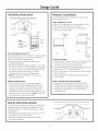
Design Guide
THE INSTALLATION SPACE
_..l-- 23-3/4"
I_ / _,
Handleand
handle i
standoffdepth
is 1-3/4"
ii.......23-3/4".....
The cutout depth should be 24"
The cutout dimensions shown allow for a full door swing
and access to the pull-out racks when installed as a
built-in in standard 24" deep cabinets.
• The wine reserve and beverage center can be
installed freestanding.
• If installing between frumeless cabinets, u 1/2" wide
filler strip or side panel may be needed on hinge side.
The filler strip will act as a spacer between the case
and adjacent cabinet door swing. The width
of the opening must include the filler panels.
NOTE:The door should protrude 1" beuond the
surrounding cabinets.
Additional Specifications
• A 120volt 60Hz., 15 or 20 amp power supply is
required. An individual properlu grounded branch
circuit or circuit breaker is recommended. Install a
properlu grounded 3-prong electrical receptacle
recessed into the back wall as shown. Electrical must
be located on rear wall as shown. NOTE:GFI(ground
fault interrupter)is not recommended.
PRODUCT CLEARANCES
Thewine reserve and beverage center isfactory set
for a 110° door swing.
When installed in a corner:
• Allow 4" min. clearance on the hinge side for the 90°
door swing and to allow racks to slide out.
• Allow 10" minimum clearance on the hinge side
for a full 110°door swing.
10"Minimum
to Wall
!,
I
t.
_t
90° DoorSwin(
-5/8"
23-5/8"
90°.
4"Minimum
toWall
Choose the location:
• These products may be closed in on the top and three
sides as long as the front is unobstructed for air
circulation and proper access to the door.
• Donot install these products where the temperature will
go below 55°F (13°C)or above 90°F (32°C).
• Do not install where it will be subject to direct sunlight,
heat or moisture.
• These products are not designed to be stacked one
over the other.
Black or Stainless Steel Toekick Options
• These products are shipped with a black toekick
installed. An optional stainless steel toekick is also
supplied with each product. For shipping purposes,
the stainless steel toekick issecured to the back
or inside the unit.
SIDE-BY-SIDE INSTALLATIONS
Increase storage capacity by installing two Monogram
beverage centers or wine reserves together. Or,for a
complete refreshment center, install any two of these
units together.
• Aside-by-side installation requires at least a 47-1/2"
wide opening. No trim kits required.
• Products must operate from separate, properly
grounded receptacles.
34-1

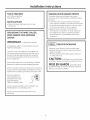
Installation Instructions
TOOLS REQUIRED
• #2 Phillips screwdriver
• Adjustable wrench
PARTS SUPPLIED
• Optional stainless steel toekick with screws
and spacers
GROUNDING THE WINE CHILLER,
WINE RESERVE AND BEVERAGE
CENTER
IMPORTANT - Pleasereadcarefully.
FORPERSONALSAFETY,THISAPPLIANCEMUSTBE
PROPERLYGROUNDED.
The power cord of this appliance isequipped with
a three-prong (grounding) plug which mates with a
standard three-prong (grounding) wall receptacle
to minimize the possibility of electric shock hazard
from this appliance.
Have the wall outlet and circuit checked by a qualified
electricianto make surethe outletisproperlygrounded.
Where a standard 2-prong wall outlet isencountered, it
is your personal responsibility and obligation to have it
replaced with a properly grounded ]-prong wall outlet.
DO NOT, UNDER ANY
CIRCUMSTANCES, CUT
OR REMOVE THE THIRD
(GROUND) PRONG
FROiVlTHE POWER CORD.
DO NOT USEAN ADAPTER PLUG TO CONNECT THE
REFRIGERATORTO A 2-PRONG OUTLET.
DO NOT USEAN EXTENSION CORD WITH THIS
APPLIANCE.
STAINING WOOD DRAWER FRONTS
The drawer fronts are unfinished cherry wood.
During use, oil from hands may accumulate and stain
the wood.
• The drawer fronts may be stained and sealed to
match adjacent cabinetry. The tinted glass will make
the stained wood appear darker. A true color match
can be seen only when the door is opened.
• Apply the stain and sealer according to the
manufacturer's instructions. To avoid unpleasant
odor, keep the door open to ventilate and allow
the stain/sealer to dry completely before using
the product.
ISTEP 11 REMOVE PACKAGING
• Remove corner blocks and foam drawer stops.
• Remove all packing material, tape and protective
plastic coverings.
• Remove stainless steel toekick taped to the back
or inside of the unit.
CAUTION: Small objects area chokehazard
for children. Removeand discard any parts not used.
MISE EN GARDE :Lespetitsobjets
peuvent _trangler lesenfants. IIfautjeter toutes les
pi_ces qui ne sont pas utilis_es.

Installation Instructions
I STEP 2 I LEVEL
• Usean adjustable wrench to turn the leveling legs and
raise or lower the product.
• Adjust carefully; the product should be level and plumb
with cabinetry, and should align with adjacent toekick
height.
\
TurnRightto Lower
TurnLeftto Raise
I STEP 3 I CONNECT POWER
• Connect power cord plug to a properly grounded
receptacle.
• Check to make sure power is on by opening the door
to see if interior light turns on.
I STEP 4 I SLIDE PRODUCT INTO
THE CUTOUT
WARNING: Do not apply pressure or push
against the glass door when moving or installing these
products. Pressure against the glass door will cause
damage.
AVERTISSEMENT: Nepoussez
jamais et ne mettezjamais de pression sur la porte
en verre quand vous d_placez ou installez ces produits.
Toute pression sur le verre occasionnera des
dommages,
• Carefullyslidetheunitintotheopening,Be careful
nottoentanglepower cord.
• Make certainthatthedoorprotrudes1"beyond
thesurroundingcabinets,
• Checkagaintobesuretheunitislevel.
I STEP 5 I CHANGE THE TOEKICK
• The stainless steel toekick is secured to the back
of the product or inside.
• Thetoekick has a
cutout on the left
and right sides.
Remove
the plug on
the left
side and @
reinstall MoveFill
on the " Plugto
RightSide
right side.
If you
choose to ",
install the _.
stainless steel toekick,
reinstall the plug on the right side
of that toekick.
• Installoriginalscrewsandspacersorscrewsand
spacers supplied with the stainless steel toekick. Install
screws through the spacer standoff, toekick and into
the base as shown.
I STEP 61 SET TEMPERATURE
CONTROLS
• Thetemperature controls are preset, Refer to the
Owner's Manual for more information. Allow 2/4hours
for temperature to stabilize.

Notes

Notes

Note: While performing installations described in this book,
safety glasses or goggles should be worn.
For Monogram ®local service in your area, call
1.800.444.1845.
Note: Product improvement is a continuing endeavor at
Genera] Electric. Therefore, materials, appearance and
specifications are subject to change without notice.
Pub. No. 31-46065-1
Part No. 197D6374PO01
09-07 JR
Printed in SIovenia
GE Consumer & Industrial
Appliances
General Electric Compan U
Louisville, KY 40225
ge.com
-
 1
1
-
 2
2
-
 3
3
-
 4
4
-
 5
5
-
 6
6
-
 7
7
-
 8
8


GE ZDWT240PCBS Installation guide
- Type
- Installation guide
- This manual is also suitable for
Ask a question and I''ll find the answer in the document
Finding information in a document is now easier with AI
Related papers
-
GE ZDBT240 Installation guide
-
-
-
-
-
-
GE ZDWR240NBS Installation guide
-
-
GE PCR06WATSS Owner's Manual and Installation Instructions
-
Other documents
-
Monogram ZIBI240 Installation guide
-
 GE Monogram ZDBI240HII Installation guide
-
-
Monogram ZDBR240NBS Installation guide
-
-
-
 GE Monogram Beverage Dispenser ZDWG240 User manual
-
 GE Appliances ZIP360NZ Installation guide
-
 GE Monogram ZIRS360NBRH Installation guide
-


