Page is loading ...

Industrial
Air/Water Hose Reel
Item #8025291
Read the following precautions and instructions before you assemble or use.
Failure to comply with these instructions could result in personal injury or property
damage. Keep these instructions in a convenient location for future reference.

Specifications
This hose reel includes a spring drive drum for automatic
rewind, and a locking ratchet to maintain the desired length of
hose in use.
Safety Precautions
1. Make sure incoming line pressure does not exceed rated
operating pressure for your hose reel.
2. Use proper eye protection when assembling and using the hose reel.
3. Assemble the hose reel on a clean workbench.
4. Use soap and water when checking for leaks.
5. Keep children away from the work area.
Warning: Exposure of skin directly to pressurized air or fluid could result in severe bodily injury.
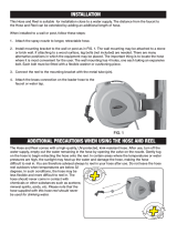
Installation of Hose Reel
NOTE: For overhead ceiling mounting: install reels at least 10 feet above the floor. You will
need to purchase appropriate hardware for mounting you new reel.
1. The reel base has four 1/2" (12.7 mm) drilled holes for mounting on a suitable flat surface.
2. The reel is supplied with a hose guide roller bracket. The bracket position may be changed
depending on the reel mounting position. Figure 2 shows "Typical Mounting Positions". If
bracket position needs to be changed, do the following:
a) Pull out some hose and let reel latch
b) Remove the bolts that attach the guide roller bracket to the support post.
c) Rotate guide roller bracket to correct position, replace bolts and tighten
3. Using the four holes in the base, mount the reel in the desired location. Be sure to use
appropriate hardware and tighten securely.
4. Apply teflon tape or pipe sealant to supply line threads, attach to reel inlet and tighten. The
other end of incoming line can now be connected to desired supply source.
Wall Floor Ceiling

5. Apply teflon tape or pipe sealant to outlet fitting on reel hose, then attach to desired tool, or
nozzle. Check connection for leakage, also check hose reel for correct operation. (Details see
Operation section.)
6. If hose stopper adjustment is required, pull hose from reel and allow to latch at desired length.
Loosen stopper bolts and slide stopper to a position close to the hose guide. Tighten stopper
bolts, and unlatch the reel.
Installation of Hose
1. Securely stabilize the reel.
2. Facing the swivel fitting side of reel: turn the drum clockwise by hand, until the rewind spring
is tight, and drum has latched. As an extra precaution while installing new hose, secure drum
in the latched position.
3. Insert end of the hose through guide roller bracket, and feed through the opening in the drum
flange.
4. Use teflon tape or pipe sealant on hose fitting threads, screw fitting into swivel and tighten.
Note: to avoid damage to the swivel, use a wrench to support the swivel fitting while
tightening the hose.
5. Attach hose stopper on the other end of hose, near the outlet fitting.
6. Carefully release drum latch, and slowly allow hose to wind onto the reel.
Note: Final spring tension adjustment is accomplished by adding wraps of hose around the drum
(to increase tension) or taking or wraps of hose (to decrease tension). Refer to: Adjustment of
Spring Tension.
Operation
1. Check reel for correct operation by slowly pulling out the hose. A "clicking" noise will be
heard every half revolution of the drum.
2. To latch the reel, pull out the hose and allow it to retract after hearing the first, second, or third
"click".
3. To unlatch, slowly pull out the hose until the "clicking" noise stops, then let the hose retract
until the hose stop rests against the hose guide. NOTE: to avoid damage to the reel, always
hold onto the hose while it is rewinding.
4. Periodically check the hose condition for wear or damage, and check the swivel fitting for
leakage. Replace any worn, damaged, or leaking parts.

Adjustment of Spring Tension
1. Pull out approximately 6 ft (2 meters) of hose and allow the drum to latch.
2. Remove hose stopper from hose, and feed hose back through guide.
3. Wrap the pulled hose one time around the drum to increase tension or unwrap hose one time
from drum to decrease tension.
4. Re-insert hose through guide, and install stopper onto hose end.
5. Unlatch the drum and check tension. Pull hose from reel, and adjust stopped position if
necessary.
Replacement of Swivel Seal
1. Turn off and disconnect supply line from swivel inlet.
2. Remove swivel assembly from reel axle.
3. Remove circlip from swivel , and take apart. Note: You may want to remove swivel from reel
hose end, but this is not necessary unless a new swivel is being installed.
4. Replace the seals and reassemble swivel.
5. Use teflon type or thread sealant on swivel thread fitting, and reconnect the swivel thread
fitting with axle.
6. Re-connect inlet supply line.
Replacement of Hose
1. Turn off supply to reel.
2. Pull out all the old hose and lock the reel in this position. Caution: make sure reel drum is
securely locked and cannot rotate back.
3. Remove two hose clamps from hose.
4. Carefully disconnect hose from swivel joint on side of reel, or male fitting in axle center and
remove old hose.
5. Feed new hose through guide and opening in drum, and connect to swivel. Re-install two hose
clamps, on inside and outside of drum flange. Install stopper on other end of hose in the same
position as before.
6. Carefully release the drum latch, and slowly allow the hose to wind onto the reel. Note: final
spring adjustment is accomplished by adding or removing wraps of hose around the drum. For
details, see Spring Tension Adjustment.
Spring Canister Warning
If the rewind spring fails for any reason, the manufacturer strongly recommends the replacement
of the spring canister be carried out by a professional mechanic for safety reasons.

Parts List
Part No. Description
1 Spring
2 Drum
3 Drum
4 Base
5 Arm
6 Swivel (including swivel part, rigid part, 2 o-rings and label)
7 Hose
8 Guard H
9 Assembly Hub Bearing
10 Bolt
11 Locking Cam
12 Dog Spring
13 Axle
14 Washer
15 Nut
16 Bolt
17 Nut
18 Clamp
19 Clamp
20 Bolt
21 Washer, Bolt
22 Nut
23 Washer
24 Bolt
25 Keps Nut
26 Lock Nut
27 Assembly Roller Bracket
28 Ball stop
29 Locking ring
30 Spacer washer
31 Retaining ring
32 Bolt
33 Lock washer
34 Set screw
35 Spacer washer
36 Nut
37 Spacer washer
38 Bolt
/