
Installation Guide
Vibracoustic Bath with Heated Surface
Retain serial number for reference:
Conserver le numéro de série pour référence:
Guarde el número de serie para referencia:_____________________
Français, page ″Français-1″
Español, página ″Español-1″
1212240-2-B

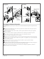
IMPORTANT INSTRUCTIONS
WARNING: When using electrical products, basic precautions should always be followed,
including the following:
WARNING: Risk of electric shock. Connect only to a circuit protected by a Ground-Fault
Circuit-Interrupter (GFCI)*. Grounding is required. The unit should be installed and grounded by a
qualified service representative.
WARNING: Risk of electric shock. A qualified electrician should route all electrical wiring.
WARNING: Risk of electric shock. Disconnect power before servicing.
WARNING: Risk of electric shock. Do not operate electrical powered auxiliary devices near water.
WARNING: Risk of property damage. Building materials and wiring should be routed away from
the heat-producing components of the bath.
WARNING: Risk of injury or property damage. Please read all instructions thoroughly before
beginning installation.
NOTICE: Follow all plumbing, electrical, and building codes.
*Outside North America, this device may be known as a Residual Current Device (RCD).
Product Information
Electrical Requirements
WARNING: Risk of burns, fire, electric shock, or injury. Do not operate the heater if the power
supply cord is damaged. For proper guidance to have this product repaired, please call:
1-800-4KOHLER from within the USA or Canada, or 001-800-456-4537 from within Mexico.
This installation must have a Class A Ground-Fault Circuit-Interrupter (GFCI)*. The GFCI protects against
line-to-ground shock hazard. Use a 120 V, 15 A, 60 Hz dedicated service for the bath.
Two 120 V, 15 A (240 V, 15 A in Latin America) GFCI electrical outlets are required. One outlet should be
located within the stud framing and within 24″ (610 mm) of the control amplifier. The other outlet must be
within 24″ (610 mm) of the junction box mounted to the control board at the lumber end of the bath. Both
outlets may share the same electrical service, but no other load should be on this circuit.
*Outside North America, this device may be known as a Residual Current Device (RCD).
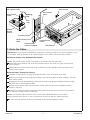
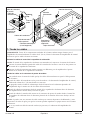
Factory-Assembled Features
Factory installed components include heated surface with power supply cord, transducers, and
chromatherapy lights (if equipped). Other than power wiring and plumbing, no assembly is needed.
1212240-2-B 2 Kohler Co.

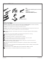
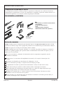
Tools and Materials
Before You Begin
NOTICE: Adequate floor support must be provided. Note the model number on the back of the bath,
then visit the product page at www.kohler.com for additional information.
NOTICE: Do not support the load weight of the bath by the rim.
NOTICE: Verify adequate support if installing a rim- or deck-mount faucet. Large faucets that may be
inadvertently used as a means of support are not safe for this installation.
Read these instructions and determine the locations of all required components before beginning
installation.
Provide access to the control amplifier and control board connections for servicing.
This bath is designed for drop-in or island installation.
For under-mount installation, an under-mount kit is required.
The control amplifier may be installed remotely and includes a 25’ (7.6 m) cable.
Use conduit to route electrical wires from the circuit breaker.
Choose the location for a battery operated auxiliary audio device, if used. Do not locate AC
powered devices within reach of the bath.
Carefully plan moving the bath into the installation area. This bath will not easily fit through
doorways.
Inspect the bath and components before beginning installation. If there is damage, do not install the
bath; contact your dealer.
Install this bath on a level subfloor. Shims may be needed if the subfloor is uneven.
This bath conforms to CSA B45.5/IAPMO Z124. All dimensions are nominal.
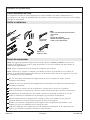
• Conventional woodworking tools and materials
• 2x4s
• Drop cloth
• Mortar cement (Optional)
• Construction adhesive (Optional)
Plus:
#1
Tin Snips
100% Silicone Sealant
#2
Kohler Co. 3 1212240-2-B

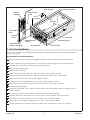
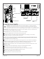
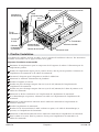
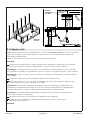
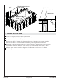
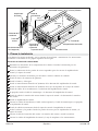
1. Plan the Installation
For best results, follow the installation sequence below. Detailed instructions are found on the following
pages of this guide.
Recommended Installation Sequence
Determine the locations for the bath components. Refer to the illustration for preferred locations.
Plan the required access panel locations for servicing the control amplifier and the control board.
Construct the framing for the bath and install the rough deck.
Route plumbing supply lines.
Install the bath and drain.
Install an electrical outlet within 24″ (610 mm) of the control amplifier location.
Install an electrical outlet within 24″ (610 mm) of the junction box on the control board.
Route the transducer wires to the control amplifier location.
If equipped, route the chromatherapy cable to the control amplifier location.
Route the user interface cable from the control board to the user interface location.
Install the control amplifier.
Connect the transducer wires, optional auxiliary cable, and chromatherapy cable (if equipped) to the
control amplifier.
Route the inter-connect cable from the control board to the control amplifier.
Finish the deck and walls. Install access panels for the control amplifier and control board.
Connect the user interface cable to the user interface, and install the interface.
Connect the control amplifier and junction box cables to the electrical outlets.
Test the functionality of all bath components. Refer to the ″Homeowners Guide″ for operation.
Transducer
User Interface
Control
Amplifier
Heated Surface
6" (152 mm) Maximum
Transducer
Wires
Access
Panel
Control Board
Access Panel
Inter-Connect
Cable
10"
(254 mm)
24"
(610 mm)
Heated Surface
Control
Chromatherapy
Cable (If Equipped)
1212240-2-B 4 Kohler Co.

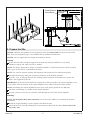
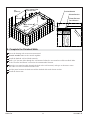
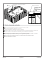
2. Prepare the Site
NOTICE: Measure your product for site preparation. Note the model number on the back side of the
bath, then visit the product page at www.kohler.com for additional information.
NOTICE: Do not support the load weight of the bath by the rim.
Framing
Ensure the floor offers adequate support for the bath and verify the subfloor is level. Install
additional support and adjust for level as needed.
NOTE: This bath is designed for drop-in or island installation. If a deck-mount faucet will be installed,
plan a space on the deck to accommodate the faucet.
NOTE: Use wood or concrete framing. Wood framing will provide the best vibracoustic quality.
Construct the framing, taking into account the thickness of the finished materials.
Provide a 1/16″ (2 mm) gap between the framing and the underside of the bath rim to ensure the
bath is not supported by the rim.
IMPORTANT! Several of the included bath components will be powered by the control amplifier via 25’
(7.6 m) cables. Plan the location of the control amplifier so the cables will reach without tension.
NOTE: If installing the control amplifier between studs, stud spacing should be 16″ (406 mm).
Construct stud framing or a pocket for the control amplifier.
Provide a means to route the user interface cable through the wall to the control amplifier.
Plumbing
NOTE: For through-the-floor drain installation: cut a hole in the subfloor to accommodate the drain
connections.
Install the rough plumbing. Cap the supplies and check for leaks.
Attach the drain to the bath according to the instructions packed with the drain. Do not connect the
trap at this time.
Drain Cutout
1/16" (2 mm)
Minimum
Water-Resistant
Deck Material
Kohler Co. 5 1212240-2-B

3. Install the Bath
NOTICE: Ensure the subfloor is level before proceeding. Use shims as needed.
Secure the bath using one of the following two methods.
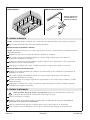
Cement or Mortar Bed Method
NOTICE: Do not use gypsum cement or drywall compound, as these materials will not provide a durable
bond.
Spread a 2″ (51 mm) layer of cement or mortar bed on the subfloor.
With help, carefully lower the bath into place. Take precaution to avoid damaging the components
mounted to the bath.
Press the bath into the cement or mortar bed, leaving a 1/16″ (2 mm) gap between the deck and the
underside of the rim.
Verify the bath is level. Reposition or shim as needed.
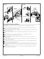
Construction Adhesive Method
Apply a generous amount of high-quality construction adhesive to the bottom of the support blocks.
With help, carefully lower the bath into place. Take precaution to avoid damaging the components
mounted to the bath.
Press the bath onto the subfloor, leaving a 1/16″ (2 mm) gap between the deck and the underside of
the rim.
Verify the bath is level and resting on all support blocks. Reposition or shim as needed.
4. Install the Plumbing
CAUTION: Risk of property damage. Ensure a watertight seal on all bath drain connections to
prevent water leakage.
Connect the drain to the trap.
Install the faucet valve according to the faucet manufacturer’s instructions. Do not install the faucet
trim at this time.
Open the hot and cold water supplies. Check all connections for leaks.
Fill the bath to the overflow and check the drain connections for leaks.
Mortar Cement
Construction Adhesive
Apply construction
adhesive to the
support blocks.
1212240-2-B 6 Kohler Co.

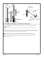
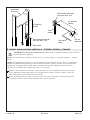
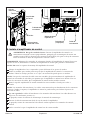
5. Install Electrical Outlets – United States and Canada
WARNING: Risk of electric shock. Disconnect the power before performing the following
procedures.
NOTE: For installations in Latin America, go to the ″Make Electrical Connections – Latin America″
section.
NOTICE: The control amplifier and junction box are each equipped with a cord and plug. A qualified
electrician must install two GFCI- or RCD-protected, 120 V, 15 A grounded outlets. Both outlets may share
the same electrical service, but no other load should be on this circuit.
Install a 120 V, 15 A grounded outlet within the wall framing and within 24″ (610 mm) of the
planned control amplifier location. Route the wires through conduit for this outlet installation.
Install a 120 V, 15 A grounded outlet near the control board end of the bath and within 24″ (610
mm) of the junction box.
Control
Amplifier
24" (610 mm)
Maximum
Conduit
Junction
Box
24" (610 mm)
Maximum
120 V, 15 A
Grounded Outlet
120 V, 15 A
Grounded Outlet
Conduit
Control
Board
Kohler Co. 7 1212240-2-B

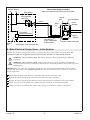
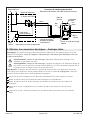
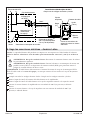
6. Make Electrical Connections – Latin America
NOTE: The electrical rating of the product is printed on a label on the lumbar end of the bath. All
vibracoustic baths are designed to operate between 110 V and 240 V at either 50 Hz or 60 Hz.
WARNING: Risk of electric shock. Disconnect the power before performing the following
procedures.
WARNING: Risk of electric shock. Connect the bath to a properly grounded Ground-Fault
Circuit-Interrupter (GFCI) or Residual Current Device (RCD) for protection against line-to-ground
shock hazard.
IMPORTANT! The white wire should be connected to the load neutral terminal on the GFCI or RCD
breaker. The green wire is the equipment ground and must be connected to the neutral bus in the main
circuit breaker box.
Follow local electrical codes. Bond in accordance with national and local codes.
Remove the 120 V plug from the end of the electrical cord on the amplifier.
Remove the 120 V plug from the electrical cord on the junction box mounted to the control board.
Connect service to the amplifier with a 240 V plug (not included) or hardwire connection.
Connect service to the junction box with a 240 V plug (not included) or hardwire connection.
Junction
Box
Black
(L1)
Wire Connector
Green
(Ground)
From Control
White
(Neutral)
Provide suitable strain relief.
*Connections at the Circuit Breaker
Typical 240 V Wiring Connection
Field Wiring
(From Junction Box
to Breaker Box)
Equipment Ground*
Line Neutral
(White Curly Wire)*
Neutral
Bus
240 V
Typical Single-Pole
Circuit Breaker
with GFCI
Breaker Box
L1N
240 VAC Source
Bond in accordance with national and local codes.
Load Neutral
1212240-2-B 8 Kohler Co.

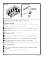
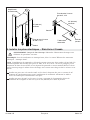
7. Route the Cables
IMPORTANT! Several of the included bath components will be powered by the control amplifier via 25’
(7.6 m) cables. Plan the location of the control amplifier so the cables will reach without tension.
Connect the Cables at the Heated Surface Control
NOTE: The heated surface control is mounted to the board at the end of the bath.
Connect the larger Ethernet end of the user interface cable to one of the two ports on the heated
surface control.
Connect the inter-connect cable (both ends are Ethernet) for the amplifier to the open port on the
heated surface control.
Route the Cables Through the Framing
Carefully cut the cable tie securing the coiled transducer wires to the back of the bath.
Route the transducer wires through the framing to the control amplifier location, drilling 1″ (52 mm)
holes where needed.
If equipped, route the chromatherapy cable from the bath to the planned amplifier location. Follow
the same route as the transducer cables.
Route the inter-connect cable from the heated surface control to the control amplifier location.
Include a drip loop.
Route the user interface cable through the framing from the heated surface control to the planned
user interface location. Include a drip loop.
NOTE: An auxiliary cable connection can be used to pair a BLUETOOTH
®
device or other
battery-operated audio device so users can play their own music with the vibracoustic bath.
If used, route an auxiliary-in cable (not included) to the control amplifier location.
Inter-Connect
Cable
User Interface Cable
Heated
Surface
Control
User Interface
Transducer Wires
Control Board
Inter-Connect
Cable
Heated Surface
Control
Chromatherapy
Cable (If Equipped)
Optional Auxiliary-In
Cable
Drip
Loop
Kohler Co. 9 1212240-2-B

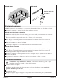
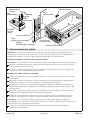
8. Install the Control Amplifier
WARNING: Risk of electric shock. Connect the control amplifier to a properly grounded,
grounding-type receptacle protected by a Ground-Fault Circuit-Interrupter (GFCI) or Residual
Current Device (RCD). Do not remove the grounding pin from the plug or use a grounding adapter.
IMPORTANT! Keep insulating materials away from the control amplifier. Provide an unobstructed air
space around the control amplifier to permit cooling.
NOTE: Do not remove the mounting brackets from the control amplifier.
Position the amplifier flush or recessed from the front of the studs.
Using the wood screws provided, secure the control amplifier to the framing. Use the anchors
provided if securing to a wall material other than wood.
NOTE: To make wiring connections more accessible, temporarily secure the control amplifier with one
screw on each side to allow the amplifier to tilt forward. Once wiring connections are made, secure the
control amplifier with the remaining screws.
Remove the cover from the control amplifier by removing the four screws. Retain for reinstallation.
NOTE: The transducer terminals and wires are numbered to identify the correct connections. When
required, the control amplifier can be removed to aid in the wire connection process.
Securely attach the transducer wires to the transducer terminals. The white with black wires are the
positive (+) leads.
If equipped, connect the chromatherapy connector to the chromatherapy terminal.
Connect the inter-connect cable from the control box to the amplifier.
If used, connect the optional auxiliary-in RCA connectors to the auxiliary-in terminals.
Reinstall the cover to the control amplifier with the four screws.
Plug the control amplifier into the electrical outlet.
Plug the junction box cord into the electrical outlet.
Auxiliary In
Chromatherapy
(If Equipped)
Inter-Connect
Cable
Screws
Alternate Holes
Transducer Wiring
Screws
Cover
Grounded Outlet
Experience
Data Module
Control
Amplifier
1212240-2-B 10 Kohler Co.

9. Complete the Finished Walls
Cover the framing with water-resistant material.
Provide suitable access to the control amplifier.
Install the finished wall and deck materials.
Drill a 5/8″ (16 mm) hole through the wall material where the user interface will be installed. Refer
to the ″Plan the Installation″ section for the recommended location.
Route the user interface cable through the hole in the wall material, and tape or otherwise secure
the cable so it will not fall between the walls.
Seal the joints between the bath rim and the finished deck with silicone sealant.
Install the faucet trim.
Water-Resistant
Deck Material
5/8" (16 mm) User
Interface Hole
Finished Material
Apply silicone
sealant.
Silicone Sealant
24"
(610 mm)
10"
(254 mm)
Kohler Co. 11 1212240-2-B

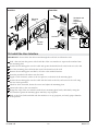
10. Install the User Interface
IMPORTANT! Do not allow the cable routed through the wall hole to fall into the wall.
Push a thin nail into the groove in the back side of the user interface to separate the interface from
the mounting plate.
Position the mounting plate over the cable and against the finished wall so the hooks are to the left.
Level the mounting plate and mark the screw hole locations on the wall.
Remove the mounting plate and drill 1/4″ holes at the marked locations.
Insert the provided wall anchors into the holes.
Apply a bead of silicone sealant to the two grooves on the back of the mounting plate.
Position the mounting plate over the cable with the hooks to the left, and secure to the wall using
the two screws provided.
Check for level. If needed, loosen the screws and adjust the mounting plate.
Connect the cable to the user interface.
Engage the edge of the user interface with the two mounting plate hooks, then firmly swing the
user interface against the mounting plate until they snap together.
Refer to the User Guide included with the interface to set up, program, and verify proper function
of the product.
Anchors
Horizontal and
Vertical
Adjustment
Hooks
Screws
Pencil
Silicone
Sealant
Front ViewBack View
Mounting
Plate
User
Interface
1212240-2-B 12 Kohler Co.

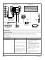
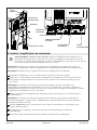
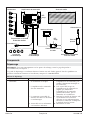
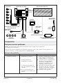
Components
Troubleshooting
NOTE: For service parts information, visit your product page at www.kohler.com/serviceparts.
This troubleshooting guide is for general aid only. For service and installation issues or concerns, call
1-800-4KOHLER.
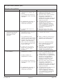
Troubleshooting Table
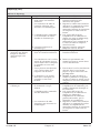
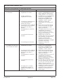
Symptom Probable Cause Recommended Action
1. No sound; no experiences
are functioning.
A. Power to the control amplifier is
off.
A. Reset the circuit breaker to the
control amplifier, then check the
electrical power supply and
connections.
B. Control amplifier must be reset. B. If the red LED on the control
amplifier is not blinking, unplug the
control amplifier for 30 seconds,
then plug in and restart.
C. Experiences data module
connection is loose or damaged.
C. Inspect the data module for loose
connection or damage. Secure the
connection or replace the module as
needed.
D. An experience has not been
selected on the user interface.
D. Select an experience.
E. Vibracoustic intensity is muted
on the user interface.
E. Touch the [Mute] icon on the user
interface to turn off the mute
setting.
Heated SurfaceControl AmplifierTransducers
Chromatherapy
Lights
Chromatherapy
Control
AC Power
AC Power
User Interface
Heated Surface
Control
Heated Surface
Power Supply
Junction
Box
Experience Data
Module Location
Red
LED
Red
LED
Kohler Co. 13 1212240-2-B

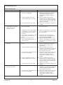
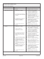
Troubleshooting (cont.)
Troubleshooting Table
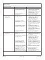
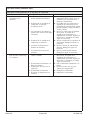
Symptom Probable Cause Recommended Action
F. User interface cable connections
are loose or damaged.
F. Inspect the cables between the user
interface, heated surface control,
and control amplifier. Secure
connections or replace cables as
needed.
G. Control amplifier or heated
surface control does not work.
G. If the red LED on the control
amplifier does not blink following
restart, check the control amplifier
and/or heated surface control and
replace as needed.
H. User interface does not work. H. Check the user interface. Replace as
needed.
2. Music is distorted
(undesirable resonance)
when vibracoustic
functions are on.
A. Intensity setting is too high on
the user interface.
A. Turn down the intensity setting on
the user interface.
B. Transducers on the back surface
of the bath are in direct contact
with framing, joists, or other
materials.
B. Remove or reposition any materials
that are making direct contact with
the transducers.
C. One or more transducers on the
back surface of the bath are
loose.
C. Rotate the loose transducer(s)
clockwise with your fingers until
tight. Do not overtighten.
D. The bath is making direct
contact with framing, joists, or
other materials.
D. Identify the point of contact and
correct it. The bath must not make
contact with any framing or support
materials.
3. User interface does not
light up.
A. Power to the control amplifier is
not on.
A. Reset the circuit breaker to the
control amplifier, then check the
electrical power supply and
connections.
B. Control amplifier must be reset. B. If the red LED on the control
amplifier is not blinking, unplug the
control amplifier for 30 seconds,
then plug in and restart.
C. User interface cable connections
are loose or damaged.
C. Inspect the cables between the user
interface, heated surface control,
and control amplifier. Secure
connections or replace cables as
needed.
D. Control amplifier or heated
surface control does not work.
D. If the red LED on the control
amplifier does not blink following
restart, check the control amplifier
and/or heated surface control and
replace as needed.
E. User interface does not work. E. Check the user interface. Replace as
needed.
4. User interface lights up
but does not work.
A. Control amplifier must be reset. A. If the red LED on the control
amplifier is not blinking, unplug the
control amplifier for 30 seconds,
then plug in and restart.
B. User interface cable connections
are loose or damaged.
B. Inspect the cables between the user
interface, heated surface control,
and control amplifier. Secure
connections or replace cables as
needed.
1212240-2-B 14 Kohler Co.

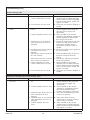
Troubleshooting (cont.)
Troubleshooting Table
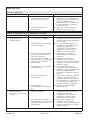
Symptom Probable Cause Recommended Action
C. Control amplifier or heated
surface control does not work.
C. If the red LED on the control
amplifier does not blink following
restart, check the control amplifier
and/or heated surface control and
replace as needed.
D. User interface does not work. D. Check the user interface. Replace as
needed.
5. Auxiliary music does not
work.
A. Power to the control amplifier is
not on.
A. Reset the circuit breaker to the
control amplifier, then check the
electrical power supply and
connections.
B. Control amplifier must be reset. B. If the red LED on the control
amplifier is not blinking, unplug the
control amplifier for 30 seconds,
then plug in and restart.
C. Auxiliary-in or user interface
cable connections are loose or
damaged.
C. Inspect the cables between the user
interface, heated surface control,
and control amplifier. Secure
connections or replace cables as
needed.
D. Auxiliary music source option is
not selected on the user
interface.
D. Select the auxiliary music option on
the user interface.
E. Vibracoustic sound is muted on
the user interface.
E. Touch the [Mute] icon on the user
interface to turn off the mute
setting.
F. Vibracoustic intensity is turned
down on the user interface.
F. Turn up the vibracoustic intensity
on the user interface.
G. Control amplifier or heated
surface control does not work.
G. If the red LED on the control
amplifier does not blink following
restart, check the control amplifier
and/or heated surface control and
replace as needed.
H. User interface does not work. H. Check the user interface. Replace as
needed.
(Optional) Chromatherapy Troubleshooting Table
Symptom Probable Cause Recommended Action
1. Chromatherapy lights do
not work.
A. Power to the control amplifier is
off.
A. Reset the circuit breaker to the
control amplifier, then check the
electrical power supply and
connections.
B. Control amplifier must be reset. B. If the red LED on the control
amplifier is not blinking, unplug
the control amplifier for 30
seconds, then plug in and restart.
C. Chromatherapy feature has not
been selected on the user
interface.
C. Select the Chromatherapy feature
on the user interface.
D. Chromatherapy or user interface
cable connections are loose or
damaged.
D. Inspect the cables for loose
connections or damage. Secure or
replace cables as needed.
E. Control amplifier does not
work.
E. If the red LED on the control
amplifier does not blink following
restart, check the control amplifier
and replace as needed.
Kohler Co. 15 1212240-2-B

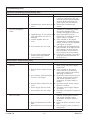
Troubleshooting (cont.)
(Optional) Chromatherapy Troubleshooting Table
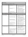
Symptom Probable Cause Recommended Action
F. User interface does not work. F. Verify that the user interface cable
is securely connected to the user
interface and the control amplifier
terminal. If the connections are
good, replace the user interface.
G. Chromatherapy control does not
work.
G. Replace the Chromatherapy
control.
2. Chromatherapy lights do
not cycle through all
colors.
A. Control amplifier must be reset. A. If the red LED on the control
amplifier is not blinking, unplug
the control amplifier for 30
seconds, then plug in and restart.
B. Chromatherapy or user interface
cable connections are loose or
damaged.
B. Inspect the cables for loose
connections or damage. Secure or
replace cables as needed.
C. Control amplifier does not
work.
C. If the red LED on the control
amplifier does not blink following
restart, check the control amplifier
and replace as needed.
D. User interface does not work. D. Cycle through the Chromatherapy
light functions. If the lights do not
cycle through all colors and the
blue icon on the user interface is
not lit, replace the user interface.
E. If none of the recommended
actions correct the problem,
contact Kohler Co.
E. Contact the Customer Care Center
using the contact information on
the back cover.
Heated Surface Troubleshooting Table
Symptoms Probable Cause Recommended Action
1. Heated surface does not
turn on.
A. No power to the power supply. A. Set/reset GFCI or RCD breaker;
check wiring and power supply
connections.
B. Heated surface control must be
reset.
B. If the red LED on the heated
surface control is not blinking,
unplug the control for 30 seconds,
then plug in and restart.
C. User interface cable connections
are loose or damaged.
C. Inspect the cables between the user
interface, heated surface control,
and control amplifier. Secure
connections or replace cables as
needed.
D. Heated surface control does not
work.
D. Check the heated surface control.
Replace as needed.
E. Power supply does not work. E. Check the power supply. Replace
as needed.
F. User interface does not work. F. Check the user interface. Replace as
needed.
2. Bath is on, but there is
little or no heat.
A. Heater cable loose or damaged. A. Inspect the cables between the user
interface, heated surface control,
and control amplifier. Secure
connections or replace cables as
needed.
B. Heater/insulation loose on the
bath.
B. Secure the heater/insulation to the
bath.
C. Heat indicator is set to low heat. C. Press the plus [+] icon to increase
temperature.
1212240-2-B 16 Kohler Co.

Troubleshooting (cont.)
Heated Surface Troubleshooting Table
Symptoms Probable Cause Recommended Action
D. Heater does not work. D. Replace the heater.
E. Temperature sensor does not
work.
E. Replace the heater.
Kohler Co. 17 1212240-2-B
Page is loading ...
Page is loading ...
Page is loading ...
Page is loading ...
Page is loading ...
Page is loading ...
Page is loading ...
Page is loading ...
Page is loading ...
Page is loading ...
Page is loading ...
Page is loading ...
Page is loading ...
Page is loading ...
Page is loading ...
Page is loading ...
Page is loading ...
Page is loading ...
Page is loading ...
Page is loading ...
Page is loading ...
Page is loading ...
Page is loading ...
Page is loading ...
Page is loading ...
Page is loading ...
Page is loading ...
Page is loading ...
Page is loading ...
Page is loading ...
Page is loading ...
Page is loading ...
Page is loading ...
Page is loading ...
Page is loading ...
Page is loading ...
Page is loading ...
Page is loading ...
Page is loading ...
Page is loading ...
Page is loading ...
Page is loading ...
Page is loading ...
-
 1
1
-
 2
2
-
 3
3
-
 4
4
-
 5
5
-
 6
6
-
 7
7
-
 8
8
-
 9
9
-
 10
10
-
 11
11
-
 12
12
-
 13
13
-
 14
14
-
 15
15
-
 16
16
-
 17
17
-
 18
18
-
 19
19
-
 20
20
-
 21
21
-
 22
22
-
 23
23
-
 24
24
-
 25
25
-
 26
26
-
 27
27
-
 28
28
-
 29
29
-
 30
30
-
 31
31
-
 32
32
-
 33
33
-
 34
34
-
 35
35
-
 36
36
-
 37
37
-
 38
38
-
 39
39
-
 40
40
-
 41
41
-
 42
42
-
 43
43
-
 44
44
-
 45
45
-
 46
46
-
 47
47
-
 48
48
-
 49
49
-
 50
50
-
 51
51
-
 52
52
-
 53
53
-
 54
54
-
 55
55
-
 56
56
-
 57
57
-
 58
58
-
 59
59
-
 60
60


Ask a question and I''ll find the answer in the document
Finding information in a document is now easier with AI
in other languages
Related papers
-
Kohler K-1174-GVB-47 Installation guide
-
Kohler K-1124-VBRAW-7 Installation guide
-
Kohler K-1167-GVR-0 Installation guide
-
Kohler K-1357-VB-0 Installation guide
-
-
-
-
-
-
Other documents
-
Bell PTC200GYB Installation guide
-
-
DMF DRDHNJC User manual
-
MTI 75 Installation And Operational Manual
-
DMF DID4 User manual
-
Humminbird Trolling Motor Transducer Installation guide
-
Hubbell Wiring Device-Kellems PD2490 PD1030 Installation guide
-
Spectrum Industries 55473-CAB User manual
-
-
APC INWALLKIT-WHT User manual