Generac 5943-5 Owner's manual
- Category
- Power generators
- Type
- Owner's manual
This manual is also suitable for
Page is loading ...

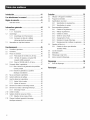
introduction.............................................................1
ReadthisiVlanualThoroughly.................................1
Safety Rules...........................................................1
StandardsIndex.............................................................3
Generalinformation................................................4
1.1 Unpacking......................................................................4
1.1.1 Accessories.......................................................4
1.2 Assembly.......................................................................4
1.2.1 Assemblingthe AccessoryKit............................4
1.2.2 BatteryCableConnection(ElectricStart Only)....4
1.3 EmissionsInformation....................................................5
Operation................................................................5
2.1 Knowthe Generator.......................................................5
2.2 Hourmeter......................................................................6
2.3 ConnectionPlugs...........................................................6
2.3.1 120 VAC,20 Amp, DuplexReceptacle...............6
2.3.2 120 VAC,20 Amp, GFCIDuplexReceptacle
(CARBonly)......................................................7
2.3.3 120/240VAC,30 Amp, Receptacle....................7
2.4 Howto Usethe Generator..............................................7
2.4.1 Groundingthe GeneratorWhenUsedas a
Portable.............................................................8
2.4.2 Connectingthe Generatorto a Building's
ElectricalSystem...............................................8
2.5 Don'tOverloadthe Generator..........................................8
2.6 WattageReferenceGuide...............................................9
2.7 BeforeStartingtheGenerator.........................................9
2.7.1 Adding EngineOil..............................................9
2.7.2 Adding Gasoline...............................................10
2.8 Starting Pull Start Engines............................................10
2.9 Starting ElectricStart Engines......................................11
2.9.1 ManualStart....................................................11
2.10 Stoppingthe Engine.....................................................11
2.11 LowOil LevelShutdownSystem..................................11
2.11.1 SensingLowOil Level......................................11
2.12 Chargingthe Battery(ElectricStart UnitsOnly).............12
Maintenance.........................................................12
3.1 PerformingScheduledMaintenance.............................12
3.2 MaintenanceSchedule.................................................12
3.3 ProductSpecifications..................................................12
3.3.1 GeneratorSpecifications..................................12
3.3.2 EngineSpecifications.......................................12
3.4 GeneralRecommendations...........................................13
3.4.1 GeneratorMaintenance....................................13
3.4.2 ToCleanthe Generator.....................................13
3.4.3 EngineMaintenance.........................................13
3.4.4 CheckingOil Level...........................................13
3.4.5 Changingthe Oil..............................................13
3.4.6 Replacingthe SparkPlug.................................13
3.4.7 BatteryReplacement(IfApplicable).................14
3.5 ServiceAir Filter...........................................................14
3.5.1 CleanSparkArrestor Screen(CARBModels)...14
3.6 ValveClearance............................................................15
3.7 General........................................................................15
3.8 Long TermStorage.......................................................15
3.9 OtherStorageTips.......................................................15
Troubleshooting....................................................16
4.1 TroubleshootingGuide..................................................16
Notes....................................................................17
MANUALDELPROPIETARIO.....................19
MANUELD'ENTRETIEN......................................39

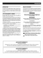
INTRODUCTION
Thankyou for purchasingthis modelby GeneracPowerSystems,
Inc. This model is a compact, high performance, air-cooled,
engine driven generatordesigned to supply electrical power to
operateelectrical loads where no utility power is availableor in
placeof utility dueto a poweroutage.
BEADTHiSMANUALTHOROUGHLY
If anyportion ofthis manualis notunderstood,contactthenearest
AuthorizedDealerfor starting, operatingandservicingprocedures.
The operator is responsible for proper and safe use of the
equipment.We strongly recommendthat the operator read this
manualandthoroughlyunderstandall instructionsbeforeusingthe
equipment.Wealsostronglyrecommendinstructingotherusersto
properlystart andoperatethe unit.This preparesthem ifthey need
to operatetheequipmentin an emergency.Savethese instructions
for future reference.If you loan this deviceto someone,ALWAYS
loanthese instructionsto the individualaswell.
Thegeneratorcan operatesafely,efficiently and reliablyonly if it
is properlylocated,operatedand maintained.Beforeoperatingor
servicingthe generator:
• Becomefamiliarwith and strictly adhereto all local, stateand
nationalcodes and regulations.
• Study all safety warnings in this manual and on the product
carefully.
• Becomefamiliarwith thismanualandthe unitbeforeuse.
Themanufacturercannot anticipateevery possible circumstance
that might involvea hazard.Thewarnings in this manual,and on
tags and decals affixedto the unit are,therefore,not all inclusive.
If usinga procedure,work method or operatingtechniquethat the
manufacturerdoes not specifically recommend,ensurethat it is
safe for others. Also make sure the procedure,work method or
operatingtechnique utilizeddoes not renderthe generatorunsafe.
THE INFORMATIONCONTAINEDHEREIN WAS BASED ON
MACHINESIN PRODUCTIONAT THE TIME OF PUBLICATION.
GENERACRESERVESTHERIGHTTOMODIFYTHISMANUALAT
ANYTIME.
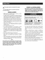
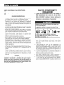
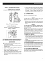
SAFETYRULES
Throughoutthis publication,and on tags and decals affixedto the
generator,DANGER,WARNING,CAUTIONand NOTEblocks are
usedto alert personnelto special instructionsabout a particular
operation that may be hazardous if performed incorrectly or
carelessly.Observethem carefully.Theirdefinitionsareasfollows:
INDICATESAHAZARDOUSSiTUATiONORACTIONWHICH,IF
NOTAVOIDED,WILLRESULTIN DEATHORSERIOUSINJURY.
Indicatesa hazardoussituationor action which,if not
avoided, couldresultindeathorseriousinjury.
_CAUTION!
Indicatesa hazardoussituationor action which,if not
avoided, couldresultinminoror moderateinjury.
NOTE:
Notescontainadditionalinformationimportantto a procedure
and willbe foundwithinthe regular textbodyofthis manual.
These safety warnings cannot eliminate the hazards that they
indicate. Common sense and strict compliancewith the special
instructionswhile performingtheaction or serviceareessentialto
preventingaccidents.
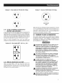
Four commonly used safety symbols accompany the DANGER,
WARNINGand CAUTIONblocks. The type of information each
indicatesis asfollows:
,_This symbol points out important safety
information that, if not followed, could
endanger personal safety and/or property of
others.
This symbol points out potential explosion
hazard.
WARNING!
California Proposition 65
Engine exhaust and some of its constituents are known to the state of California to cause cancer,
birth defects, and other reproductive harm.
WARNING!
California Proposition 65
This product contains or emits chemicals known to the state of California to cause cancer,
birth defects, and other repoductive harm.

i/_This symbol points out potential fire hazard.
This symbol points out potential electrical
shock hazard.
GENERAL HAZARDS
* NEVERoperatein an enclosed area, in a vehicle, or indoors
EVENIFdoorsand windows areopen.
* For safety reasons, the manufacturer recommends that the
maintenanceof this equipmentis carried out by an Authorized
Dealer.Inspectthe generatorregularly,and contactthe nearest
AuthorizedDealerfor parts needingrepair or replacement.
* Operategeneratoronly on levelsurfacesandwhereit will notbe
exposedto excessivemoisture,dirt, dust or corrosivevapors.
* Keep hands, feet, clothing, etc., away from drive belts, fans,
and othermoving parts. Neverremoveanyfan guardor shield
whilethe unitis operating.
* Certain parts of the generator get extremely hot during
operation. Keep clear of the generatoruntil it has cooled to
avoidsevereburns.
* Do NOToperategeneratorin the rain.
* Do not alter the construction of the generator or change
controlswhich might createan unsafeoperatingcondition.
* Never start or stop the unit with electrical loads connected
to receptaclesAND with connecteddevicesturned ON. Start
the engine and let it stabilize before connecting electrical
loads. Disconnectall electricalloadsbeforeshuttingdown the
generator.
* Do notinsert objectsthrough unit's coolingslots.
* When working on this equipment, remain alert at all times.
Never work on the equipment when physically or mentally
fatigued.
* Neverusethe generatoror anyof its parts as a step. Stepping
on the unit can stress and break parts, and may result in
dangerousoperating conditions from leakingexhaust gases,
fuel leakage,oil leakage,etc.
NOTE:
This generatormaybe equippedwith a spark arrestormuffler.
The spark arrestor must be maintainedin effective working
orderbytheowner/operator.In theStateofCalifornia, a spark
arrestor is required by law (Section 4442 of the California
Public Resources Code). Other states may havesimilar laws.
Federallawsapply on federallands.
EXHAUST & LOCATIONHAZARDS
• Neveroperatein anenclosedareaor indoors!NEVERuse in
thehome,in a vehicle, or in partlyenclosedareas suchas
garages,EVENiF doors and windowsare open! ONLYuse
outdoors and far from open windows,doors, vents,andinan
areathatwill notaccumulate deadly exhaust.
Using a generator indoors CAN KiLL YOU iN MINUTES.
Generator exhaust contains carbon monoxide. This is
a poison you cannot see or smeJJ.
NEVER use insidea home
or garage, EVEN iF doors
and windows areopen.
Only use OUTSIDE and
far away from windows,
doors, and vents.
* The engine exhaustfumes contain carbon monoxide, which
you cannot see or smell. This poisonous gas, if breathedin
sufficientconcentrations,cancause unconsciousnessor even
death.
* Adequate, unobstructed flow of cooling and ventilating air
is critical to correct generator operation. Do not alter the
installation or permit even partial blockage of ventilation
provisions, as this can seriously affect safe operationof the
generator.ThegeneratorMUSTbeoperatedoutdoors.
* This exhaustsystem must be properlymaintained.Do nothing
thatmightrendertheexhaustsystemunsafeorinnoncompliance
with any localcodes and/orstandards.
* Alwaysusea batteryoperatedcarbonmonoxidealarmindoors,
installedaccordingto themanufacturer'sinstructions.
* If you start to feel sick, dizzy,or weak after the generatorhas
beenrunning,move tofresh air IMMEDIATELYSeea doctor,as
you couldhavecarbonmonoxidepoisoning.

ELECTRICALHAZARDS
• The generator produces dangerously high voltage when in
operation.Avoidcontactwith barewires,terminals,connections,
etc., whilethe unitis running,evenon equipmentconnectedto
thegenerator.Ensureall appropriatecovers,guardsandbarriers
are in placebeforeoperatingthe generator.
• Never handle any kind of electrical cord or device while
standingin water,whilebarefootor while handsor feet arewet.
DANGEROUSELECTRICALSHOCKMAYRESULT.
• TheNationalElectricCode(NEC)requirestheframeandexternal
electrically conductive parts of the generator be properly
connectedto an approvedearth ground.Localelectricalcodes
may also require proper grounding of the generator.Consult
with a localelectricianfor groundingrequirementsin thearea.
• Use a ground fault circuit interrupterin any damp or highly
conductivearea(such as metaldecking or steelwork).
• Do not useworn, bare,frayedor otherwisedamagedelectrical
cord setswith the generator.
• Beforeperforminganymaintenanceonthegenerator,disconnect
the engine starting battery (if equipped)to preventaccidental
start up. Disconnectthe cablefrom the battery post indicated
by a NEGATIVE,NEGor (-) first. Reconnectthatcable last.
• In caseof accidentcausedby electricshock,immediatelyshut
down the source of electrical power. If this is not possible,
attempt to free the victim from the live conductor. AVOID
DIRECTCONTACTWITH THE VICTIM. Use a non-conducting
implement,such asa ropeor board,to freethevictim from the
live conductor.If the victim is unconscious,applyfirst aid and
getimmediatemedical help.
FIREHAZARDS
• GasolineishighlyFLAMMABLEanditsvaporsare EXPLOSIVE.
Never permit smoking,open flames, sparksor heat in the
vicinitywhile handlinggasoline.
• Neveraddfuel while unitis runningor hot.Allow engineto cool
completelybeforeaddingfuel.
• Never fill fuel tank indoors, Comply with all laws regulating
storageand handlingof gasoline.
• Do not overfill the fuel tank. Always allow room for fuel
expansion.If tank is over-filled,fuel can overflow onto a hot
engineandcause FIREor an EXPLOSION.Neverstoregenerator
with fuel in tank where gasolinevapors might reachan open
flame, spark or pilot light (as on a furnace, water heateror
clothes dryer). FIREor EXPLOSIONmay result. Allow unit to
cool entirelybeforestorage.
• Wipe up any fuel or oil spills immediately. Ensure that no
combustiblematerialsareleft onor nearthe generator.Keepthe
areasurroundingthe generatorcleanand freefrom debrisand
keepa clearanceof five (5) feet on all sideto allow for proper
ventilationofthe generator.
• Do notinsert objectsthrough unit's cooling slots.
• Never operate the generator if connected electrical devices
overheat,if electricaloutputislost, if engineor generatorsparks
or ifflames or smokeare observedwhileunit is running.
• Keepafire extinguishernearthe generatoratalltimes.
STANDARDS/NDEX
1. NationalFireProtectionAssociation(NFPA)70:TheNATIONAL
ELECTRICCODE(NEC)availablefrom www.nfpa.org
2. NationalFire ProtectionAssociation (NFPA)5000: BUILDING
CONSTRUCTIONAND SAFETYCODEavailablefrom www.
nfpa.org
3. InternationalBuildingCodeavailablefrom www.iccsafe.org
4. Agricultural Wiring Handbookavailablefrom www.rerc.org ,
Rural ElectricityResourceCouncil RO.Box 309 Wilmington,
OH45177=0309
5. ASAEEP-364.2Installationand Maintenanceof FarmStandby
Electric Power available from www.asabe.org, American
Society of Agricultural & Biological Engineers2950 Niles
Road,St. Joseph,MI 49085
This list is not all inclusive.Checkwith theAuthority HavingLocal
Jurisdiction (AHJ)for any localcodes or standardswhich may be
applicableto yourjurisdiction.
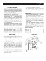
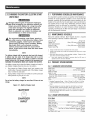
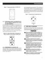
MODELNO:
SERIALNO:
Unit ID Location
DATA
DECAL

1.1 UNPACKING
• Removeallpackagingmaterial.
• Removeseparateaccessorybox.
• Removethe generatorfrom carton.
1.1.1 ACCESSORIES
Checkall contents.If anyparts aremissing or damaged,locatean
authorizeddealerat 1-888-436-3722.
• 1 - Owner'sManual • 1 - HandleAssembly
• 1-LiterOiISAE30 • 2-FrameFoot
• 2 - Never-FlatWheels • 1 - 20' PowerCord
• 3 - ProductRegistrationCards (006110-3 only)
• 1 - ServiceWarranty • 1 - EmissionsWarranty
e
e
1 - Battery Charger (Electric Start Models)
1 - Hardware Bag (containing the following):
- 2-RubberFeet 6-M8 Bolt (Long)
- 2-1/2" AxlePins 2-M6 Bolts (Long)
- 2-Cotter Pins 2-M8 Acorn Nut
- 2-1/2" FlatWashers 4-HexFlangedM8Nuts
- 2-HexFlangedM6 Nuts
1.2 ASSEMBLY
The generator requires some assembly prior to using it. If
problems arise when assemblingthe generator,please call the
GeneratorHetplineat 1-888-436-3722.
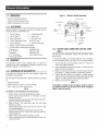
1.2.1 ASSEMBLINGTHEACCESSORYKIT
The wheels are designed into the unit to greatly improve the
portability ofthe generator.
You will needthe following tools to properlyinstall the accessory
kit.
• NeedleNosePliers
• Ratchetand8mm, lOmm, and13mm sockets
• 8mm, lOmm, and13mm boxwrenches
NOTE:
The wheels are not intendedfor over-the-road use.
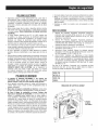
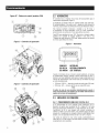
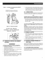
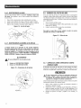
1. Refer to Figure 1 and install the Wheels as follows:
- Slidethe AxlePinthroughtheWheel, 1/2" FlatWasher,andWheel
Bracketon theframe.
- Insertthe CotterPinthroughthe AxlePinthenbendthetabs (ofthe
OotterPins)outwardto lock into place.
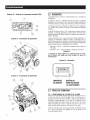
2. Refer to Figure 1 and install the Frame Foot and Rubber
Bumpers as shown.
- Slidethe RubberBumperstuds throughthe FrameFoottheninstall
the LockingFlangeNuts.
- Slidethe HexHeadBoltsthrough theholes inthe FrameRail.
- Slide the Frame Foot onto the Hex Head Bolts then install the
LockingFlangeNuts.
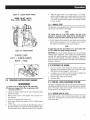
3. Refer to Figure 1 and install the Handle as shown.
- Slidethe long Bolts through the HandleBracketand Handle,then
installthe HexNuts.
Figure 1 - Wheel & Handle Assembly
2 XM8BOLT(LONG)
2 XM8ACORNNUT
ASSEMBLY
4 X M8 BOLT
,(LONG)
2 X COTTER PIN
2 X I/2" FLATWASHER
2 X WHEEL
2 X AXLE PIN
_-'_ ....... 2 X FRAME FOOT
_Z'_ 4XM8NUTS
2 XRUBBER FOOT---_ _ 2 XM6 NUTS
2 XM6BOLT
(LONG)
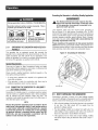
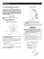
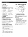
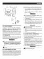
1.2.2 BATTERYCABLECONNECTION(ELECTR/CSTART
ONLY_
The unit has been deliberatelyshipped with the battery cables
disconnected.
Toconnectthe battery,you will needtwo 8mm boxwrenchesto
connectthe batterycables.(seeFigure16 for connectiondetails):
1. Cut off cable ties securing battery cables and remove red
coversfrom batteryterminals.
2. First,connecttheredcableto thepositive(+) batteryterminal
with the bolt andnut supplied.
3. Makesureconnectionsare secureandsliderubber boot over
thepositive (+) batteryterminal and connectionhardware.
4. Connectthe black cable to the negative(-) batteryterminal
with thebolt and nut suppliedand slide rubber boot overthe
negative(-) batteryterminal and connectionhardware.
5. Makesure all connectionsaresecure.
NOTE:
If the battery is unable to start the engine,chargeit with the
12V chargerincludedinthe accessory box(seethe "Charginga
Battery"section for details).

1.3 EMiSSiONSiNFORMATiON
TheEnvironmentalProtectionAgency (andCaliforniaAir Resource
Board for generators certified to CA standards) requires that
this generator comply with exhaust and evaporative emission
standards.Locatethe emissions compliancedecal on the engine
to determinewhatstandardsthegeneratormeets,andto determine
which warranty applies.This generatoris certifiedto operateon
gasoline. The emission control system includes the following
components(if equipped):
• AirInductionSystem
- IntakePipe/ Manifold
- AirCleaner
• FuelSystem
- Carburetor
- FuelTank/Cap
- FuelLines
- EvaporativeVentLines
- CarbonCanister
• IgnitionSystem
- SparkPlug
- IgnitionModule
• ExhaustSystem
- ExhaustManifold
- Muffler
- PulsedAirValve
- Catalyst
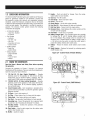
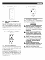
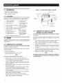
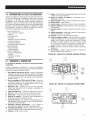
2.1 KNOWTHEGENERATOR
Read the Owner'sManual and Safety Rules before operating
thisgenerator.
Compare the generator to Figures 2 through 4 to become
familiarizedwith thelocationsof variouscontrolsandadjustments.
Savethis manualfor future reference.
1. 120 Volt AC, 20 Amp, Duplex Receptacle - Supplies
electrical power for the operationof 120 Volt AC, 20 Amp,
single-phase, 60 Hz electrical lighting, appliance, tool and
motor loads (CARBmodelsare equippedwith GFCIoutlets).
2. 120/240 Volt AC, 30 Amp LockingReceptacle - Supplies
electricalpowerfor the operationof 120 and/or240 VoltAC,
30 Amp, single-phase,60 Hz, electrical lighting, appliance,
tool andmotor loads.
3. CircuitBreakers (AC)- Eachreceptacleis providedwith a
push-to-resetcircuit breakerto protectthe generatoragainst
electricaloverload.
4. Oil Drain- Useto drainengineoil.
5. Air Filter- Filtersintakeairas itisdrawn intothe engine.
6. ChokeKnob- Usedwhen startinga coldengine.
7. FuelTank- SeegeneratorSpecificationsfor tank capacity.
8. GroundingLug- Groundthe generatorto an approvedearth
groundhere.See"GroundingtheGenerator"for details.
9. Run/Stop Switch- Controls the operationof the generator
(pull start models).
9A. Start Switch - Used to start engine from the starter motor
(electricstart modelsonly).
10. Muffler- Quietsthe engine.
11. Handle - Pivot and retract for storage. Press the spring-
loadedbuttonto move handles.
12. GasCap- Fuelfill location.
l& FuelGauge- Showsfuel levelin tank.
14. Oil Fill- Add oil here.
15. Recoil Starter - Useto start enginemanually.
15. FuelShut Off - Valvebetweenfueltank and carburetor.
17. Roll OverValve- Passesfuelto the engineairbox.
18. Recovery Hose- Installbetweenthe carboncanisterandthe
roll overvalve (if equipped).
19. Hourmeter- Trackshoursof operation.
20. Battery ChargerInput - This receptacleallowsthe capability
to rechargethe 12 volt DO storage battery provided with
the 12 Volt Adaptor Plug Chargerwhich is included in the
Accessory Box. Located behindthe battery chargerinput is
a 1.50 Amp in-line fuse which is insidethe control panelto
protectthe battery(electricstart models only).
21. Battery - Powersthe electric starter (electric start models
only).
22. Spark Arrestor - Reducesfire hazardsby containing sparks
(CARBmodels only).
Figure 2.4 - Contro/ Panel (49 State Models)
Figure 2B - Contro/ Panel (CARB Models)

Figure 2C - Contro/ Pane/ (CSA Models)
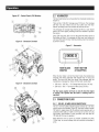
Figure3 - GeneratorControls
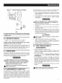
2.2 HOURMETER
TheHourmetertrackshoursofoperationforscheduledmaintenance
(Figure5):
Therewill bea"CHGOIL"messageevery100hours.Themessage
will flash one hour before and one hour after each 100 hour
interval,providinga two hourwindow to perform service.
This messagewill actuallybeginflashing at 99 hoursand disable
itselfat 101 hoursagain,providingatwo hourwindow to perform
theservice.
Every200 hoursthe "SVC"icon on the lower left hand corner of
thedisplay will flash. Themessagewill flash one hourbeforeand
onehour aftereach200 hourintervalprovidingatwo hourwindow
to perform service.
Figure5 - Hourmeter
HOUR GLASS
GRAPHIC
O000.O
RESETBUTTON
(IF EQUIPPED)
Figure4 - Generator Controls
Whenthe hour meter is inthe FlashAlert mode, the maintenance
message will always alternate with elapsedtime in hours and
tenths. The hours wilt flash four times, then alternatewith the
maintenancemessagefourtimes untilthemeter resetsitself.
* 100 hours- CHGOIL-- OilChangeInterval(Every100 hrs)
* 200 hours- SVC-- ServiceAir Filter(Every200 hrs)
Note:
The hour glass graphic will flash on and off when the engine
is running.This signifies that the meter is tracking hours of
operation.
2.3 CONNECTIONPLUGS
2.3.1 120VAC,20AMP,DUPLEXRECEPTACLE
This is a 120 Volt outlet protectedagainst overloadby a 20 Amp
push-to-resetcircuitbreaker(Figure6). Useeachsocketto power
120 VoltAC, singlephase,60 Hzelectricalloadsrequiringupto a
combined 2400 watts (2.4 kW) or 20 Amps of current.Use only
high quality,well-insulated, 3-wire grounded cord sets ratedfor
125 Volts at 20 Amps (or greater).
Keep extensioncords as short as possible, preferablyless than
15 feet long, to preventvoltage drop and possibleoverheatingof
wires.

Figure 6 - 120 Vo/t AC, 20 Amp, Duplex Receptac/e
2.3.2 120VAC,20AMP,GFC/DUPLEXRECEPTACLE
(CARBONLY)
This is a 120 Volt outlet protectedagainst overloadby a 20 Amp
push-to-reset circuit breaker (Figure 6A). Use each socket to
power 120 VoltAO,single phase,60 Hz electricalloadsrequiring
upto a combined2400 watts (2.4 kW)or 20 Amps of current.Use
only high quality,well-insulated,3-wire groundedcord sets rated
for 125 Volts at 20 Amps (or greater).
Keepextensioncords asshort as possibleto preventvoltagedrop
and possibleoverheatingof wires.
Figure 6A - 120 Vo/t AC, 20 Amp, GFC/Duplex
Receptac/e
2.3.3 120/240VAC,30AMPRECEPTACLE
Use a NEMA L14-30 plug with this receptacle (rotate to lock!
unlock). 0onnect a suitable4-wire groundedcord set to the plug
andto thedesiredtoad.Thecordset shouldbe ratedfor 250 Volts
ACat30 Amps (or greater)(Figure7).
Use this receptacleto operate120 Volt AC, 60 Hz, singlephase
loads requiringup to 3600 watts (3.6 kW) of powerat 30 Amps
or 240 Volt AC, 60 Hz,single phase loadsrequiring up to 7200
watts (7.2 kW) of power at 30 Amps. The outlet is protectedby
two 25 Amp (5.5kW)ortwo 30 Amp (6.5kW)push-to-resetor one
30 Amp 2-pole toggleswitch or two 30 Amppush buttonto reset
(6.5/7.5kW) circuit breaker.
Figure 7 - 120/240 VAC, 30 Amp Receptac/e
120V/240V
30A
2.4 HOW TO USETHEGENERATOR
Seethe "To Startthe Engine"sectionfor how to safelystart and
stop the generatorand how to connect and disconnect loads. If
there are any problems operatingthe generator,pleasecall the
generatorhelplineat 1-888-436-3722.
_t ever operate in an enclosed area or indoors!
NEVER use in the home, in a vehicle, or in
partly enclosed areas such as garages, EVEN
IF doors and windows are open! ONLY use
outdoors and far from open windows, doors,
vents, and in an area that will not accumulate
deadly exhaust.
_t The engine exhaust fumes contain carbon
monoxide, which you cannot see or smell.
This poisonous gas, if breathed in sufficient
concentrations, can cause unconsciousness or
even death.
,_Adequate, unobstructed flow of cooling and
ventilating air is critical to correct generator
operation. Do not alter the installation or permit
even partial blockage of ventilation provisions,
as this can seriously affect safe operation
of the generator. The generator MUST be
operated outdoors.
_t This exhaust system must be properly
maintained. Do nothing that might render the
exhaust system unsafe or in noncompliance
with any local codes and/or standards.
_t Always use a battery operated carbon
monoxide alarm indoors, installed according to
the manufacturer's instructions.

Using a generator indoors CAN KiLL YOU iN MINUTES.
GroundingtheGeneratorinaBuildingStandbyApplicati0n
Generator exhaust contains carbon monoxide. This is
a poison you cannot see or smell.
NEVER use inside a home
or garage, EVENiF doors
and windows are open.
Only use OUTSIDE and
far away from windows,
doors, and vents.
2.4.1 GROUNO/NGTHEGENERATORWHENUSEDASA
PORTABLE
This generator has an equipment ground that connects the
generatorframe componentsto the ground terminals on the AC
output receptacles (see NEC 250.34 (A) for explanation).This
allows the generatorto be used as a portablewithout grounding
the frame ofthe generatorasspecifiedin NEC250.34.
SpecialRequirements
There may be Federalor State OccupationalSafety and Health
Administration(OSHA)regulations,localcodes,or ordinancesthat
applyto the intendeduse ofthe generator.
Pleaseconsult a qualified electrician,electrical inspector, or the
local agencyhavingjurisdiction:
* In some areas, generators are requiredto be registeredwith
local utilitycompanies.
* If the generatoris used at a construction site, there may be
additionalregulationswhich must be observed.
2.4.2 CONNECT/NGTHEGENERATORTOABU/LD/NG'$
ELECTRICALSYSTEM
Connectionsfor standby power to a building's electricalsystem
must be made by a qualifiedelectricianand in strict compliance
with all national and local electrical codes and laws. The
connectionmust isolatethegeneratorpowerfrom utility poweror
otheralternativepowersources.
NOTE:
Becausethe generator equipmentground is bondedto the AC
neutralwiresin thegenerator,eithera 3-poletransferswitchor
a 2 poletransferswitchwith a switchingneutralkit is required
to connectthisgenerator to a buildingload.In this application
the generator becomesa separatelyderived system(see NEC
250.20 (D)), and must be grounded in accordance with the
nationalor localelectricalcoderequirements.
,_The National Electrical Code requires that the
frame and external electrically conductive parts
of this generator be properly connected to an
approved earth ground,
Local electrical codes may also require proper grounding of
the unit (Figure8). Forthat purpose, connectinga No. 10 AWG
(AmericanWireGauge)strandedcopperwireto the groundinglug
and to an earth-drivencopperor brass grounding rod (electrode)
provides adequateprotection against electrical shock. However,
local codes may vary widely.Consultwith a localelectricianfor
grounding requirementsin thearea.
Proper groundingof the generatorwill help preventelectrical
shockin theeventof a groundfault conditioninthe generatoror in
connectedelectricaldevices.Propergroundingalsohelpsdissipate
static electricity,which often buildsup in ungroundeddevices.
Figure8 - GroundingtheGenerater
GROUNDING
2.5 DON'TOVERLOADTHEGENERATOR
Overloadinga generatorin excess of its ratedwattage capacity
can result in damageto the generatorandto connectedelectrical
devices.Observethefollowing to preventoverloadingthe unit:
* Addupthetotal wattageofall electricaldevicesto be connected
at one time. This total should NOT be greater than the
generator'swattagecapacity.
* The ratedwattageof lights can betaken from light bulbs. The
ratedwattageof tools, appliancesand motors can usually be
foundon a datalabelor decalaffixedto the device.
* If the appliance,tool or motor does not give wattage,multiply
voltstimes ampereratingto determinewatts (voltsx amps =
watts).

* Some electric motors, such as induction types, require about
threetimes morewatts of powerfor startingthan for running.
This surge of power lasts only a few seconds when starting
such motors.Makesureto allowfor high startingwattagewhen
selectingelectricaldevicesto connectto the generator:
1. Figurethe watts neededto start the largestmotor.
2. Add to that figure the running watts of alt other connected
loads.
TheWattageReferenceGuideis providedto assist in determining
how many itemsthe generatorcan operateatonetime.
NOTE:
All figures are approximate. See data label en appliancefor
wattage requirements.
2.6 WATTAGEREFERENCEGUIDE
Device ................................... RunningWatts
*Air Conditioner(12,000 Btu).......................... 1700
*Air Conditioner(24,000 Btu).......................... 3800
*Air Conditioner(40,000 Btu).......................... 6000
BatteryCharger(20 Amp).............................. 500
BeltSander(3") .................................... 1000
ChainSaw ........................................ 1200
CircularSaw(6-1/2") ........................... 800 to 1000
*Clothes Dryer(Electric) ............................. 5750
*Clothes Dryer(Gas) ................................. 700
*Clothes Washer ................................... 1150
CoffeeMaker ...................................... 1750
*Compressor (1 HP)................................. 2000
*Compressor (3/4 HP)............................... 1800
*Compressor (1/2 HP)............................... 1400
CurlingIron......................................... 700
*Dehumidifier....................................... 650
Disc Sander(9").................................... 1200
EdgeTrimmer....................................... 500
Electric Blanket...................................... 400
Electric NailGun.................................... 1200
Electric Range(per element)........................... 1500
Electric Skillet...................................... 1250
*Freezer............................................ 700
*FurnaceFan(3/5 HP) ................................ 875
*GarageDoor Opener............................ 500to 750
HairDryer......................................... 1200
Hand Drill.................................... 250 to 1100
HedgeTrimmer...................................... 450
Impact Wrench...................................... 500
Iron.............................................. 1200
*Jet Pump ......................................... 800
Lawn Mower....................................... 1200
Light Bulb.......................................... 1O0
Microwave Oven............................... 700 to 1000
*Milk Cooler....................................... 1100
OilBurneron Furnace................................. 300
OilFiredSpaceHeater(140,000 Btu) ..................... 400
OilFiredSpaceHeater(85,000 Btu) ...................... 225
OilFiredSpaceHeater(30,000 Btu) ...................... 150
*Paint Sprayer,Airless (1/3 HP) ......................... 600
PaintSprayer,Airless (handheld)......................... 150
Radio ......................................... 50 to 200
*Refrigerator........................................ 700
SlowCooker........................................ 200
*Submersible Pump(1-1/2 HP) ........................ 2800
*SubmersiblePump (1 HP) ........................... 2000
*SubmersiblePump (1/2 HP).......................... 1500
*Sump Pump................................. 800 to 1050
*Table Saw(10") ............................. 1750to 2000
Television..................................... 200to 500
Toaster..................................... 1000to 1650
WeedTrimmer ...................................... 500
* Allow 3 times the listedwatts for starting these devices.
2.7 BEFORESTARTINGTHEGENERATOR
Priorto operatingthe generator,engineoil and gasolinewill need
to be added,asfollows:
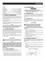
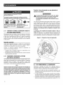
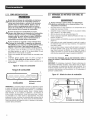
2.7.1 ADDING ENGINEO/L
All oil should meet minimum American PetroleumInstitute (API)
Service Class SJ, SL or better.Use no special additives. Select
the oil's viscosity grade according to the expected operating
temperature(also seechart).
* Above40° F,useSAE30
* Below40° Fand downto 10° F,use10W-30
* All temperatures,usesynthetic5W-30
411lIE
!
°F =20 =10 0 10 20 32
!
40
mml,
60 80 100
Temperature Range of Expected Use
ACAUTION!
,_ Any attempt to crank or start the engine
before it has been properly serviced with the
recommended oil may result in an engine
failure.
1. Placegeneratoron a levelsurface (notto exceed15° inany
direction).
2. Cleanareaaroundoil fill andremoveoil fill cap anddipstick.
3. Wipedipstick clean.
4. Slowly fill engine with oil through the oil flit opening until it
reachesthe fult mark. Stopfilling occasionally to check oil
level.Be carefulnette ever fill.
5. Installoil fill capandfingertighten securely.
6. Checkengineoil levelbeforestarting eachtime thereafter.

2.7.2 ADD/NGGA$O/./NE
Never fill fuel tank indoors. Never fill fuel tank
when engine is running or hot. Avoid spilling
gasoline on a hot engine. Allow engine to cool
entirely before filling fuel tank. DO NOT light a
cigarette or smoke when filling the fuel tank.
Do not overfill the fuel tank. Always leave room
for fuel expansion, if the fuel tank is overfilled,
fuel can overflow onto a hot engine and cause
FiRE or EXPLOSION. Wipe up any spilled fuel
immediately.
Never light a cigarette or smoke when filling
the fuel tank. Gasoline is highly FLAMMABLE
and its vapors are EXPLOSIVE. Never permit
smoking, open flames, sparks or heat in the
vicinity while handling gasoline.
1. UseregularUNLEADEDgasolinewith thegeneratorengine.Do
not use anygasolinewith morethan 10% addedethanol. Do
not useE85 gasoline.Donot mix oil with gasoline.
2. Cleanareaaroundfuelfill cap, removecap.
3. Slowly add unleadedregulargasolineto fuel tank. Becareful
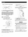
nott0 overfill(Figure9).
4. Installfuel cap andwipe up any spilledgasoline.
Figure9 - FuelTank
FueiTank
_ /
T
Fuel/ Do NOTFillAboveLip
IMPORTANT:It isimportantto preventgumdepositsfrom forming
in fuel system parts such as the carburetor,fuel hose or tank
during storage. Alcohol-blendedfuels (called gasohol, ethanol
or methanol)can attract moisture, which leadsto separationand
formation of acids duringstorage.Acidic gascandamagethefuel
system of an enginewhile in storage.Toavoid engineproblems,
the fuel system should be emptiedbefore storageof 30 daysor
longer.Seethe "Storage"section. Neveruseengineor carburetor
cleanerproductsin thefueltank aspermanentdamagemay occur.
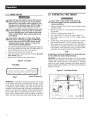
2.8 STARTINGPULLSTARTENGINES
Never start or stop engine with electrical
devices plugged into the receptacles AND
devices turned on.
1. Unplugall electricalloads from the unit's receptaclesbefore
startingthe engine.
2. Makesurethe unit is in a levelposition (notto exceed15° in
anydirection).
3. OPENthe FuelShut-offValve(Figure10).
4. TurnengineRUN/STOPswitch to ONposition(Figure11).
5. Slide engine choke to the LEFT to FULL CHOKEposition
(Figure12).
6. Tostart engine,firmly graspthe recoilhandleandpull slowly
until increasedresistanceisfelt. Pullrapidlyup and away.
7. Whenenginestarts, movechokeknobto 1/2-CHOKEposition
until engine runs smoothly and then fully into RUNposition.
If enginefalters,move chokeback outto 1/2-CHOKEposition
until engineruns smoothly andthento RUNposition.
NOTE:
If engine fires, but does not continueto run,movechokelever
to FULLCHOKEand repeatstartinginstructions.
iMPORTANT:Donotoverloadthe generator.Also, do not overload
individual panel receptacles.These outlets are protectedagainst
overload with push-to-reset-type circuit breakers. If amperage
rating of any circuit breakeris exceeded,that breakeropensand
electricaloutputtothat receptacleis lost.Read"Don't Overloadthe
Generator"carefully.
Figure 10- FuelShut-o#Valve
1o

Figure 11 - Engine ON/OFF Switch
ENGINE ON/OFF SWITCH
(PULL START ENGINES ONLY)
Figure 12 - Choke Position
CHOKELEVER
LEFT= CHOKE(START)
RIGHT= RUN
2.9 STARTINGELECTRICSTARTENGINES
Never start or stop engine with electrical
devices plugged into the receptacles AND
devices turned on.
1. Unplugall electrical loadsfrom the unit's receptaclesbefore
startingthe engine.
2. Make surethe unitis in a levelposition (notto exceed15° in
anydirection).
3. Openthefuel shut-off valve (Figures10).
4. Move engine CHOKEknoboutward to FULLCHOKEposition
(Figure12).
5. Tostart engine,press and hold the Start/Run/Stopswitch in
the"Start" position.Theenginewill crankandattemptto start.
Whentheenginestarts, releasethe switchto the run position.
.
Whenthe engine starts, move choke knob to "1/2 Choke"
position untilthe enginerunssmoothly andthenfully into the
"Run" position.If enginefalters, movechokeknobbackoutto
"1/2 Choke"position untiltheengine runssmoothly andthen
to "Run" position.
2.9.1 MANUALSTART
This generatoris alsoequippedwith a manualrecoilstarterwhich
may be usedif the batteryis discharged.
NOTE:
The switch must be in the RUN position. Use one of the
generator's receptacleoutlets along with the includedbattery
chargerto chargethe battery whilethe generator is running.
Tostart manually,firmly graspthe recoilhandleand pull slowly
until increasedresistance is felt. Pull rapidly up and away to
start engine.Thenfollow the samechoke sequence.
NOTE:
if enginefires, but does not continueto run,move chokelever
to FULLCHOKEand repeatstartinginstructions.
IMPORTANT:Donotoverloadthe generator.Also, do not overload
individual panel receptacles.These outlets are protectedagainst
overload with push-to-reset-type circuit breakers. If amperage
rating of any circuit breakeris exceeded,that breakeropensand
electricaloutputtothat receptacleis lost.Read"Don't Overloadthe
Generator"carefully.
2.10STOPPINGTHEENGINE
1. Shut off all loads, then unplug the electrical loads from
generatorpanel receptacles.Never start or stop the engine
with electricaldevicespluggedin andturnedon.
2. Let enginerun at no-load for severalminutesto stabilizethe
internaltemperaturesof engineand generator.
3. Move Run/Stopswitch to OFFposition.
4. Closefuelvalve.
2.11LOWOiLLEVELSHUTDOWNSYSTEM
Theengineis equippedwith a low oil levelsensorthat shutsdown
theengineautomaticallywhenthe oil leveldropsbelowa specified
level. If the engine shuts down by itself and the fuel tank has
enoughgasoline,checkengineoil level.
2.11.1 SENSINGLOWOILLEVEL
If the system senses a low oil levelduring operation,the engine
shuts down. Theenginewill not run untilthe oil has beenrefilled
to theproper level.
11

2.12CHARGINGTHEBATTERY(ELECTRICSTART
UNITSONLY)
Storage batteries give off explosive hydrogen
gas while recharging. An explosive mixture will
remain around the battery for a long time after
it has been charged. The slightest spark can
ignite the hydrogen and cause an explosion.
Such an explosion can shatter the battery and
cause blindness or other serious injury.
Do not permit smoking, open flame, sparks or
any other source of heat around a battery. Wear
protective goggles, rubber apron and rubber
gloves when working around a battery. Battery
electrolyte fluid is an extremely corrosive
sulfuric acid solution that can cause severe
burns. If spill occurs flush area with clear water
immediately.
NOTE:
Thebattery shippedwith the generator has been fully charged.
A battery may 10sesome of its chargewhen not in use for
pr0i0ngedperiodsof time. if the battery is unable to crankthe
engine, plugin the 12V chargerincludedin the accessorybox.
RUNNING THE GENERATOR DOES NOT CHARGE THE BATTERY.
Usebatterychargerplugto keepthe batterychargedandreadyfor
use. Batterychargingshouldbe done in a dry location.
1. Plugchargerinto "Battery ChargerInput"jack, locatedon the
control panel.Plug wall receptacleend of the batterycharger
into a 120 VoltACwalt outlet.
2. Unplugbatterychargerfrom walt outletand control paneljack
whengeneratoris goingto be in use.
NOTE:
Do not use the battery chargerfor more than48 hours at one
charge.
Figure13- Battery ChargerJack
BATTERY
CHARGER
iNPUT
3.1 PERFORMINGSCHEDULEDMAINTENANCE
It is importantto perform serviceas specifiedin the Maintenance
Schedulefor proper generatoroperation,and to ensurethat the
generatorcomplieswith the applicableemissionstandardsfor the
durationof its useful life.Serviceandrepairsmay be performedby
any capablepersonor repairshop. Additionally,emissionscritical
maintenancemust be performed as scheduled in order for the
Emissions Warrantyto be valid. Emissions critical maintenance
consists of servicing the air filter and spark plugs in accordance
with the MaintenanceSchedule.
3.2 MAINTENANCESCHEDULE
Follow the calendar intervals. More frequent service is required
whenoperatingin adverseconditionsnotedbelow.
CheckOilLevel AtEachUse
ChangeOil$ *Every100hoursorEverySeason
CheckValveClearance ***EverySeason
ServiceAirFilter ** Every200hoursorEverySeason
ReplaceSparkPlug EverySeason
:i: Changeoil after first 30 hours of operationthenevery season.
* Changeoiland oilfilter everymonthwhenoperatingunderheavyload or in high
temperatures.
** Clean more often under dirty or dusty operating conditions. Replaceair filter
parts if they cannot beadequatelycleaned.
*** Check valve clearance and adjust if necessary after first 50 hours of
operationand every 100 hours thereafter.
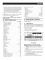
3.3 PRODUCTSPECIFICATIONS
3.3.1 GENERATORSPECIFICATIONS
RatedPower............................................................... 5.5/6.5/7.5 kW**
SurgePower....................................................... 6.875/8.125/9.375 kW
RatedACVoltage...................................................................... 120/240
RatedAC Load
Current@ 240V (5.5/6.5/7.5 kW)..................22.9/27.1/31.3 Amps**
Current@ 120V (5.5/6.5/7.5 kW)..................45.8/54.2/62.5 Amps**
RatedFrequency.................................................... 60 Hz@ 3600 RPM
Phase................................................................................ SinglePhase
** OperatingTemperatureRange: -18deg.C(0deg.F)to40Deg.C(104Deg.
F).Whenoperatedabove25deg.C(77deg.F)theremaybea decreasein
power.
** Maximumwattageandcurrentaresubjectto,andlimitedby,suchfactors
asfuelBtucontent,ambienttemperature,altitude,enginecondition,etc..
Maximumpowerdecreasesabout3.5%foreach1,000feetabovesealevel;
andwillalsodecreaseabout1%for each6° C(10° F)above16° C(60° F)
ambienttemperature.
3.3.2 ENGINESPECIFICATIONS
5.5/6.5kW
Displacement.............................................................................. 389 cc
SparkPlugType................................ NHSPLDF7TCor ChampionN9YC
SparkPlug PartNo........................................................... 0G84420101
SparkPlug Gap.............................0.028-0.031 inch or (0.70-0.80 mm)
GasolineCapacity..........................................25.6 L (6.77 U.S.gallons)
OilType.................. SeeChartin "Before Startingthe Generator"Section
OilCapacity................................................................. 1.0 L (1.06 Qts.)
RunTimeat 50% Load.............................................................10 Hours
12

7.5kW
Displacement............................................................................... 420cc
SparkPlugType................................ OhampionN9YOor NHSPLDF7TO
SparkPlug PartNo........................................................... 0G84420101
SparkPlug Gap.............................0.028-0.031 inch or (0.70-0.80 ram)
GasolineOapacity............................................28.4 L (7.5 U.S.gallons)
OilType.................. SeeOhartin "BeforeStartingthe Generator"Section
OilOapacity.......................................................... 1.0 Liters (1.06 Qts.)
RunTime (50%Load)..............................................................12 Hours
3.4 GENERALRECOMMENDATIONS
Thewarrantyof thegeneratordoes notcover itemsthat havebeen
subjectedto operator abuseor negligence.To receivefull value
from the warranty, the operator must maintain the generatoras
instructed inthis manual.
Some adjustmentswilt need to be made periodically to properly
maintainthegenerator.
All adjustmentsin the Maintenancesectionof this manualshould
be madeat leastonceeachseason.Followthe requirementsinthe
"MaintenanceSchedule".
NOTE:
Once a year replacethe spark plug and replacethe air filter.
A new spark plug and clean air filter assure properfuel-air
mixtureand helpthe engine runbetter and lastlonger.
3.4.1 GENERATORMAINTENANCE
Generatormaintenanceconsistsof keepingthe unitcleanand dry.
Operateand storethe unit in a cleandry environmentwhereit will
not be exposedto excessivedust,dirt, moistureor any corrosive
vapors.Coolingair slotsin thegeneratormustnot becomeclogged
with snow, leaves,or anyotherforeign material.
Checkthe cleanlinessof the generatorfrequentlyand cleanwhen
dust, dirt, oil, moistureor otherforeign substancesarevisible on
its exteriorsurface.
,&,CAUTION!
,_ Never insert any object or tool through the air
cooling slots, even if the engine is not running.
NOTE:
DONOTusea gardenhoseto cleangenerator. Water canenter
theenginefuel systemand causeproblems,in addition, ifwater
enters thegenerator throughcoolingair slots,somewaterwill
be retainedin voidsand crevicesof therotorand stator winding
insulation.Water and dirt buildup on the generator internal
windingswill eventually decreasetheinsulationresistanceof
thesewindings.
3.=/.2 TOCLEANTHEGENERATOR
* Usea dampcloth to wipe exteriorsurfaces clean.
. A soft, bristle brush may be usedto loosencaked on dirt, oil,
etc.
. A vacuumcleanermay be usedto pick up loosedirt anddebris.
. Low pressure air (not to exceed 25 psi) may be used to
blow away dirt. Inspect cooling air slots and openingson the
generator.Theseopeningsmustbekeptcleanandunobstructed.
3.4.3 ENGINEMAINTENANCE
When working on the generator, always
disconnect spark plug wire from spark plug and
keep wire away from spark plug.
3.4.4 CHECKINGOILLEVEL
Seethe "BeforeStartingtheGenerator"sectionfor informationon
checkingthe oil level.The oil levelshouldbe checkedbeforeeach
use, or at least every eight hours of operation. Keepthe oil level
maintained.
3.4.5 CHANGINGTHEOIL
Changethe oil after every 100 hours. If running this unit under
dirty or dusty conditions, or in extremelyhot weather,changethe
oil moreoften.
,A CAUTION!
,_Hot oil may cause burns. Allow engine to
cool before draining oil. Avoid prolonged
or repeated skin exposure with used oil.
Thoroughly wash exposed areas with soap.
Use thefollowing instructionsto changetheoil after the engine
coolsdown:
1. Cleanareaaroundoil drainplug.
2. Removeoil drain plugfrom engineand oil fill plug to drainoil
completelyinto a suitablecontainer.
3. When oil has completely drained, install oil drain plug and
tightensecurely.
4. Fill engine with recommendedoil. (See "Before Startingthe
Generator"for oil recommendations).
5. Wipeup anyspilledoil.
6. Disposeof usedoil at a propercollectioncenter.
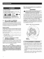
3.4.6 REPLACINGTHESPARKPLUG
Use ChampionN9YCspark plug or equivalent.Replacetheplug
every 200 hours.This will help the engine start easier and run
better.
1. Stopthe engineand pull the spark plug wire off of the spark
plug.
2. Cleanthe area aroundthe spark plug and remove it from the
cylinder head.
3. Setthe spark plug'sgap to 0.70-0.80 mm (0.028-0.031 in.).
Installthe correctly gappedspark plug intothe cylinder head
(Figure14).
Figure 14 - Spark Plug Gap
13

3.4.7 BATTERYREPLACEMENT(IFAPPL/CABLE_
NOTE:
Thebattery shippedwith thegenerator hasbeenfully charged.
A battery may lose some of its chargewhen not in use for
prolongedperiodsof time. if the battery is unable to crank
the engine,plug in the 12V chargerincludedin the accessory
box (see the Charging a Battery section). RUNNING THE
GENERATORDOESNOTCHARGETHEBATTERY.Thepartnumber
forthis battery is 0Gg44g.
,A CAUTION!
,_The NEGATWE battery terminal should:
1. Always beDISCONNECTEDFIRST.
2. Alwaysbe CONNECTEDLAST.
Figure15- Battery Connections
RED(+)
BLACK(-)
3.5 SERVICEAIRFILTER
Theenginewill not run properlyand may be damagedif usinga
dirty air filter. Cleanthe air filter every 50 hours or once a year
(Figure16). Cleanor replacemore often if operatingunderdusty
conditions.Theair filter part numberis 0G84420151.
1. Removeairfilter cover.
2. Washinsoapywater.Squeezefilter dry incleancloth (DONOT
TWIST).
3. Cleanair filter cover beforere-installingit.
NOTE:
Toordera new air filter, pleasecontactthe nearestauthorized
service centerat 1-888-436-3722.
Figure 16- Air Filter
KNOBTOOPENAIR BOX
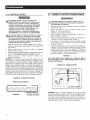
351 CLEANSPARKARRESTORSCREEN(CARB
MOOELS
The engineexhaustmuffler has a spark arrestor screen. Inspect
and cleanthe screenat least onceeachyear(Figure17). If unit is
usedregularly,inspectand cleanmoreoften.
//_lf using the generator on any forest=covered,
brush=covered or grass=covered unimproved
land, it must equipped with a spark arrestor.
The spark arrestor must be maintained in good
condition by the owner/operator.
Cleanandinspectthe sparkarrestorwhentheengineisat ambient
temperatureasfollows:
1. Remove the spark arrestor screen from the muffler by
looseningthe clamp andremovingthe screw.
2. Inspect screen and replace if torn, perforated or otherwise
damaged. DONOT USEa defective screen. If screen is not
damaged,cleanit with commercialsolvent.
3. Replacethe spark arrestor and secure with the clamp and
screw.
Figure 17 - Spark Arrestor Screen
14
Spark _'i
Arrestor_ i
Cone i_ Spark
..../Arrestor
_ Screen
C,amp

NOTE:
Toordera newair filteror sparkarrestorscreen,pleasecontact
thenearestauthorizedservicecenterat 1-800-333-1322,
3.6 VALVECLEARANCE
• Intake-- 0.15 _ 0.02mm (cold), (0.006" _ 0.0008" inches)
• Exhaust-- 0.20 _ 0.02mm (cold) (0.008" _ 0.0008" inches)
After the first 50 hours of operation, checkthe valve clearance
in the engine and adjustif necessary.
Important: If feelinguncomfortableaboutdoing this procedureor
theproper tools are not available,pleasetake the generatorto the
nearestservicecenterto havethevalveclearanceadjusted.This is
a very importantstepto ensurelongestlifefor theengine.
3.7 GENERAL
Thegeneratorshould be started at least once every 30 days and
be allowedto run at least 30 minutes. If this cannot be done and
the unit must be stored for morethan 30 days, use thefollowing
informationas a guideto prepareitfor storage.
NEVER store engine with fuel in tank indoors
or in enclosed, poorly ventilated areas where
fumes may reach an open flame, spark or pilot
light as on a furnace, water heater, clothes dryer
or other gas appliance.
,_Ailow unit to cool entirely before storage.
3.B LONGTERMSTORAGE
It is importantto preventgum depositsfrom forming in essential
fuel systemparts such asthe carburetor,fuel hoseor tank during
storage. Also, experience indicates that alcohol-blended fuels
(called gasohol,ethanolor methanol)can attract moisture,which
leadsto separationandformation of acids during storage.Acidic
gascan damagethefuel systemof an enginewhile in storage.
To avoid engine problems, the fuel system should be emptied
beforestorageof 30 daysor longer,asfollows:
1. Addaqualitygasolinestabilizertothefuelperthemanufacturer's
specifications,and run the unitfor 10-15 minutes.
2. After engine cools down, remove all gasolinefrom the fuel
tank. Use a commerciallyavailable, non-conductivevacuum
siphon.
Drain fuel into approved container outdoors,
away from open flame. Be sure engine is cool.
Do not smoke.
3. Start and run engineuntilenginestopsfrom lackof fuel.
4. After engine cools down, drain oil from engine. Refill with
recommendedgrade.
5. Remove spark plug and pour about 1/2 ounce (15 mt) of
engineoil intothecylinder.Coverspark plugholewith rag.Pull
the recoil starter a coupletimes to lubricatethe piston rings
and cylinder bore.A fogging agent can also be used in the
placeof oil.
ACAUTION!
,_Avoid spray from spark plug hole when
cranking engine.
6. Installandtightenspark plug.Donot connectsparkplugwire.
7. Cleanthe generatorouter surfaces. Check that cooling air
slots andopeningson generatorareopenand unobstructed.
8. Storethe unit in a clean, dry place.
3.9 OTHERSTORAGETiPS
• Do notstoregasolinefrom oneseasonto another.
• Replacethe gasolinecan if it starts to rust. Rustand/ordirt in
the gasolinewill cause problems with the carburetor and fuel
system.
• If possible,storethe unit indoorsandcoverit to giveprotection
from dust anddirt. BESURETOEMPTYTIdEFUELTANK.
• If it is not practicalto empty the fuel tank and the unit is to
be stored for some time, use a commercially availablefuel
stabilizer added to the gasoline to increase the life of the
gasoline.Runthe unitfor 10-15 minutes,turn off thefuelvalve
and allowto run untilenginestopsfrom lack of fuel.
• Coverthe unit with a suitable protective cover that does not
retainmoisture.
,_ NEVER cover the generator while engine and
exhaust areas are warm.
15

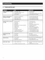
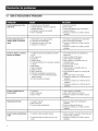
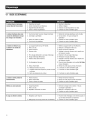
4.1TBOUBLESHOOTINGGUIDE
Engineis running,but no AC output
isavailable.
1. Circuitbreakeris open.
2. Poorconnectionor defectivecord set.
3. Connecteddeviceis bad.
4. Faultin generator.
1. Resetcircuit breaker.
2. Checkand repair.
3. Connectanotherdevicethat is in goodcondition.
4. ContactAuthorizedServiceFacility.
Engineruns well hut bogs down 1. Short circuit in a connectedload. 1. Disconnectshorted electricalload.
whenloadsare connected. 2. Generatoris overloaded. 2. See"Don't Overloadthe Generator".
3. Enginespeedis too slow. 3. ContactAuthorizedServiceFacility.
4. Shorted generatorcircuit. 4. ContactAuthorizedServiceFacility.
I I
Enginewill notstart;orstartsand
runsrough.
1. FuelShut-off is OFF.
2. Dirty airfilter.
3. Outof gasoline.
4. Stalegasoline.
5. Sparkplug wire not connectedto sparkplug.
1. TurnFuelShut-off ON.
2. Cleanor replaceairfilter.
3. Fillfuel tank.
4. Drainfuel tank andfill with fresh fuel.
5. Connectwire to sparkplug.
6. Badsparkplug.
7. Waterin gasoline.
8. Overchoking.
9. Low oil level.
10. Excessiverichfuel mixture.
11. Intakevalvestuck openor closed.
12. Enginehas lostcompression.
6. Replacespark plug.
7. Drainfuel tank;fill with fresh fuel.
8. Putchokeknobto No Chokeposition.
9. Fillcrankcaseto properlevel.
10. ContactAuthorizedServiceFacility.
11. ContactAuthorizedServiceFacility.
12. ContactAuthorizedServiceFacility.
= I
Engineshuts downduring 1. Outof gasoline. 1. Fillfuel tank.
operation. 2. Low oil level. 2. Fillcrankcaseto properlevel.
3. Faultin engine. 3. ContactAuthorizedServiceFacility.
m R
Enginelacks power. 1. Loadis too high. 1. Reduceload(see"Don't Overloadthe Generator").
2. Dirty airfilter. 2. Cleanor replaceairfilter.
3. Engineneedsto be serviced. 3. ContactAuthorizedServiceFacility.
= I
Engine"hunts" or falters. 1. Chokeis openedtoo soon. 1. Movechoketo halfway positionuntil engineruns
smoothly.
2. Carburetoris runningtoo rich or too lean. 2. ContactAuthorizedServiceFacility.
16
Page is loading ...

Manual PartNo.0K0172 Rev.D (01/31/13) Printedin China
Page is loading ...
Page is loading ...
Page is loading ...
Page is loading ...
Page is loading ...
Page is loading ...
Page is loading ...
Page is loading ...
Page is loading ...
Page is loading ...
Page is loading ...
Page is loading ...
Page is loading ...
Page is loading ...
Page is loading ...
Page is loading ...
Page is loading ...
Page is loading ...
Page is loading ...
Page is loading ...
Page is loading ...
Page is loading ...
Page is loading ...
Page is loading ...
Page is loading ...
Page is loading ...
Page is loading ...
Page is loading ...
Page is loading ...
Page is loading ...
Page is loading ...
Page is loading ...
Page is loading ...
Page is loading ...
Page is loading ...
Page is loading ...
Page is loading ...
Page is loading ...
Page is loading ...
Page is loading ...
-
 1
1
-
 2
2
-
 3
3
-
 4
4
-
 5
5
-
 6
6
-
 7
7
-
 8
8
-
 9
9
-
 10
10
-
 11
11
-
 12
12
-
 13
13
-
 14
14
-
 15
15
-
 16
16
-
 17
17
-
 18
18
-
 19
19
-
 20
20
-
 21
21
-
 22
22
-
 23
23
-
 24
24
-
 25
25
-
 26
26
-
 27
27
-
 28
28
-
 29
29
-
 30
30
-
 31
31
-
 32
32
-
 33
33
-
 34
34
-
 35
35
-
 36
36
-
 37
37
-
 38
38
-
 39
39
-
 40
40
-
 41
41
-
 42
42
-
 43
43
-
 44
44
-
 45
45
-
 46
46
-
 47
47
-
 48
48
-
 49
49
-
 50
50
-
 51
51
-
 52
52
-
 53
53
-
 54
54
-
 55
55
-
 56
56
-
 57
57
-
 58
58
-
 59
59
-
 60
60


Generac 5943-5 Owner's manual
- Category
- Power generators
- Type
- Owner's manual
- This manual is also suitable for
Ask a question and I''ll find the answer in the document
Finding information in a document is now easier with AI
in other languages
- français: Generac 5943-5 Le manuel du propriétaire
- español: Generac 5943-5 El manual del propietario
Related papers
Other documents
-
Craftsman 580.327750 Owner's manual
-
Sears Portable Generator 005735-0 User manual
-
Franklin Chef FBC20 Owner's manual
-
Franklin Chef FBC36OD Owner's manual
-
 AC Tool Supply XG8000 Owner's manual
-
Alto 005802-2 Owner's manual
-
Amana AP095R User manual
-
Firman H05752 Reference guide
-
 Aircommand IBIS ROOFTOP CARAVAN Owner's manual
-
Carrier ASPB07-1SI User manual

