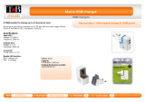
PC CHIPS M935DLU (V2.0) User manual
- Category
- Motherboards
- Type
- User manual

This publication, including all photographs, illustrations and
software, is protected under international copyright laws, with all
rights reserved. Neither this manual, nor any of the material
contained herein, may be reproduced without the express written
consent of the manufacturer.
The information in this document is subject to change without
notice. The manufacturer makes no representations or warranties
with respect to the contents hereof and specifically disclaims any
implied warranties of merchantability or fitness for any particular
purpose. Further, the manufacturer reserves the right to revise this
publication and to make changes from time to time in the content
hereof without obligation of the manufacturer to notify any person
of such revision or changes.
Trademarks
IBM, VGA, and PS/2 are registered trademarks of International
Business Machines.
Intel, Pentium/II/III, Pentium 4, Celeron and MMX are registered
trademarks of Intel Corporation.
Microsoft, MS-DOS and Windows 98/ME/NT/2000/XP are
registered trademarks of Microsoft Corporation.
PC-cillin is a registered trademark of Trend Micro Inc.
AMI is a registered trademark of American Megatrends Inc.
SiS is a trademark of Silicon Integrated System Corporation.
Other names used in this publication may be trademarks and are
acknowledged.
Copyright © 2003
All Rights Reserved
M935D Series, V2.0A
S650GX/September 2003

Table of Contents
Trademark .....................................................................................I
Static Electricity Precautions.................................................III
Pre-Installation Inspection.....................................................III
Features & Checklist Translations..............................................V
Chapter 1: Introduction................................................................1
Key Features............................................................................2
Package Contents.....................................................................5
Chapter 2: Mainboard Installation..............................................6
Mainboard Components ..........................................................7
I/O Ports...................................................................................8
Installing the Processor............................................................9
Installing Memory Modules ..................................................10
Jumper Settings......................................................................11
Install the Mainboard.............................................................12
Connecting Optional Devices................................................13
Install Other Devices .............................................................16
Expansion Slots ....................................................................18
Chapter 3: BIOS Setup Utility ...................................................19
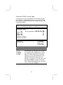
Introduction ...........................................................................19
Running the Setup Utility...........…………………………...20
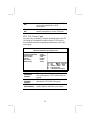
Standard CMOS Setup Page..................................................21
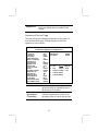
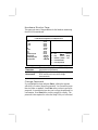
Advanced Setup Page............................................................22
Power Management Setup Page ............................................25
PCI/Plug and Play Setup Page...............................................27
Load Optimal Settings...........................................................28
Load Best Performance Settings............................................28
Features Setup Page...............................................................28
CPU PnP Setup Page.............................................................30
Hardware Monitor Page.........................................................31
Change Password...................................................................31
Exit ........................................................................................32
Chapter 4: Software & Applications..........................................33
Introduction ...........................................................................33
Installing Support Software...................................................34
Bundled Software Installation...............................................36
II

Static Electricity Precautions
Components on this mainboard can be damaged by static
electricity. Take the following precautions when unpacking the
mainboard and installing it in a system.
1. Keep the mainboard and other components in their original
static-proof packaging until you are ready to install them.
2. During installation, wear a grounded wrist strap if possible. If
you don’t have a wrist strap, discharge static electricity by
touching the bare metal of the system chassis.
3. Handle the mainboard carefully by the edges. Avoid touching
the components unless it is absolutely necessary. During
installation put the mainboard on top of the static-protection
packaging it came in with the component side facing up.
Pre-Installation Inspection
1. Inspect the mainboard for damage to the components and
connectors on the board.
2. If you suspect that the mainboard has been damaged, do not
connect power to the system. Contact your mainboard vendor
and report the damage.
III

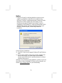
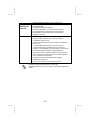
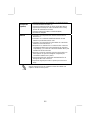
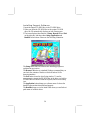
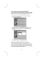
Notice:
1. Owing to Microsoft’s certifying schedule is various to every
supplier, we might have some drivers not certified yet by
Microsoft. Therefore, it might happen under Windows XP that a
dialogue box (shown as below) pop out warning you this
software has not passed Windows Logo testing to verify its
compatibility with Windows XP. Please rest assured that our RD
department has already tested and verified these drivers. Just
click the “Continue Anyway” button and go ahead the
installation.
2.USB 2.0 Driver Limitations:
2-1. The USB 2.0 driver only supports Windows XP and Windows
2000.
2-2. If you connect a USB 2.0 hub to the root hub, plugging USB
devices into this hub, the system might not successfully
execute certain USB devices’ connection because it could not
recognize these devices.
Currently, we are working on such limitations’ solution. As soon as
the solution is done, the updated USB drive will be released to our
website: www.pcchips.com.tw
for your downloading.
IV
Page is loading ...
Page is loading ...
Page is loading ...
Page is loading ...
Page is loading ...

• Supporto delle impostazioni per la negoziazione automatica
IEEE 802.3u
• Supporto delle operazioni nella modalità Link Down Power
Saving
• Supporto della compensazione Base Line Winder (BLW)
• Equalizzazione adattabile
USB 2.0
• Compliant with Universal Serial Bus Specification Revision 2.0
• Compliant with Intel’s Enhanced Host Controller Interface
Specification Revision 0.95
• Compliant with Universal Host Controller Interface Specification
Revision 1.1
• PCI multi-function device consists of two UHCI Host Controller
cores for full-/low-speed signaling and one EHCI Host
Controller core for high-speed signaling
• Root hub consists 4 downstream facing ports with integrated
physical layer transceivers shared by UHCI and EHCI Host
Controller
• Support PCI-Bus Power Management Interface Specification
release 1.1
• Legacy support for all downstream facing ports
Alcune specifiche hardware ed elementi software sono soggetti a
variazioni senza preavviso.
X
Page is loading ...
Page is loading ...
Page is loading ...
Page is loading ...
Page is loading ...
Page is loading ...

Chapter 1
Introduction
This mainboard has a Socket-478 processor socket for Intel
Pentium 4 processors with front-side bus (FSB) speeds up to
533 MHz.
This mainboard integrates the SiS650GX Northbridge along with
SiS962L Southbridge chipsets that supports built-in AC97 Codec ,
2 DDR modules up to 2GB system memory, and provides Ultra
DMA 33/66/100/133 function. These chipsets’ function is detailed
as the Chipset description in next section. This mainboard
integrates a 256-bit 3D/2D Graphics Engine, Video Accelerator
and Advanced Hardware Acceleration MPEGI/MPEGII Video
Decoder for the Intel Pentium 4 series based PC systems. It has the
external AGP slot with AGP 4X 266MHz capability, one CNR
(Communications and Networking Riser) slot, and built-in
10BaseT/100BaseTX Network Interface (optional). In addition,
there is a full set of I/O Ports including PS/2 keyboard and mouse
ports, one serial port, one VGA port, one parallel port, and
maximum six USB2.0 ports – four back-panel ports and onboard
USB header JUSB1 providing two extra ports by connecting the
Extended USB Module to the mainboard.
This mainboard is Micro ATX size and has power connectors for
an ATX power supply and measures 244 x 190mm.

Key Features
The key features of this mainboard include:
Socket-478 Processor
♦ The PGA Socket 478
♦ Supports Intel Pentium 4 series CPU
♦ Supports up to 533 MHz Front-Side Bus
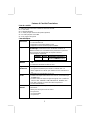
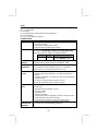
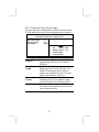
Chipset
There are SiS650GX Northbridge and SiS962L Southbridge in
this chipset in accordance with an innovative and scalable
architecture with proven reliability and performance. Here is a list
of the chipset arrangement and their respective features:
Northbridge Southbridge Function
SiS650GX SiS962L CPU FSB: 533MHz, Ultra DMA
ATA133, DDR333, USB2.0
Memory Support
♦ Two 184-pin DIMM sockets for DDR333 memory modules
♦ Maximum installed memory is 2GB
Expansion Slots
♦ One CNR slot
♦ One 2x/4xAGP slot for AGP 2.0-compliant interface
♦ Two 32-bit PCI slots for PCI 2.2-compliant bus interface
Onboard IDE channels
♦ Primary and Secondary PCI IDE channels
♦ Support for PIO (programmable input/output) modes
♦ Support for Multiword DMA modes
♦ Support for Bus Mastering and Ultra DMA ATA
33/66/100/133 modes
Power Supply and Power Management
♦ ATX power supply connector
♦ Meets ACPI 1.0b and APM 1.2 requirements, keyboard
power on/off
2

♦ Supports RTC Alarm, Wake On Modem, AC97 Wake-Up
and USB Wake-Up
Onboard VGA
♦ Supports AGP V2.0 Compliant
♦ Supports AGP 4X/2X interface and Fast Write Transaction
♦ Supports high performance & high quality 3D
Accelerator—A built-in 256-bit 3D engine, up to 143 MHz
3D engine clock speed
♦ Supports high performance 128-bit 2D Accelerator—Ultra-
AGPII
TM
2GB/s data read for all 2D engine functions
♦ Maximum Share Memory size is 64MB
AC97 Audio Codec
♦ Compliant with AC’97 2.2 specification
♦ 16—bit stereo full-duplex CODEC with fixed 48KHz
sampling rate
♦ 3 analog line-level stereo inputs with 5-bit volume control:
LINE-IN, CD-IN, AUX-IN
♦ 2Ch DAC, support 2-channel speak-out
♦ Power management
Built-in Ethernet LAN (optional)
♦ Supports 10/100Mbps operation and half/full duplex
operation
♦ IEEE 802.3/802.3u compliant
♦ Supports IEEE 802.3u clause 28 auto negotiation
♦ Supports operation under Link Down Power Saving mode
♦ Supports Base Line Winder (BLW) compensation
♦ Adaptive Equalization
Onboard I/O Ports
The mainboard has a full set of I/O ports and connectors:
♦ Two PS/2 ports for mouse and keyboard
♦ One serial port
♦ One parallel port
♦ One VGA port
3

♦ Four back-panel USB2.0 ports and extra two USB2.0 ports
(onboard USB connector JUSB1)
♦ Audio jacks for microphone, line-in and line-out
Hardware Monitoring
♦ Built-in hardware monitoring for CPU & System
temperatures, fan speeds and mainboard voltages.
Onboard Flash ROM
♦ Supports Plug and Play configuration of peripheral devices
and expansion cards
USB 2.0
♦ Compliant with Universal Serial Bus Specification
Revision 2.0
♦ Compliant with Intel’s Enhanced Host Controller
Interface Specification Revision 0.95
♦ Compliant with Universal Host Controller Interface
Specification Revision 1.1
♦ PCI multi-function device consists of two UHCI Host
Controller cores for full-/low-speed signaling and one
EHCI Host Controller core for high-speed signaling
♦ Root hub consists 4 downstream facing ports with
integrated physical layer transceivers shared by UHCI and
EHCI Host Controller
♦ Support PCI-Bus Power Management Interface
Specification release 1.1
♦ Legacy support for all downstream facing ports
Bundled Software
♦ PC-Cillin2002 provides automatic virus protection under
Windows 98/ME/NT/2000/XP
♦ Adobe Acrobat Reader V5.0 is the software to help users
read .PDF files.
Dimensions
♦ Micro ATX form factor 244 x 190mm
4

Package Contents
Your mainboard package contains the following items:
The mainboard
The User’s Manual
One diskette drive ribbon cable (optional)
One IDE drive ribbon cable
Software support CD
Optional Accessories
You can purchase the following optional accessories for this
mainboard.
Extended USB module
CNR v.90 56K Fax/Modem card
Card Reader
Note: You can purchase your own optional accessories from the
third party, but please contact your local vendor on any
issues of the specification and compatibility.
5

Chapter 2
Mainboard Installation
To install this mainboard in a system, please follow the instructions
in this chapter:
Identify the mainboard components
Install a CPU
Install one or more system memory modules
Verify that all jumpers or switches are set correctly
Install the mainboard in a system chassis (case)
Connect any extension brackets or cables to connectors on the
mainboard
Install any peripheral devices and make the appropriate
connections to connectors on the mainboard
Note:
1. Before installing this mainboard, make sure jumper JP2 is
under Normal setting. See this chapter for information about
locating JP2 and the setting options.
2. Never connect power to the system during installation;
otherwise, it may damage the mainboard.

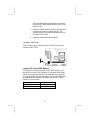
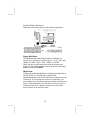
Mainboard Components
Use the diagram below to identify the major components on the
mainboard.
Note: Any jumpers on your mainboard not appearing in the
illustration above are for testing only.
7

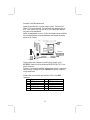
I/O Ports
The illustration below shows a side view of the built-in I/O ports
on the mainboard.
(
o
p
tional
)
(shared
with
READ1
)
PS/2 Mouse
Use the upper PS/2 port to connect a PS/2
pointing device.
PS/2 Keyboard
Use the lower PS/2 port to connect a PS/2
keyboard.
LPT1
Use LPT1 to connect printers or other
parallel communications devices.
COM1
Use the COM port to connect serial devices
such as mice or fax/modems. COM1 is
identified by the system as COM1.
VGA
Use the VGA port to connect VGA devices.
LAN Port
(optional)
Connect an RJ-45 jack to the LAN port to
connect your computer to the Network.
USB Ports
Use the USB ports to connect USB devices.
Note: The lower USB port located beside the
VGA port is shared with the READ1 connector.
Audio Ports
Use the three audio ports to connect audio
devices. The first jack is for stereo Line-In
signal. The second jack is for stereo Line-
Out signal. The third jack is for
Microphone.
8

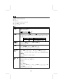
Installing the Processor
This mainboard has a Socket 478 processor socket. When choosing
a processor, consider the performance requirements of the system.
Performance is based on the processor design, the clock speed and
system bus frequency of the processor, and the quantity of internal
cache memory and external cache memory.
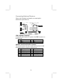
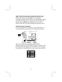
CPU Installation Procedure
Follow these instructions to install the CPU:
Pin 1
Socket
-
478
CPUFAN
1
1. Unhook the locking lever of the CPU socket. Pull
the locking lever away from the socket and raising
it to the upright position.
2. Match the pin1 corner (the beveled edge) on the
CPU with the pin1 corner on the socket (shown as
the above illustration). Insert the CPU into the
socket. Do not use force.
3. Push the locking lever down and hook it under the
latch on the edge of socket.
4. Apply thermal grease to the top of the CPU.
5. Install the cooling fan/heatsink unit onto the CPU,
and secure them all onto the socket base.
6. Plug the CPU fan power cable into the CPU fan
connector (CPUFAN) on the mainboard.
9

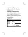
Installing Memory Modules
This mainboard accommodates two 184-pin 2.5V unbuffered
Double Data Rate SDRAM (DDR SDRAM) Dual Inline Memory
Module (DIMM) sockets, and supports up to 2.0 GB of 333 MHz
DDR SDRAM.
DDR SDRAM is a type of SDRAM that supports data transfers on
both edges of each clock cycle (the rising and falling edges),
effectively doubling the memory chip’s data throughput. DDR
DIMMs can synchronously work with 100 MHz or 133 MHz
memory bus.
DDR SDRAM provides 1.6 GB/s or 2.1 GB/s data transfer rate
depending on whether the bus is 100 MHz or 133 MHz.
DDR SDRAM uses additional power and ground lines and requires
184-pin 2.5V unbuffered DIMM module.
DIMM1
DIMM2
Installation Procedure
These modules can be installed with up to 2 GB system memory.
Following these steps to install the memory module.
1. Push down the latches on both sides of the DIMM
socket.
2. Align the memory module with the socket. There is
a notch on the DIMM socket that you can install the
10

DIMM module in the correct direction. Match the
cutout on the DIMM module with the notch on the
DIMM socket.
3. Install the DIMM module into the socket and press
it firmly down until it is seated correctly. The
socket latches are levered upwards and latch on to
the edges of the DIMM.
4. Install any remaining DIMM modules.
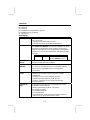
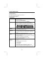
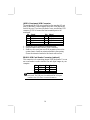
Jumper Settings
Using a jumper cap to connect two pins is SHORT, removing it
from these pins, OPEN.
1
JP2
Jumper JP2: Clear CMOS Memory
This jumper can clear the contents of the CMOS memory. You
may need to clear the CMOS memory if the settings in the Setup
Utility are incorrect and prevent your mainboard from operating.
To clear the CMOS memory, disconnect all the power cables from
the mainboard and then move the jumper cap into the CLEAR
setting for a few seconds.
Function Jumper Setting
Clear CMOS Short Pins 1-2
Normal Mode Short Pins 2-3
11

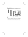
Install the Mainboard
Install the mainboard in a system chassis (case). The board is a
Micro ATX size mainboard. You can install this mainboard in an
ATX case. Ensure your case has an I/O cover plate that matches
the ports on this mainboard.
Install the mainboard in a case. Follow the instructions provided by
the case manufacturer using the hardware and internal mounting
points on the chassis.
ATX2
1
SW1
CHSFA
N
1
A
TXPW1
Connect the power connector from the power supply to the
ATXPW1 connector on the mainboard. ATX2 is the CPU Vcore
power connector.
If there is a cooling fan installed in the system chassis, connect the
cable from the cooling fan to the CHSFAN fan power connector
on the mainboard.
Connect the case switches and indicator LEDs to the SW1
connector.
Pin Signal Pin Signal
1 HDD_LED_P 2 FP ACPI LED
3 HDD_LED_N 4 FP ACPI LED
5 RST_SW_N 6 PW_BT_P
7 RST_SW_P 8 PW_BT_N
9 RSVD_DNU 10 KEY
12

Connecting Optional Devices
Refer to the following for information on connecting the
mainboard’s optional devices:
1
1
READ1
A
UDIO2
JUSB1
1
1
1
SPK1
IR1
SPK1: Speaker Connector
Connect the cable from the PC speaker to the SPK1 connector on
the mainboard.
Pin Signal Pin Signal
1 SPKR 2 NC
3 GND 4 +5V
AUDIO2: Front Panel Audio Connector
This connector allows the user to install auxiliary front-oriented
microphone and line-out ports for easier access.
Pin Signal Pin Signal
1 AUD_MIC 2 AUD_GND
3 AUD_MIC 4 AUD_VCC
5 AUD_FPOUT 6 AUD_RET_R
7 NC 8 KEY
9 AUD_FPOUT 10 AUD_RET_L
13

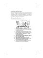
JUSB1: Front panel USB Connector
The mainboard has USB ports installed on the rear edge I/O port
array. Additionally, some computer cases have USB ports at the
front of the case. If you have this kind of case, use auxiliary USB
connector JUSB1 to connect the front-mounted ports to the
mainboard.
Pin Signal Pin Signal
1 VCC 2 VCC
3 DATA1- 4 DATA2-
5 DATA1+ 6 DATA2+
7 GND 8 GND
9 KEY 10 NC
1. Locate the JUSB1 connector on the mainboard.
2. Plug the bracket cable onto the JUSB1 connector.
3. Remove a slot cover from one of the expansion slots on the
system chassis. Install an extension bracket in the opening.
Secure the extension bracket to the chassis with a screw.
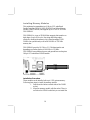
READ1: USB Card Reader Connector (optional)
This connector is for connecting internal USB card reader. You can
use a card reader to read or transfer files and digital images to your
computer.
Pin Signal Pin Signal
1 VCC 2 USB-
3 USB+ 4 GND
5 KEY
The READ1 is shared with one of the USB ports of the I/O
back panel. The USB port is located beside the VGA port
connector. See “I/O Ports” for more information.
14

Please check the pin assignment of the cable and the USB
header on the mainboard. Make sure the pin assignment
will match before plugging in. Any incorrect usage may
cause unexpected damage to the system. The vendor won’t
be responsible for any incidental or consequential damage
arising from the usage or misusage of the purchased
product.
IR1: Infrared Port
The infrared port allows the wireless exchange of information
between your computer and similarly equipped devices such as
printers, laptops, Personal Digital Assistants (PDAs), and other
computers.
Pin Signal Pin Signal
1 NC 2 KEY
3 +5V 4 GND
5 IRTX 6 IRRX
1. Locate the infrared port IR1 connector on the mainboard.
2. If you are adding an infrared port, connect the ribbon cable
from the port to the IR1 connector and then secure the port to
an appropriate place in your system chassis.
15
Page is loading ...
Page is loading ...
Page is loading ...
Page is loading ...
Page is loading ...
Page is loading ...
Page is loading ...
Page is loading ...
Page is loading ...
Page is loading ...
Page is loading ...
Page is loading ...
Page is loading ...
Page is loading ...
Page is loading ...
Page is loading ...
Page is loading ...
Page is loading ...
Page is loading ...
Page is loading ...
Page is loading ...
-
 1
1
-
 2
2
-
 3
3
-
 4
4
-
 5
5
-
 6
6
-
 7
7
-
 8
8
-
 9
9
-
 10
10
-
 11
11
-
 12
12
-
 13
13
-
 14
14
-
 15
15
-
 16
16
-
 17
17
-
 18
18
-
 19
19
-
 20
20
-
 21
21
-
 22
22
-
 23
23
-
 24
24
-
 25
25
-
 26
26
-
 27
27
-
 28
28
-
 29
29
-
 30
30
-
 31
31
-
 32
32
-
 33
33
-
 34
34
-
 35
35
-
 36
36
-
 37
37
-
 38
38
-
 39
39
-
 40
40
-
 41
41
-
 42
42
-
 43
43
-
 44
44
-
 45
45
-
 46
46
-
 47
47
-
 48
48
-
 49
49
-
 50
50
-
 51
51
-
 52
52


PC CHIPS M935DLU (V2.0) User manual
- Category
- Motherboards
- Type
- User manual
Ask a question and I''ll find the answer in the document
Finding information in a document is now easier with AI
Related papers
-
PC CHIPS M810DG (V8.0a) User manual
-
-
-
-
-
ECS T12 (V1.0a) User manual
-
-
-
ECS M985G Series User manual
-