ENGLISH
GENERAL SPECIFICATIONS
The RT250 is an electrical circuit tester that tests the wiring conditions at an
electrical outlet, and inspects GFCI devices. The LCD displays the voltage, the
wiring fault, and the GFCI trip time. It is designed for use with North American
120V electrical outlets.
• Operating Altitude: 6562 ft. (2000m)
• Relative Humidity: <85% non-condensing
• Operating Temp: 32° to 122°F (0° to 50°C)
• Storage Temp: -4° to 140°F (-20° to 60°C)
• Dimensions: 4.5" x 2.0" x 1.3" (114 x 50 x 33 mm)
• Weight: 4.8 oz. (136 g) including batteries
• Battery Type: 2 x 1.5V AAA Alkaline
• Standards: Conforms to UL STD.61010-1,
61010-2-030, 1436
Certified to CSA STD C22.2 # 61010-1,
61010-2-030, 160
• Pollution degree: 2
• Drop Protection: 6.6 ft. (2m)
• Safety Rating: CAT II 135V
CAT II: Measurement Category II is applicable to test and measuring circuits
connected directly to utilization points (socket outlets and similar points) of the
low-voltage MAINS installation.
Specifications subject to change.
WARNINGS
To ensure safe operation and service of the tester, follow these instructions.
Failure to observe these warnings can result in severe injury or death.
• RT250 is designed for use with North American 120V electrical
outlets
. DO
NOT connect to higher voltage electrical supplies.
• Prior to use, always verify tester operation by testing on a known live and
correctly wired electrical
circuit
.
• DO NOT use if the tester appears damaged in any way.
• The tester is intended for indoor use only.
• Other equipment or devices attached to the circuit being tested could interfere
with the tester. Clear the circuit before testing.
• This tester only detects common wiring problems. Always consult a qualified
electrician to resolve wiring problems.
• DO NOT attempt GFCI ground fault testing on an incorrectly wired
circuit
. Consult
a qualified electrician to resolve wiring problems.
•
For use on 3-wire outlets only.
OPERATING INSTRUCTIONS
GFCI GROUND FAULT TESTING
NOTE: Prior to using this tester, check the GFCI device’s user manual for
information on how the specic device operates.
Power ON the tester
1
and insert the plug into the outlet of the circuit under test.
On a properly wired circuit, the green Indicator LED
4
, the Hazardous Voltage
Indicator
F
and the Correct Wiring Indicator
G
will illuminate.
If the tester indicates that the circuit is not wired correctly, DO NOT attempt
to initiate an electrical testing event. Consult a qualied electrician.
To initiate an electrical fault, press the GFCI button. The tester will create a 6mA
to 9mA ground fault to trip the GFCI device. If successful, the display will toggle
A
between the pre-test voltage and time to trip the breaker. If the circuit remains
energized, or if "
>
sec" appears on the LCD, the device being tested may be
miswired, may not be installed correctly, or may not be functioning correctly.
Consult a qualied electrician.
BATTERY REPLACEMENT
When the Low Battery Indicator
E
illuminates, replace the batteries.
1. Loosen screw from battery cover
5
.
2. Replace 2 x AAA batteries (note proper polarity).
3. Replace battery door and fasten securely with screw.
To avoid risk of electric shock, unplug from any voltage source before removing
battery door.
To avoid risk of electric shock, do not operate tester while battery door is removed.
CLEANING
Be sure tester is turned off and wipe with a clean, dry lint-free cloth.
Do not
use abrasive cleaners or solvents.
STORAGE
Remove the batteries when tester is not in use for a prolonged period
of time. Do not expose to high temperatures or humidity. After a period
of storage in extreme conditions exceeding the limits mentioned in
the General Specifications section, allow the tester to return to normal
operating conditions before using.
WARRANTY
www.kleintools.com/warranty
DISPOSAL / RECYCLE
Do not place equipment and its accessories in the trash. Items must be
properly disposed of in accordance with local regulations. Please see
www.epa.gov or www.erecycle.org for additional information.
CUSTOMER SERVICE
KLEIN TOOLS, INC.
450 Bond Street Lincolnshire, IL 60069 1-800-553-4676
OPERATING INSTRUCTIONS
RT250 is designed for use with North American 120V electrical outlets. DO
NOT connect to higher voltage electrical supplies.
POWER ON/OFF
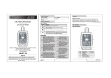
Press and hold the power button
1
for two seconds to power ON/OFF the tester.
When the tester is powered ON and not connected to a circuit, the LCD
3
will
display "
"
A
and "Open Hot"
B
condition.
NOTE: The tester will
automatically power OFF after 3 minutes of inactivity to conserve battery life.
WIRING CONDITION
Prior to use, always verify tester operation by testing on a known live and
correctly wired electrical outlet.
With the tester powered ON and inserted in the outlet, the Hazardous Voltage
Indicator
F
will appear, and the red or green Indicator LED(s)
4
will illuminate. If
the red indicator LED illuminates, unplug the tester to read voltage
A
and wiring
fault
B
. The tester holds the information on the LCD and the Hold Mode indicator
D
will illuminate. During this time the LCD will blink. The LCD will reset once it is
plugged into another circuit, or, if no voltage is detected, the LCD will blink during the
time-out period prior to auto-power off.
If the tester indicates that the circuit is not wired correctly, consult a
qualied electrician.
NOTE: Conditions NOT indicated include, but are not limited to, quality of ground,
multiple hot wires, reversal of neutral and ground conductors, and combinations of
defects other than dual open neutral and ground.
NOTE: All appliances or equipment on the circuit being tested should be unplugged to
help reduce the possibility of erroneous readings.
*Expected voltage reading on LCD based on the indicated wiring condition.
NOTE: If the detected voltage is either low (30–85V AC) or high (135–150V AC), the red
LED will illuminate. It is possible to have the red LED (indicating low or high voltage) and
the green LED (indicating correct wiring) illuminated simultaneously.
LCD WILL DISPLAY LED
VOLTAGE*
"CORRECT"
"OPEN GRD"
"OPEN NEU"
"OPEN HOT"
"HOT/GRD REV"
"HOT/NEU REV"
"OPEN GRD NEU"
GREEN
RED
LINE VOLTAGE
NO VOLTAGE
>30V VOLTAGE
WIRING CONDITION
WIRED CORRECTLY
OPEN GROUND
OPEN NEUTRAL
OPEN HOT
DUAL OPEN (NEUTRAL & GROUND)
REVERSED HOT/GROUND
REVERSED HOT/NEUTRAL
Hot
(Black)
Neutral
(White)
Ground (Green)
Indicator not illuminated
Indicator illuminated